Transcription
UAS-NASLive Virtual ConstructiveDistributed Environment(LVC)LVC Gateway, Gateway Toolbox,National Aeronautics andSpace AdministrationGateway Data Logger (GDL), SaaProcAmes Research CenterMoffett Field, CA 94035-1000Software Design DescriptionLVC SWDD-03Rev BRelease Date:April 20, 2015
LVC SWDD-03 Rev BRevision LogVersionDateApril 20, 2015Change ##PageAuthorDescription#Baseline May 1, 20130AllSrba JovicInitial Release of DocumentRev AFeb 19, 2014AllSrba JovicRevision to support the IHITLdevelopment phase.Rev BApr 20, 2015AllSrba JovicRevision to support the FT3development phase.iii P a g e
LVC SWDD-03 Rev BApril 20, 2015Table of Contents1.0 Introduction .11.1 Scope and Overview .42.0 Reference Documents .53.0 Software Design and Development Considerations .63.1 Programming languages .63.2 LVC Software .63.3 LVC Source Code Management .64.0 System Architecture Design .75.0 LVC Gateway Design .75.1 LVC Gateway Class Diagram .85.2 Data Flow .115.3 Sequence Diagram .156.0 LVC Gateway Data Logger Design .287.0 LVC Gateway Toolbox Design .297.1 LVC Gateway Toolbox Class Diagram .298.0 Sense and Avoid Processor (SaaProc) Design .308.1 SaaProc Class Diagram .319.0 Software Requirements Traceability and Implementation .35Appendix A – Acronyms .36iv P a g e
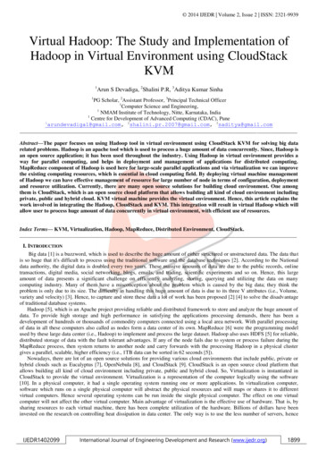
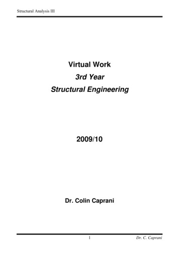
LVC SWDD-03 Rev BApril 20, 20151.0 IntroductionThe desire for a capability to fly government and commercial Unmanned Aircraft Systems(UAS) in the National Airspace System (NAS) is of increasing urgency. The application ofunmanned aircraft to perform national security, defense, scientific, and emergency managementfunctions are driving the critical need for less restrictive access by UAS to the NAS. UASrepresent a new capability that will provide a variety of services in the government (public) andcommercial (civil) aviation sectors. The growth of this potential industry has not yet beenrealized due to the lack of a common understanding of what is required to safely operate UAS inthe NAS.NASA’s UAS Integration into the NAS Project is conducting research in the areas of Sense andAvoid/Separation Assurance Interoperability (SAA), Human Systems Integration,Communication, and Certification to support reducing the barriers of UAS access to the NAS.To accomplish this task, the Project will conduct a series of Integrated Human-in-the-Loop(IHITL) and Flight Test activities that integrate key concepts, technologies and/or procedures ina relevant air traffic environment. Each of the integrated events will build on the technicalachievements, fidelity and complexity of the previous tests and technical simulations, resulting ina body of evidence that supports the development of regulations governing the access of UASinto the NAS.The Flight Test 3 (FT3) has three distinct test configurations, each focusing on a separate aspectof the acceptability of the SAA algorithms. These test setups can be traced back to the two testconfigurations shown in Figures 1 and 2. Within the test setups, there are common LVCcomponents required for a complete integrated test environment.Figure 1 provides a high-level diagram of FT3 System Configuration 1. System Configuration 1is designed to support pairwise encounters of the low speed ownship - Ikhana with an intruderfor the set of designed scenarios. The aircraft will be flying at Armstrong Flight Research Center(AFRC). LVC subsystems such as Conflict Prediction and Display System (CPDS), VigilantSpirit Control Station (VSCS) with Research Ground Control Station (RGCS), SaaProc/JADEM,and Stratway will interface with LVC Gateway research critical messages.The FT3 System Configuration 2, showed in Figure 2, supports the Full Mission experiment. TheVehicle Specific Module (VSM) is the subsystem that provides the data interfaces defined by theLVC ICD-03 between the live Surrogate UA and the LVC environment as presented in Figure 2.The framework for the simulation environment is provided by the LVC via the High LevelArchitecture (HLA) messaging infrastructure. HLA is an industry standard that provides a welldefined set of messages, message formats defined by the Federation Object Model (FOM)specified for the given project and application programming interface (API) for conducting airtraffic simulations. The virtual UAS simulator, VSCS, is be integrated into a Research GroundControl Station at used to present SAA advisories to the pilot as well as to transmit Commandand Control messages with the Surrogate UA. LVC Gateway is another core component of LVCdistributed test environment. The components send and receive data to other LVC components1 Page
LVC SWDD-03 Rev BApril 20, 2015through LVC Gateway connected to the HLA network. The constructive aircraft and ATCworkstations will be co-located on the same network that communicates with other componentsvia the HLA through their respective HLA Toolboxes. Constructive aircraft provide the requiredbackground traffic to create a realistic NAS environment. Flight simulators at Ames areconnected to the LVC via HLA utilizing HLA Toolboxes. As part of FT3, the LVC’s capabilityto provide a realistic and relevant environment, including the timeliness (e.g., synchronicity andlatency) of the data and the maturity of the ATC and GCS emulation will be evaluated.Figure 1. System Configuration 1ALVC system components rely on the core LVC components, identified in light blue in Figures 1,2, and 3 to exchange shared information with each other. All participating system componentsare integrated either through a High Level Architecture (HLA) Toolbox interface, or through theLVC Gateway. The existing HLA distributed environment has the capability to integrateconstructive air traffic that is generated by the Multi-Aircraft Control System (MACS), whichalso contains a robust Air Traffic Control and pseudo pilot capability. In addition, MACS hasthe capability to publish and subscribe to all required messages (Flight Plan, Flight State, andDelete) through an HLA Toolbox. The LVC Gateway will integrate participating componentsthat do not have the capability to connect directly to HLA into the LVC. The LVC interfaceswith HLA as a server to the LVC Gateway Toolbox.Figure 1 shows the architecture in support of pairwise encounters with the low speed IkhanaUAV as the Ownship. The CPDS with the I/O Server is used as the interface for receiving the2 Page
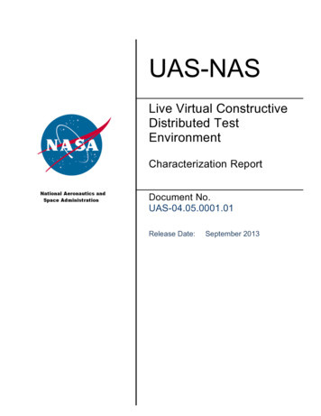
LVC SWDD-03 Rev Blive aircraft data and passing on to the LVC environment.April 20, 2015Figure 2. System Configuration 1BFigure 2 shows the architecture in support of pairwise encounters with the high speed S3 as theOwnship. The VSM interface is used as the interface for receiving the live aircraft data andpassing on to the LVC environment.3 Page
LVC SWDD-03 Rev BApril 20, 2015Figure 3. System Configuration 2Figure 3 shows a high-level diagram of the FT3 System Configuration 2. As with SystemConfiguration 1, System Configuration 2 is designed to provide connectivity among a virtualUAS GCS, constructive manned traffic generators, and virtual ATC. In this case these virtualand constructive components will be provided via facilities at NASA Langley. In addition, aflight simulator with TCAS II version 7.0 running at NASA Ames and connected via HLA willprovide the primary intruder aircraft during testing. The UAS GCS at NASA Langley willcontain a combined Virtual Simulator, the CDTI, and the SAA algorithm for testing.Note that this SWDD traces implementation to the new or revised LVC SWRD-02 Rev Crequirements for FT3 as follows. (See Section 9)1.1 Scope and OverviewThis document provides the software design description for the two core software components,the LVC Gateway, the LVC Gateway Toolbox, and two participants—the LVC Gateway DataLogger and the SAA Processor (SaaProc).4 Page
LVC SWDD-03 Rev BApril 20, 20152.0 Reference DocumentsDocument TitleDescriptionAPR-7150.2Ames Software Engineering RequirementsIT&E-CMP-001IT&E Configuration Management PlanIT&E PP-01IT&E Project PlanIT&E RMP-01UAS-NAS Risk Management PlanIT&E SAP-01IT&E Software Assurance PlanIT&E ORD-01Objectives and Requirements Document (ORD)LVC SRD-01System Requirements DocumentLVC-SWRD-02Software Requirements DocumentIT&E SDMP-01Software Development & Management PlanLVC V&VP-01LVC Verification & Validation Test PlanLVC Gateway ICD-03LVC Gateway Message Interface Control Documents5 Page
LVC SWDD-03 Rev BApril 20, 20153.0 Software Design and Development Considerations3.1 Programming languagesThe LVC Gateway software development will use C programming language and ObjectOriented Design methodology enabled by the language paradigm. The Object Orientedabstraction concept will be utilized for communication classes to capture specifics of differentclients’ interfaces as well as for configuring socket types as a TCP client or server. The designcan accommodate other protocols such as UDP, Multicast or Loopback sockets. Some of thehardware interfaces and libraries are best integrated using the C language due to thetimeframe in which these libraries were created.3.2 LVC SoftwareThe LVC is a complex system designed and developed by the combined NASA/ARC andNASA/DFRC IT&E teams to integrate with other Government off-the-shelf (GOTS) software.The processes and procedures for software development and management are described in theLVC SDMP-01 software development and management plan and the IT&E configurationmanagement process is defined in the IT&E CM Plan. This includes the typical ConfigurationChange Board (CCB) and CM processes followed at SimLabs at ARC.3.3 LVC Source Code ManagementVersion control for the LVC software is maintained using the Concurrent Versions System(CVS). Each revision of the source code will be checked into the source code configurationmanagement repository using CVS, providing complete traceability of all software changes foreach application build and executable.The LVC Gateway, LVC Gateway Data Logger, LVC Gateway Toolbox, and SaaProc softwarehave been determined to be class D software as defined in APR 7150.2.6 Page
LVC SWDD-03 Rev B4.0 System Architecture DesignApril 20, 2015The LVC Gateway functional diagram is shown in Figure 3. The LVC Gateway will integrateparticipating components that do not have the capability to connect directly to the LVCenvironment through the HLA. The LVC Gateway, and LVC Gateway Data Logger have beenmodified to handle connectivity and messaging associated with SaaProc, and Vigilant SpiritControl Station (VSCS).Figure 4. LVC System Architecture for One of the FT3 Configurations.5.0 LVC Gateway DesignHLA Middleware (COTS) and the LVC Gateway constitute the core components of the LVCsystem. The HLA LVC Gateway Toolbox will interface with the LVC Gateway as a client. Testparticipants and simulation components will connect as clients to the LVC Gateway’s socketserver. The LVC Gateway ICD-03 Rev-B provides data structures definitions in support of theproject requirements. In addition to the data structures that supported IHITL experiment, the ICDhas been updated to include SAA Omni Band and Stratway Bands messages in order to meetsystem requirements for VSCS capabilities. Upon initial network connection, each client willsend a handshake message to the Gateway defining the message types to which the client willpublish and subscribe.7 Page
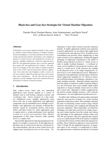
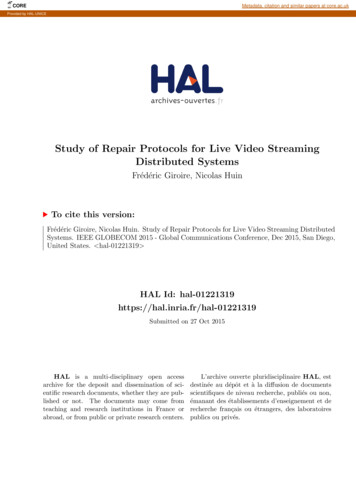
LVC SWDD-03 Rev BApril 20, 2015The ICD specifies details for data exchange between the LVC Gateway and the followingclients:- Vigilant Spirit Control Station (VSCS)- SaaProc/JADEM- CPDS/IOServer- LVC I/O (VSM)- LVC Gateway Data Logger- LVC Data Collector- Stratway /DADELIS/ADRS- LVC Gateway ToolboxThe first six clients listed above will connect to the LVC Gateway using MPI interface type onthe LVC Gateway server’s TCP socket. The client will be required to map its native datastructure to the MPI interface.The LVC Gateway connects to the Stratway interface as a client using the ADRS interface type.The ADRS client has different interface requirements. The LVC Gateway will send a periodicheartbeat message to each client to check the health of the connection. If the socket connectiondoes not reply in a timely manner due to a client process crash, process disconnect (voluntary orinvoluntary) or socket failure, the LVC Gateway will send the delete message out to the LVCsystem for tracks associated with that client.5.1 LVC Gateway Class DiagramThe Unified Modeling Language (UML) class diagram of the LVC Gateway design is shown inFigure 5. The figure depicts the software architecture representing the relationship between theclasses of the LVC Gateway.The Extensible Markup Language (XML) input configuration file is used to define the LVCGateway configuration in term of interface types, interface socket types, and data structures thatare transmitted by the LVC Gateway.The GW Client Manager class is responsible for the instantiation of all LVC Gatewaycomponents in the initialization phase of the code based on the XML configuration file. The GWClient Manager contains a collection of GW Client objects. In addition, it utilizes theobserver/observable pattern. Using this paradigm, the observable is associated with clients thatpublish messages defined in the ICD while the observer is associated with clients that subscribeto those messages.The GW Client class is an abstract class that instantiates as the MPI or ADRS interface types asdefined by the XML configuration file. Each GW Client can have many TCP and/or UDPsockets of the client and/or the server type. Each interface on the LVC Gateway side will receivethe legacy data messages such as Flight State, Flight Plan, Trajectory Intent, SAA and Trial8 Page
LVC SWDD-03 Rev BApril 20, 2015Planning data from respective participants in MPI data format. In addition to the legacymessages, two new messages are added for FT3, Saa Omni Band and Stratway Bands messages,in support of the new FT3 requirements. All messages are time stamped, buffered and thenpassed to the subscribing clients.9 Page
LVC SWDD-03 Rev BApril 20, 2015GW Client Managerw Attach(observer);w NotifySubscribers(){ foreach(observer)observer- update() }GW Client(s)base superclassw register()w update()Aggregatefinite statemachine(design pattern)AggregateAggregateInheritedXML config filepublish criteriasubscribe criteriasocket cebase superclass(concrete derived sub-classes)GWClient *x[a] new GW UASRP Client;GWClient *x[b] new GW MPI Client;GWClient *x[b] new GW ADRS Client;TcpServerSim Datadata buffering verCNetSpecs(Singletondesign pattern)scalablenew other(derived sub-clas)SocketInstance *x[a] new TcpServerSocketInstance *x[b] new UDPClientFigure 5. LVC Gateway Class Diagram10 P a g e
LVC SWDD-03 Rev BApril 20, 20155.2 Data FlowThe LVC Gateway will exchange air traffic data and the set of Sense (Detect) And Avoid(SAA/DAA) messages with live, virtual and constructive participants, as depicted in Figure 6.The VSCS will provide Flight Plan, Flight State, Trajectory Intent and Navigation Mode data.The initial Flight Plan is published as soon as the VSCS is launched while the Flight Statemessage is published periodically at the rate of 10Hz once the simulation begins operating. TheNavigation Mode message is event driven and is sent every time the pilot changes the ownship’snavigation mode between Flight Plan, Autopilot, Override and Manual modes. The VSCS willreceive a subset of the ownship’s background traffic as determined by the ownship’s sensorrange filter via the SAA Flight State message depicted in Figure 6a, b, and c. In the currentdesign, the sensor range filter is an integral part of JADEM and Stratway GCS subsystems.Constructive Flight Plan and Flight State data generated by MACS are provided through theLVC Gateway HLA Toolbox, depicted in Figure 6c. The ownship’s Flight Plan, Flight Statemessages will be sent to the LVC Gateway HLA Toolbox and on to MACS ATC displays.The SaaProc/JADEM receives Flight State message updates for constructive background trafficat 1Hz data rate. In addition, it receives all flight data including navigation mode data fromVSCS. The SaaProc also receives the Trial Trajectory Intent message published by the VSCSduring the trial planning operation at the nominal rate of 15Hz. SaaProc receives the VSCSownship Flight State message at the rate of 10Hz, then down-samples to a rate of 1Hz to matchthe data rate of the MACS constructive traffic. The new SAA Flight State message is generatedby using a sensor range filter, applied to the state data of the constructive traffic, in order toemulate a sensor proximal filter. The filtered background traffic is called “intruder traffic” whilethe state of each intruder aircraft is defined by the SAA Flight State message. The intruder trafficis published back to LVC Gateway for display on VSCS while detected intruders are also usedfor conflict detection by SAA.The SAA input is comprised of the following messages: SAA Flight State (intruders), downsampled ownship Flight State, ownship Trial Trajectory Intent and the ownship NavigationMode. The SAA algorithms calculate the following set of output SAA messages for intruders, asshown in the Figure 6a, b, and c: SAA Threat results (Alerts), SAA Resolution Maneuvers, SAAResolution Reroute and SAA Trial Threat results. All messages are defined in the LVC ICD-03.When Stratway GCS is configured with the system instead of SaaProc/JADEM, Stratway GCS receives Flight State message updates for constructive background traffic at 1Hz data rate.Stratway GCS receives the VSCS ownship Flight State message at the rate of 10Hz (thendown-samples to a rate of 1Hz to match the data rate of the MACS constructive traffic). The newSAA Flight State message is generated by using the same sensor range filter as JADEM. Theintruder traffic is published back to LVC Gateway for display on VSCS while intruders are usedfor conflict detection using Stratway algorithm. The resulting Stratway Bands message are sentto VSCS for display.11 P a g e
LVC SWDD-03 Rev BApril 20, 2015Figure 6a. Data Flow Diagram for Configuration 1A.12 P a g e
LVC SWDD-03 Rev BApril 20, 2015Figure 6b. Data Flow Diagram for Configuration 1B.13 P a g e
LVC SWDD-03 Rev BApril 20, 2015Figure 6c. Data Flow Diagram for Configuration 2.14 P a g e
LVC SWDD-03 Rev B5.3 Sequence DiagramApril 20, 2015The total of six UML sequence diagrams associated with the message flow between the LVCsystem components are shown for all three system configurations (two diagrams for eachconfiguration). The sequence diagram for the first use case for each configuration describesSaaProc/JADEM use while the second sequence diagram shown use of Stratway GCS. The firstdiagram for pairwise ownship/intruder and full mission encounter configurations are displayed inFigure 7a, 7c and 7e shows time sequence of events during the concurrent auto-resolution conflictdetection, alert level, Omni Band detections and the trial planning. The second use case withStratway in the loop for pairwise and full mission encounters are shown in Figure 7b, 7e and 7fshowing event diagrams during the Stratway Bands conflict detection.A list of the sequence of events for Configuration 1A using SaaProc/JADEM is shown below:1. The surveillance system of the live aircraft (Ikhana) will send the state data update of theownship (Ikhana) and intruders in the range of the on-board sensors to the Ikhana GCS.2. The CPDS/IOServer will receive the state data messages of the live traffic. Subsequently,IOServer will map the corresponding state data fields into the MsgFlightState messagedata structure for the ownship and intruders.3. The CPDS/IOServer will send the MsgFlightState messages for the live traffic to the LVCGateway.4. The LVC Gateway updates state data for the received traffic, including the ownshipMsgFlightState, and publishes them to SaaProc/JADEM (labeled as 1Hz Thread in thediagram) at the rate of 1Hz.5. The sensors model, which is an integral part of the SAA algorithm, determines a set ofintruders based on their 3D spatial distance from the ownship.6. SaaProc publishes only intruders back to LVC Gateway and to VSCS for display utilizingthe MsgSaaFlightState message.7. The SAA algorithm in JADEM calculates threat level for each intruder. The algorithmdetects a Self Separation (SS) threat between the ownship and intruders.8. SaaProc sends the MsgSaaThreatResult message to the LVC Gateway containing an arrayof data structures for each intruder. See ICD for details.9. The LVC Gateway forwards MsgSaaThreatResults message to VSCS to display theassociated threat level for each intruder.10. The SAA algorithm in JADEM calculates and sends to The LVC Gateway SS OmniBands for the heading and the altitude in the horizontal and vertical planes respectively.The bands are color coded advising the fly/no-fly zones for the ownship.11. The LVC Gateway sends SS Omni Bands to the VSCS display.15 P a g e
LVC SWDD-03 Rev BApril 20, 201512. The pilot (operator) performs trial planning to resolve the SS conflict by selecting the endof the heading vector attached to the ownship on the VSCS display. The pilot then rotatesthe vector around the compass rose seeking conflict free options.13. The VSCS publishes the Trial Trajectory message (MsgTrialTrajectoryIntent) at anominal rate of 15Hz to the LVC Gateway.14. The LVC Gateway forwards the Trial Trajectory message to SaaProc at a rate of 15 Hz forthe conflict assessment by the SAA Trial Planning code thread (labeled “15Hz Thread” atthe top of the diagram).Note: The two threads, SAA 1Hz and SAA 15Hz, run asynchronously performing conflictdetection calculations between each intruder and the ownship. See SaaProc section belowfor details.15. SaaProc sends the MsgSaaTrialThreatResults message to the LVC Gateway for each trialtrajectory. The message contains an array of data structures for each intruder.16. The LVC Gateway forwards MsgSaaTrialThreatResults message to the VSCS to displaythe associated threat level for each intruder.17. The pilot selects a conflict-free heading of the trial vector for the given intruder and thennegotiates the heading change with ATC. Upon receiving approval from the ATC, thepilot executes the heading maneuver by pressing the “Send” button in the VSCS UI.18. VSCS sends the MsgNavMode message to the LVC Gateway.19. The LVC Gateway forwards the MsgNavMode to both the SAA 1Hz and the SAA 15Hzthreads informing them that the ownship is now flying in the Autopilot mode vs. the FlightPlan mode prior to this maneuver.20. The process repeats from step 1 when the new traffic update arrives into SaaProc.16 P a g e
LVC SWDD-03 Rev BApril 20, 2015Figure 7a. UML Sequence Diagram: Conflict Detection using SaaProc/JADEM for Configuration 1A17 P a g e
LVC SWDD-03 Rev BApril 20, 2015Figure 7b. UML Sequence Diagram: Conflict Detection using Stratway for Configuration 1A18 P a g e
LVC SWDD-03 Rev BApril 20, 2015A list of the sequence of events for Configuration 1A using Stratway GCS is shown below:1. The surveillance system of the live aircraft (Ikhana) will send the state data update of theownship (Ikhana) and intruders in the range of the on-board sensors to the Ikhana GCS.2. The CPDS/IOServer will receive the state data messages of the live traffic. Subsequently,IOServer will map the corresponding state data fields into the MsgFlightState messagedata structure for the ownship and intruders.3. The CPDS/IOServer will send the MsgFlightState messages for the live traffic to the LVCGateway.4. The LVC Gateway updates state data for the received traffic, including the ownshipMsgFlightState, and publishes them to Stratway GCS at the rate of 1Hz.5. The sensors model, which is an integral part of Stratway , determines a set of intrudersbased on their 3D spatial distance from the ownship.6. The Stratway GCS publishes only the intruders back to the LVC Gateway and to theVSCS for display utilizing the MsgSaaFlightState message.7. The Stratway algorithm calculates no-fly bands and the threat level for each intruder.8. Stratway GCS sends the MsgStratwayBands message to the LVC Gateway. See ICD fordetails.9. The LVC Gateway forwards the MsgStratwayBands message to the VSCS to display theassociated threat level for each intruder and Stratway bands. The VSCS displays fourtypes of bands; heading, altitude, true air speed and vertical speed bands.10. The pilot selects a conflict-free heading of the vector for the given intruder and thennegotiates the heading change with ATC. Upon receiving approval from the ATC, thepilot executes the heading maneuver by pressing the “Send” button in the VSCS UI.11. The VSCS sends the MsgNavMode message to LVC Gateway.12. The process repeats from step 1 when the Ikhana issues a new traffic update.19 P a g e
LVC SWDD-03 Rev BApril 20, 2015Figure 7c. UML Sequence Diagram: Conflict Detection using SaaProc/JADEM for Configuration 1B20 P a g e
LVC SWDD-03 Rev BApril 20, 2015A list of the sequence of events for Configuration 1B using SaaProc/JADEM is shown below:1. The surveillance system of the live S-3 aircraft will send the state data update of theownship (S-3) and intruders in the range of the on-board sensors to the CNPC GroundStation and onto the VSM LVC I/O subsystem.2. The VSM LVC I/O will receive the state data messages of the live traffic. Subsequently,the LVC I/O will map the corresponding state data fields into the MsgFlightState messagedata structure for the ownship and intruders.3. The LVC I/O will send MsgFlightState messages to the LVC Gateway.4. Repeat Configuration 1A (when using SaaProc/JADEM) Steps 4-19, including the trafficsensor range filtering, Alerting, Omni Bands, and Trial planning.5. Concurrently and asynchronously, STANAG 4586 standard interface containingCommand and Control data is sent from the S-3 aircraft to CNPC GS and onto theSTANAG I/O.6. The STANAG 4586 message is sent directly to the VSCS.7. The pilot might issue a heading maneuver that will be encoded into the STANAG messagewhich will be uplinked S-3. The content of Command and Control message will bepresented to the S-3 pilots for their assessment and subsequent execution of the maneuver.8. The process repeats from step 1 when the S-3 surveillance system issues a new stateupdate.21 P a g e
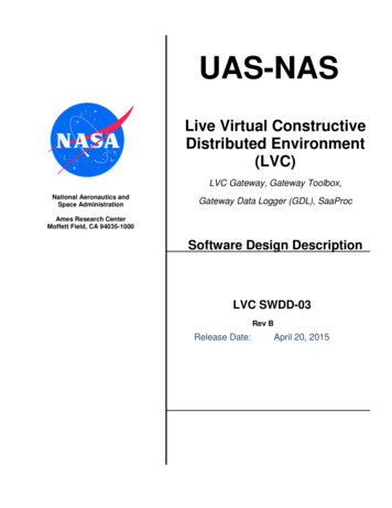
LVC SWDD-03 Rev BApril 20, 2015sd Class ModelVSM STANAG IOVSM LVC IOVSCSLVC GWStratw ay GCSS-3Receiv eFltState()VSM receives live OSand Intruder FltStates from S-3 onboard sensorsReceiv eFltState()OS and IntruderFltStates are receivedReceiv eCommControl()Receiv eCommControl()OS FltStateReceiv eFltState()SendSaaFltState()SendSaaFltState()FT3 Configuration 1b:Pairwise, High Speed, S-3DAA: StratwayOS Flt State is excludedIntruders' FltState isunconditionallypassed through thefilter of the sensormodels (ADS-B ()SendAlerts()DisplayAlerts()SendStratw ayBands()SendStratw ayBands()DisplayStratw ayBands()SetManeuv er()SendCommControl()SendCommControl()UAS GCS pilot selectsand uplinks themaneuver to UA.Figure 7d. UML Sequence Diagram: Conflict Detection using Stratway for Configuration 1B22 P a g e
LVC SWDD-03 Rev BApril 20, 2015A list of the sequence of events for Configuration 1B having Stratway GCS in the loop is shownbelow:1. The surveillance system of the live S-3 aircraft will send the state data update of theownship (S-3) and intruders in the range of the on-board sensors to the CNPC GroundStation and onto the VSM LVC I/O subsystem.2. The VSM LVC I/O will receive the state data messages of the live traffic. Subsequently,the LVC I/O will map the corresponding state data fields into the MsgFlightState messagedata structure for the ownship and intruders.3. The LVC I/O will send MsgFlightState messages to the LVC Gateway.4. Repeat Configuration 1A (when using Stratway GCS) Steps 4-11, including the trafficsensor range filtering, Stratway Bands, and Alerting.5. Concurrently and asynchronously, the STANAG 4586 standard interface containingCommand and Control data is sent from the S-3 aircraft to CNPC GCS and onto theSTANA
The LVC Gateway functional diagram is shown in Figure 3. The LVC Gateway will integrate participating components that do not have the capability to connect directly to the LVC environment through the HLA. The LVC Gateway, and LVC Gateway Data Logger have been modified to handle connectivity and messaging associated with SaaProc, and Vigilant Spirit