Transcription
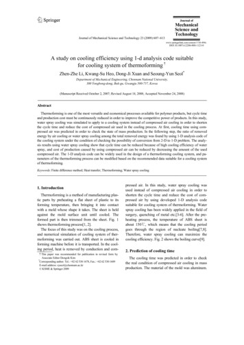
Journal ofMechanicalScience andTechnologyJournal of Mechanical Science and Technology 23 (2009) 607 613www.springerlink.com/content/1738-494xDOI 10.1007/s12206-008-1123-0A study on cooling efficiency using 1-d analysis code suitablefor cooling system of thermoforming†Zhen-Zhe Li, Kwang-Su Heo, Dong-Ji Xuan and Seoung-Yun Seol*Department of Mechanical Engineering, Chonnam National University,300 Yongbong-dong, Buk-gu, Gwangju 500-757, Korea(Manuscript Received October 2, 2007; Revised August 18, 2008; Accepted November 24, ---AbstractThermoforming is one of the most versatile and economical processes available for polymer products, but cycle timeand production cost must be continuously reduced in order to improve the competitive power of products. In this study,water spray cooling was simulated to apply to a cooling system instead of compressed air cooling in order to shortenthe cycle time and reduce the cost of compressed air used in the cooling process. At first, cooling time using compressed air was predicted in order to check the state of mass production. In the following step, the ratio of removedenergy by air cooling or water spray cooling among the total removed energy was found by using 1-D analysis code ofthe cooling system under the condition of checking the possibility of conversion from 2-D to 1-D problem. The analysis results using water spray cooling show that cycle time can be reduced because of high cooling efficiency of waterspray, and cost of production caused by using compressed air can be reduced by decreasing the amount of the usedcompressed air. The 1-D analysis code can be widely used in the design of a thermoforming cooling system, and parameters of the thermoforming process can be modified based on the recommended data suitable for a cooling systemof thermoforming.Keywords: Finite difference method; Heat transfer; Thermoforming; Water spray -----1. IntroductionThermoforming is a method of manufacturing plastic parts by preheating a flat sheet of plastic to itsforming temperature, then bringing it into contactwith a mold whose shape it takes. The sheet is heldagainst the mold surface unit until cooled. Theformed part is then trimmed from the sheet. Fig. 1shows thermoforming process[1, 2].The focus of this study was on the cooling process,and numerical simulation of cooling system of thermoforming was carried out. ABS sheet is cooled informing machine before it is transported. In the cooling period, heat is removed by conduction and com†This paper was recommended for publication in revised form byAssociate Editor Dongsik Kim*Corresponding author. Tel.: 82 62 530 1678, Fax.: 82 62 530 1689E-mail address: syseol@chonnam.ac.kr KSME & Springer 2009pressed air. In this study, water spray cooling wasused instead of compressed air cooling in order toshorten the cycle time and reduce the cost of compressed air by using developed 1-D analysis codesuitable for cooling system of thermoforming. Waterspray cooling has been widely applied in the field ofsurgery, quenching of metal etc.[3-6]. After the preheating process, the temperature of ABS sheet isabout 150 , which means that the cooling periodgoes through the region of nucleate boiling[7,8].Therefore, water spray cooling can maximize thecooling efficiency. Fig. 2 shows the boiling curve[9].2. Prediction of cooling timeThe cooling time was predicted in order to checkthe real condition of compressed air cooling in massproduction. The material of the mold was aluminum.
608Z.-Z. Li et al. / Journal of Mechanical Science and Technology 23 (2009) 607 613Fig. 3. Mold and sheet in cooling system.Fig. 1. Thermoforming process.Fig. 4. Analysis model.The calculated cooling time(tcl) was 11.6s under thecondition that the heat transfer coefficient of compressed air cooling(ha) was assumed as 80W/m2.Kwith the initial temperature(Ti) of 150 and finaltemperature(Tf) of 80 . The calculated cooling timewas reasonable compared with the cooling time inmass production(16s). In sum, the compressed aircooling is the limit of reducing the cycle time.3. Development of 1-D analysis code3.1 2-D analysisFig. 2. Boiling curve.The dimension of the mold was 2 1 0.02 (m), andthe dimension of the ABS sheet was 2 1 0.001(m), because the sheet becomes thinner after theprocess of heating and blowing. Equation 1 could beobtained when the ratio of the energy removed fromupper surface (compressed air cooling) among thetotal removed energy was assumed as 40%.0.4 ρ pThp Ap C pdT ha Ap (T Te )dt(1)Therefore, the cooling time can be calculated fromEq. 2.0.4 ρ pThp C phaln(Ti Te) tclT f Te(2)ABS sheet is cooled by compressed air and mold inmass production as shown in Fig. 3. To check thepossibility of changing a 2-D to a 1-D problem, 2-Danalysis was performed by using the commercial code- FLUENT. The distance between channels was125mm, and mold thickness was 30mm. Inner diameter of coolant channel was 4mm, and thickness ofchannel tube made of stainless steel was 0.6mm.Thickness of sheet made of ABS was assumed as3mm. Coolant temperature, initial mold temperatureand environmental temperature were 75 , 80 and30 , respectively. The heat transfer coefficients ofcoolant cooling of channel, compressed air coolingand water spray cooling were the recommended values of 500W/m2.K, 100W/m2.K, 1000W/m2.K[2,10].In analysis, contact resistance between sheet and
609Z.-Z. Li et al. / Journal of Mechanical Science and Technology 23 (2009) 607 613mold was neglected, and symmetry condition wasused to reduce the computational effort as shown inFig. 4.Table 1 shows the time-dependent temperature ofthe mold under the condition of compressed air cooling and water spray cooling. Checking point is theinner surface point of the mold at the farthest positionfrom the coolant channel. The amplitude results ofabout 2.5 under the condition of 2 cases show thattemperature condition of mold will not be changedmuch more when using water spray cooling instead ofcompressed air cooling.Table 2 and Table 3 show time-dependent temperature of each position under the condition of compressed air cooling and water spray cooling. Asshown in Table 2 and Table 3, the temperature resultsof the same position along the thickness direction ofsheet at farthest and nearest from the coolant channelwere nearly the same when the distance betweenchannels in mass production was set as 125mm.Therefore, 1-D analysis can be used to simulate thecooling process of thermoforming for simplicity.By comparing Table 2 and Table 3, it was foundthat water spray cooling can drop the temperature ofthe upper surface more quickly than compressed aircooling because of high cooling efficiency.TimeAir CoolingWater Cooling0s80.00 80.00 8s81.79 81.75 16s82.60 82.51 Table 2. Time-dependent temperature using compressed aircooling.Item0s8sPrevious 2-D analysis showed that 1-D analysis ispossible. The equivalent heat transfer coefficient ofcoolant cooling from a 2-D to a 1-D problem must becalculated.Shape factor(S) can be calculated by using Eq. 3.The distance between channels(P) was 125mm. Thedistance from upper surface of mold to the center ofcoolant channel(D) was 25mm. The calculated shapefactor was 1.69.S 2π 2P 2π D ln sinh D P (3)Using Eq. 4, the calculated equivalent heat transfercoefficient of coolant conversion from 2-D to 1-Dproblem was 2.8424 W/m2.K. The total length ofchannel(L) was 18.56m, and the diameter of channel(d) was 8mm. The thickness of mold was 25mm,and the surface dimension of sheet was 2 1 (m).11 ( Ap ) (π d L)D111 k hw equivalentπ d hw S k(4)3.3 1-D FDM analysis codeTable 1. Time-dependent temperature of mold.Upper Surface(near from channel)Upper Surface(far from channel)Center(near from channel)Center(far from channel)Lower Surface(near from channel)Lower Surface(far from channel)3.2 Conversion from 2-D to 1-D problem16s150 105.3 94.7 150 105.5 94.9 150 137.1 116.2 150 137.3 116.3 150 83.8 84.9 150 84.1 85.1 The total cooling cycle time was set as 35s, but realcooling time was 16s. In this cooling time, ABS sheetwas cooled by compressed air cooling (or water spraycooling) and conduction, while the mold was cooledby conduction and coolant cooling for 16s. The other19s was preparing time. In this period, ABS sheet isTable 3. Time-dependent temperature using water spraycooling.ItemUpper Surface(near from channel)Upper Surface(far from channel)Center(near from channel)Center(far from channel)Lower Surface(near from channel)Lower Surface(far from channel)0s8s16s150 46.0 40.3 150 46.3 40.4 150 126.5 99.3 150 126.7 99.4 150 82.2 83.0 150 82.4 83.2
610Z.-Z. Li et al. / Journal of Mechanical Science and Technology 23 (2009) 607 613Table 4. Comparing between 2-D and 1-D analysis results.ItemUpper Surface(2-D Analysis)Upper Surface(1-D Analysis)Center(2-D Analysis)Center(1-D Analysis)Lower Surface(2-D Analysis)Lower Surface(1-D Analysis)Fig. 5. Temperature-dependent specific heat of ABS.cooled by convection, and mold is cooled by naturalconvection and coolant cooling.Numerical simulation must be carried out to get thetime-dependent distribution of temperature in thesheet because of temperature-dependent specific heatof ABS, as shown in Fig. 5[11].FDM (finite difference method) was used to simulate the heat transfer. TDMA (tri-diagonal matrixalgorithm) was used to solve the problem, and iterative calculation had to be carried out because of thetemperature-dependent specific heat of ABS and coupling boundary condition between sheet and mold.The governing equation, boundary condition andinitial condition of sheet and mold are shown in Eq. 5and Eq. 6, respectively. Where ha is heat transfer coefficient of compressed air cooling or water spray cooling, hc is heat transfer coefficient caused by contactresistance between sheet and mold, hw is heat transfercoefficient of coolant, Ta is temperature in chamber,Tw is temperature of coolant, and k is thermal conductivity(W/m.K). The subscript p is ABS, m is mold,and i means initial value.PDE : ρ p C p Tp t kp 2Tp x 2BCs:hc [Tm ( Lm , t ) Tp (0, t )] k pIC : Tha [Tp ( Lp , t ) Ta ] k p xTp ( x,0) Tp iPDE : ρ mCm Tm 2T km 2m t xBCs:hc [Tp (0, t ) Tm ( Lm , t )] k mIC : Thw [Tm (0, t ) Tw ] km xTm ( x,0) Tm i T x T x8s16s105.4 94.8 107.8 93.8 137.2 116.2 136.3 118.4 83.6 85.0 82.3 83.2 Table 5. Analysis conditions of 1-D FDM model.Temperature of mold90 Temperature of coolant85 Initial temperature of sheet150 Temperature in the chamber30 Heat transfer coefficient caused by contact resistance500W/m2.KHeat transfer coefficient of coolant2.8424W/m2.KHeat transfer coefficient of compressed air cooling 100W/m2.KHeat transfer coefficient of water spray cooling1000W/m2.KHeat transfer coefficient of transportation10W/m2.KAt first, 1-D analysis result was compared with 2-Danalysis result in order to check the accuracy of theconversion from a 2-D to a 1-D problem. In 1-Danalysis, hc was given a big value in order to neglectcontact resistance as in 2-D analysis. By comparing, itwas found out that 1-D analysis code is suitable foranalyzing the cooling system of thermoforming incertain accuracy as shown in Table 4. 2-D analysisresults shown in Table 4 are the mean value of eachsurface.4. Specification of 1-D analysis condition(5)(6)Table 5 shows the analysis conditions. The temperature of mold and coolant are the average data ofmass production. The temperature of mold must bekept on the temperature shown in Table 5 because itis the most suitable temperature for forming products.The heat transfer coefficient of transportation wasassumed a little larger than the mean value of naturalconvection because the product on the moment offorming is happened overturning during transportation[12, 13].Table 6 and Table 7 show time-dependent mean
611Z.-Z. Li et al. / Journal of Mechanical Science and Technology 23 (2009) 607 613Table 6. Time-dependent mean temperature of ABS sheetunder 3 different conditions.Table 8. Calculation of the ratio removed from upper surfaceof sheet under the 3 different conditions.On the momentAir(16s)Water(16s)Water(7s) Air(9s)ItemAir(16s)Water(16s)Water(7s) Air(9s)7s131.5 114.6 114.6 0.645MJ0.973MJ0.831MJ16s116.5 93.7 113.8 Total RemovedEnergyUpper Surface0.250MJ0.566MJ0.420JM35s109.4 88.8 97.7 Ratio(%)38.758.150.5Table 7. Time-dependent temperature of mold under 3 different conditions.On the momentAir(16s)Water(16s)Water(7s) Air(9s)7s91.2 91.2 91.2 16s92.1 92.0 92.0 35s91.8 91.7 91.7 temperature of ABS sheet and temperature of mold atspecified time under the condition of compressed aircooling, water spray cooling and the combined waterand air cooling, respectively.As shown in Table 6, water spray cooling can dropthe surface temperature faster than the others becauseof high cooling efficiency.Table 7 shows that mold temperature will not bechanged much more when the other cooling methodis applied. This is very important because mold mustbe modified if the temperature condition is changedmuch more.The total energy removed from the sheet can becalculated by using Eq. 7. Where Vp is volume ofsheet(m3)Qremoved ρ V p C p (T f mean Ti )(7)The removed energy from the upper surface ofsheet can be calculated by Eq. 8.16Q Ap q (T )dT0(8)The calculated ratio of the energy removed fromupper surface among the total removed energy underthe three different conditions is shown in Table 8. Theefficiency of water spray cooling was the best one ofthe three different conditions, but the merit of thecombination of water and air cooling is that it canremove the rest of the sprayed water droplets withgood cooling efficiency. Also, the cooling efficiencyof water spray is not so high when the temperature ofthe sheet surface is lower than the saturation temperature, so the combination of water spray cooling andcompressed air cooling is the best candidate.If the parameters of spray cooling such as velocityof droplet, diameter of droplet etc. are adjusted, theefficiency of the cooling can be improved[14].The 1-D analysis code can be widely used in thedesign of a thermoforming cooling system, and parameters of the thermoforming process can be modified based on the recommended data suitable for thecooling system of thermoforming.5. ConclusionsThe analysis code which can be used to simulatethe process of cooling has been developed. In order toshorten cycle time and reduce the cost of production,water spray cooling was simulated to apply to thecooling system of thermoforming. To check the stateof mass production, cooling time using compressedair was predicted at first. To compare the coolingefficiency of compressed air cooling and water spraycooling, the ratio of removed energy from upper surface of sheet among the total removed energy wascalculated by using the developed 1-D analysis codeof the cooling process under the condition of checking the accuracy of 1-D analysis code by comparingwith the 2-D result. The analysis results using waterspray cooling show that cycle time can be reducedbecause of high cooling efficiency of the water spray,and the cost of production can be reduced by decreasing the amount of the compressed air -------------------------ACpdDhArea, m2Specific heat, kJ/kgKDiameter of coolant channel, mDistance between center of coolant channeland upper surface of mold, m: Heat transfer coefficient of convection,::::
612hfgkLmm PqQStTThZ.-Z. Li et al. / Journal of Mechanical Science and Technology 23 (2009) 607 613::::::::::::W/m2KLatent heat of water, 2257kJ/kgThermal conductivity, W/mKTotal length of coolant channel, mMass, kgMass flow rate, kg/sDistance between channels, mHeat flux, W/m2Heat flow rate, WShape factorTime, sTemperature, Thickness, mGreek Symbolsρ: Density, EnvironmentFinalInitialMoldSheetWaterReferences[1] M. K. Warby, J. R. Whiteman, W. G. Jiang, P.Warwick and T. Wright, Finite element simulationof thermoforming processes for polymer sheets,Mathematics and Computers in Simulation 61 (3-6)(2003) 209-218.[2] J. L. Throne, Technology of Thermoforming, Hanser Publishers, Munich, New York, USA, (1987).[3] G. Aguilar, B. Majaron, K. Pope, L. O. Svaasand, E.J. Lavernia and J. S. Nelson, Influence of nozzle-toskin distance in cryogen spray cooling for dermatologic laser surgery, Lasers in Surgery and Medi-cine 28 (2) (2001) 113-120.[4] Q. Cui, S. Chandra and S. McCahan, The effect ofdissolving salts in water sprays used for quenching a hot surface. Part 2: spray cooling, Journal ofHeat Transfer 125 (2) (2003) 333-338.[5] Y. Mitsutake, M. Monde, Y. Kojima and A. Mikami, Characteristics of transient heat transfer on ahot surface during cooling with spray, Thermal Science and Engineering 12 (4) (2004) 41-42.[6] J. A. Clements and S. A. Sherif, Thermal analysisof roof spray cooling, International Journal of Energy Research 22 (15) (1998) 1337-1350.[7] S. S. Hsieh, T. C. Fan and H. H. Tsai, Spray coolingcharacteristics of water and R-134a. Part I: nucleateboiling, International Journal of Heat and MassTransfer 47 (26) (2004) 5703-5712.[8] J. Yang, L. C. Chow and M. R. Pais, Nucleate boiling heat transfer in spray cooling, Journal of HeatTransfer 118 (3) (1996) 668-671.[9] F. P. Incropera and D. P. Dewitt, Fundamental ofHeat and Mass Transfer, John Wiley & Sons, NewYork, USA, (1996).[10] A. Bejan, Convection Heat Transfer, John Wiley& Sons, New York, USA, (1995).[11] Z. Z. Li, K. S. Heo and S. Y. Seol, Timedependent optimal heater control in thermoformingpreheating using dual optimization steps, International Journal of Precision Engineering and Manufacturing 9 (4) (2008) 51-56.[12] R. J. Goldstein, E. M. Sparrow and D. C. Jones,Natural convection mass transfer adjacent to horizontal plates, Int. J. Heat and Mass Transfer 16(1973) 1025-1037.[13] J. R. Lloyd and W. R. Moran, Natural convectionadjacent to horizontal surfaces of various planforms, Journal of Heat Transfer 96 (1974) 443-451.[14] B. M. Pikkula, J. W. Tunnell, D. W. Chang and B.Anvari, Effects of droplet velocity, diameter, andfilm height on heat removal during cryogen spraycooling, Annals of Biomedical Engineering 32 (8)(2004) 1131-1140.
Z.-Z. Li et al. / Journal of Mechanical Science and Technology 23 (2009) 607 613Zhen-Zhe Li received his B.S.degree in Mechanical Engineering from Yanbian University, China, in 2002. He thenreceived his M.S. degree inAerospace Engineering fromKonkuk University, SouthKorea, in 2005. He then received his Ph.D. degree in Mechanical Engineeringfrom Chonnam National University, South Korea, in2009. Dr. Li is currently a Researcher of the Department of Mechanical Engineering, Chonnam NationalUniversity, South Korea. Dr. Li’s research interestsinclude applied heat transfer, fluid mechanics andoptimal design of thermal and fluid systems.Kwang-Su Heo received hisB.S. degree in MechanicalEngineering from ChonnamNational University, SouthKorea, in 1998. He thenreceived his M.S. and Ph.D.degrees in Mechanical Engineering from Chonnam National University, South Korea, in 2003 and 2008,respectively. Dr. Heo is currently a Post-doctorialResearcher of the Department of Mechanical Engineering, KAIST(Korean Advanced Institute of Science and Technology), South Korea. Dr. Heo’s research interests include applied heat transfer, fluidmechanics and thermal analysis of superconductor.613Dong-Ji Xuan received his B.S.degree in Mechanical Engineering from Harbin Engineering University, China, in2000. He then received his M.S.degree in Mechanical Engineering from Chonnam National University, South Korea,in 2006. He is currently a Ph.D. candidate of the Department of Mechanical Engineering, Chonnam National University, South Korea. His research interestsinclude control & optimization of PEM fuel cell system, dynamics & control, mechatronics.Seoung-Yun Seol received hisB.S. degree in MechanicalDesign from Seoul NationalUniversity, South Korea, in1983. He then received his M.S.degree in Mechanical Engineering from KAIST(KoreanAdvanced Institute of Scienceand Technology), South Korea, in 1985. He then received his Ph.D. degree in Mechanical Engineeringfrom Texas Tech University, USA, in 1993. Dr. Seolis currently a Professor of the School of Mechanicaland Systems Engineering, Chonnam National University, South Korea. Dr. Seol’s research interestsinclude applied heat transfer, fluid mechanics andthermal analysis of superconductor.
Thermoforming is a method of manufacturing plas-tic parts by preheating a flat sheet of plastic to its forming temperature, then bringing it into contact with a mold whose shape it takes. The sheet is held against the mold surface unit until cooled. The formed part is then trimmed from the sheet. Fig. 1 shows thermoforming process[1, 2].