Transcription
DRAFT UGANDA STANDARDDUS DEAS 928-1First Edition2018-mm-ddPUBLICREVIEWDRAFTHot applied thermoplastic road marking paint — Specification,Part 1: Constituent material and mixturesReference numberDUS DEAS 928-1: 2018 UNBS 2018
DUS DEAS 928-1: 2018Compliance with this standard does not, of itself confer immunity from legal obligationsPU UNBS 2018BLICREVIEWDRAFTA Uganda Standard does not purport to include all necessary provisions of a contract. Users areresponsible for its correct applicationAll rights reserved. Unless otherwise specified, no part of this publication may be reproduced or utilised in anyform or by any means, electronic or mechanical, including photocopying and microfilm, without prior writtenpermission from UNBS.Requests for permission to reproduce this document should be addressed toThe Executive DirectorUganda National Bureau of StandardsP.O. Box 6329KampalaUgandaTel: 256 417 333 250/1/2Fax: 256 414 286 123E-mail: info@unbs.go.ugWeb: www.unbs.go.ugii UNBS 2018 - All rights reserved
DUS DEAS 928-1: 2018National forewordUganda National Bureau of Standards (UNBS) is a parastatal under the Ministry of Trade, Industry andCooperatives established under Cap 327, of the Laws of Uganda, as amended. UNBS is mandated to coordinate the elaboration of standards and is(a) a member of International Organisation for Standardisation (ISO) and(b) a contact point for the WHO/FAO Codex Alimentarius Commission on Food Standards, and(c) the National Enquiry Point on TBT Agreement of the World Trade Organisation (WTO).AFTThe work of preparing Uganda Standards is carried out through Technical Committees. A TechnicalCommittee is established to deliberate on standards in a given field or area and consists of representatives ofconsumers, traders, academicians, manufacturers, government and other stakeholders.DRDraft Uganda Standards adopted by the Technical Committee are widely circulated to stakeholders and thegeneral public for comments. The committee reviews the comments before recommending the draft standardsfor approval and declaration as Uganda Standards by the National Standards Council.IEWThis Draft Uganda Standard, DUS DEAS 928-1: 2018, Hot applied thermoplastic road marking paint —Specification — Part 1: Constituent material and mixtures, is identical with and has been reproduced from anInternational Standard, DEAS 928-1: 2018, Hot applied thermoplastic road marking paint — Specification —Part 1: Constituent material and mixtures, and is being proposed for adoption as a Uganda Standard.REVThis standard was developed by the Chemicals and environment Standards Technical Committee (UNBS/TC5).PUBLICWherever the words, “East African Standard " appear, they should be replaced by "Uganda Standard." UNBS 2018 - All rights reservediii
DEAS 928-1: 2018ICS 87.040AFTDRAFT EAST AFRICAN STANDARDPUBLICREVIEWDRHot applied thermoplastic road marking paint — Specification, Part 1:Constituent material and mixturesEAST AFRICAN COMMUNITY EAC 2018First Edition 2018
ICPUBLREVIEWAFTRD
DEAS 928-1: 2018Copyright noticeThis EAC document is copyright-protected by EAC. While the reproduction of this document byparticipants in the EAC standards development process is permitted without prior permission from EAC,neither this document nor any extract from it may be reproduced, stored or transmitted in any form forany other purpose without prior written permission from EAC.Requests for permission to reproduce this document for the purpose of selling it should be addressedas shown below or to EAC’s member body in the country of the requester:AFT East African Community 2018 — All rights reservedEast African CommunityP.O. Box 1096,ArushaTanzaniaTel: 255 27 2162100Fax: 255 27 2162190E-mail: eac@eachq.orgWeb: www.eac-quality.netPUBLICREVIEWDRReproduction for sales purposes may be subject to royalty payments or a licensing agreement.Violators may be prosecuted.ii EAC 2018 – All rights reserved
DEAS 928-1: 2018ForewordDevelopment of the East African Standards has been necessitated by the need for harmonizing requirementsgoverning quality of products and services in the East African Community. It is envisaged that throughharmonized standardization, trade barriers that are encountered when goods and services are exchangedwithin the Community will be removed.The Community has established an East African Standards Committee (EASC) mandated to develop andissue East African Standards (EAS). The Committee is composed of representatives of the NationalStandards Bodies in Partner States, together with the representatives from the public and private sectororganizations in the community.AFTEast African Standards are developed through Technical Committees that are representative of keystakeholders including government, academia, consumer groups, private sector and other interested parties.Draft East African Standards are circulated to stakeholders through the National Standards Bodies in thePartner States. The comments received are discussed and incorporated before finalization of standards, inaccordance with the Principles and procedures for development of East African Standards.REast African Standards are subject to review, to keep pace with technological advances. Users of the EastAfrican Standards are therefore expected to ensure that they always have the latest versions of the standardsthey are implementing.DThe committee responsible for this document is Technical Committee EASC/TC 070, Paints, varnishes andrelated products.REVIEWAttention is drawn to the possibility that some of the elements of this document may be subject of patentrights. EAC shall not be held responsible for identifying any or all such patent rights.During the preparation of this Standard, reference was made to the following document: .PUBLICAcknowledgement is hereby made for the assistance derived from this source. EAC 2018 – All rights reservediii
ICPUBLREVIEWAFTRD
DRAFT EAST AFRICAN STANDARDDEAS 928-1: 2018Hot applied thermoplastic road marking paint — Specification, Part 1:Constituent material and mixtures1Scope2AFTThis Draft East African Standard prescribes the requirements, methods of sampling and test for hot appliedthermoplastic road marking paint and constituents that are melted and applied by spray, screed or extruded.Normative referencesREVIEWDEAS 927:2018, Road marking paints— SpecificationDRThe following documents are referred to in the text in such a way that some or all of their content constitutesrequirements of this document. For dated references, only the edition cited applies. For undated references,the latest edition of the referenced document (including any amendments) applies.ISO 4618, Paints and varnishes — Terms and definitionsISO 591-1, Titanium dioxide pigments for paints part 1: Specification and Method of testISO 15528, Paints, varnishes and raw materials for paints and varnishes — SamplingICBS 598-2, Sampling and examination of bituminous mixtures for roads and other paved areas/Methods foranalytical testingPUBLBS 812-103, Testing aggregatesBS 1994, Specification for dichloromethane (methylene chloride)EN 1423, Road marking materials. Drop on materials. Glass beads, antiskid aggregates and mixtures of thetwo3Terms and definitionsFor the purposes of this document, the following terms and definitions apply.3.1aggregatea granular material of mineral composition, such as calcite, quartz or flint, used to provide bulk ofthermoplastic road marking material3.2bindera thermoplastic resinous material which, with any included oils or other plasticers, provide adhesion to theroad surface and cohesion between the other components. EAC 2018 – All rights reserved1
DEAS 928-1: 20183.3extendera powder added to assist the dispersion of the pigment and impart body to the mixture.3.4luminance factorthe ratio of the luminance of a reflecting surface in a given direction to that of the ideal white diffusing surface,when viewed in same direction and illuminated in the same way, expressed as a percentage3.5retroreflectivitythe property of some material such as solid glass beads, to reflect incident light in direction close to thedirection from which it cameAFT3.6thermoplasticsa solvent-free marking substance supplied in block, granular or powder forms. It’s heated to a molten stateand then applied with appropriate hand or mechanical applicator. It forms cohesive films by coolingDR3.7thermoplastic road marking materiala material consisting of aggregate, pigment, binder, glass beads and extenders, capable of being softened byheating and hardened by cooling, which is used for road markingREVIEW3.8softening pointis the temperature at which a given layer of thermoplastic material experiences a given deformation under theaction of steel balls of 13.9 gRequirements4.14.1.1PUBL4IC3.9no pick-up timethe period, determined by the procedure described in Annex C of CD/K/5:2018, between application of a paintand the moment when the paint just ceases to be removed by a simulated tyre of a vehicle passing over thepainted surfaceGeneral requirementsAggregate4.1.1.1 For white and yellow thermoplastic, the aggregate shall consist of light coloured and sand, calcite,quartz or calcined flint.4.1.1.2 For black thermoplastic, calcined bauxite or other dark coloured aggregate may be used and pigmentmay be predisposed.4.1.2BinderThe binder shall comprise plasticised synthetic resin, plasticised natural resin or rosins.4.24.2.12Specific requirementsThe Hot applied thermoplastic road marking paint shall comply with requirements in Table 1 below. EAC 2018 – All rights reserved
DEAS 928-1: 2018Table 1 — Specific requirements for Hot applied thermoplastic road marking paintSl. No.characteristicRequirementTest methodYellowWhiteOthercoloursLuminance factor,%.48 - 5270,minTBDAnnex A and Bii)Heat stability, min.4565TBDAnnex A and Biii)Softening point, C, min.85Annex Civ)Flow resistance at 40 C, %,max.25Annex Dv)no pick-up timeShall complyAnnex A and Annex Evi)Pigment, TitaniumTitanium dioxide (TiO2) of theanatase or the rutile crystalstructure,ISO 591-1,vii)ReflectorizationClass AEN 1423DRAFTi)REVIEWincorporated into marking materialprior to the application on the roadsurfaceClass BSolid glass beads for additionalsurface reflectorization4.2.2Total Lead content, max.90ppmISO 6503Composition of the marking materialICviii)PUBL4.2.2.1When the sample of the marking material is tested in accordance with Annexes E and F, theproportion of the constituents of the mixture shall be in accordance with Table 2.Table 2 — Proportion of constituents of marking materialSl. No.ConstituentsPercentage (%)i)Binder ( Resin and oil)20 2ii)Solid glass beads20 minimumiii)Aggregatetogetherwithpigmentsextender and solid glass beads‒Note: At least 20 % by mass, may be maintained even in case the material to which solid glass beads aresurface applied by pressure or gravity. Black material to be non-reflectorized and the binder to be 19 3 bymass of the total mixture. EAC 2018 – All rights reserved3
DEAS 928-1: 201855.1Packaging and LabellingPackagingThe thermoplastic road marking paint and mixture shall be packaged in a suitable container that prevents itfrom deterioration during storage, transportation and normal handling5.2LabellingThe labelling shall be either in English, Kiswahili or French or in combination as agreed between themanufacturer and / or the supplier. Any other language is optional.i)the words “hot applied thermoplastic road marking paint;ii)name and address of the manufacturer;AFTEach package shall be legibly and indelibly marked with the following information.Riii) net contents by mass in kilograms;best before date ;vi) colour of the material;REVIEWv)Div) date of manufacturevii) instructions for use, disposal and safety requirements.viii) maximum safe heating temperature;6SamplingICix) batch number.PUBLSampling shall be done in accordance to ISO 15528.4 EAC 2018 – All rights reserved
DEAS 928-1: 2018Annex A(normative)Determination of heat stability of thermoplastic materialA.1 PrincipleHeat stability for the thermoplastic material is determined by measuring the luminance factor after heating thematerial for extended period. The material is heated at 200 0C for 6 h; the luminance factor is then measured.A.2 ApparatusAFTA.2.1 Heating device, an oil bath or suitable recessed aluminium block on a hotplate capable of maintainingthe sample at 200 C 3 C.RA.2.2 Paddle stirrer, electrically driven capable of continuously stirring the molten sample at 150 10r/minute. The shaft of the stirrer shall have a 6.5 mm diameter rod of suitable length to fit stirrer motor which isfitted with a single blade paddle of 40 0.5 length and 1.5 mm 0.5 mm thickness.DA.2.3 Beaker, of heat resistant glass with capacity of 250 mL and having nominal dimensions 110 mm high 65 mm diameter.REVIEWA.2.4 Light source, a tungsten lamp operating at a correlated colour temperature of 2 854 K.A.2.5 Photoelectric cell, having a spectral sensitivity closely matched to CIE photopic luminous efficiencyfunction V (X) when two curves are normalized at 555 nm.A.2.6 Magnesium carbonate block, calibrated against magnesium oxide. A new surface should be preparedbefore use.ICA.2.7 Mould of silicon rubber, approximately 100 mm in diameter to cast sample discs.PUBLA.2.8 Balance, capable of weighing up to 300 g to an accuracy of 1 g.A.3 Procedure for preparation of test materialA.3.1 GeneralTest material shall be prepared in accordance with A.2.2, for powdered material or A.2.3 for block orperformed material.A.3.2 Powdered materialA minimum of 2.5 kg of sampled material shall be prepared in an oven or on hot plate.A.3.2.1 Oven heatingPreheat the oven to a temperature of 200 C and place the sample in the oven. After 20 min, subsequently at10 to 15 min intervals, remove the sample from the oven and place in the fume cupboard, quickly stirthoroughly with a spatula, measure the temperature, and replace the sample in the oven. When thetemperature of the sample reaches 185 C 5 C and its homogeneous, pour the material onto the mould orsurface such as test panel, pour a test specimen in accordance with A.3.4. The time from commencement ofheating to pouring shall not exceed 2 h. EAC 2018 – All rights reserved5
DEAS 928-1: 2018If the sample is not homogeneous at 185 C 5 C, raise the oven temperature to 22 0 C 10 C. Continueheating, remove the sample at 10 to 15 min intervals and stir and measure the temperature as in step (a).When the sample is homogeneous pour onto the mould or surface such as test panel, pour the sample inaccordance with A.3.4.If the sample is not homogeneous at 220 C 10 C, reject the batch.Report the temperature at pouring and at the time from first commencement of heating to pouring.A.3.2.2 Hot plate heatingAFTPreheat the hot plate to a surface temperature of 250 C to 270 C and place at least 2.5 kg of the test samplein a suitable container on the hot plate. Stir continuously to ensure homogeneity and even heating andmeasure the temperature at 5 min interval. When the temperature of the sample reaches 185 C 5 0C andthe sample is homogeneous, pour the material onto the mould or surface such as test panel, pour the samplein accordance with A.3.4.RIf the sample is not homogeneous at 185 C 5 C, continue heating, remove the sample at 5 min intervalsand stir and measure the temperature as in A.3.2.2. When the sample is homogeneous, pour into mould orsurface such as test panel, pour test specimen in accordance with A.3.4DA.3.3 Block material or preformed materialREVIEWA minimum of 2.5 kg of sample material shall be prepared in a oven or hot plate as below.A.3.3.1 Take the block sample and without the application of heat, prepare a subsample by breaking up asufficient number of pieces of material, each weighing not more than 50 g.A.3.3.2 Follow the procedure described in A.3.2, except that the time from commencement of heating topouring shall not exceed 1 h. Stir thoroughly before pouring the appropriate specimens for testing.A.3.4 Preparation of test specimenPUBLICA.3.4.1 If not already at pouring temperature, heat thermoplastic material prepared to a temperature of 185 C 5 0C and mix to an even consistency.A.3.4.2 Pour the thermoplastic material onto a test panel until a disk of approximately 100 mm diameter andthickness of 2 mm is formed. Determine the luminance factor in accordance to Annex C of CD/K/O5:2018.6 EAC 2018 – All rights reserved
DEAS 928-1: 2018Annex B(normative)Determination of luminance factorB1 PrincipleThe principle of the method is photoelectric comparison of the luminance of the test paint relative to that of aperfect reflecting diffuser. In this standard, magnesium carbonate or a white tile, calibrated against a perfectreflecting diffuser, is used as the reference surface.B2. Apparatus and materialsB2.1 Light source, a tungsten lamp operating at a correlated colour temperature of 2 854 K in a photometer.AFTB2.2 Photoelectric cell, having a spectral sensitivity closely matched to the CIE photopic luminousefficiency function V(λ).RB2.3 Magnesium carbonate block, calibrated against a perfect reflecting diffuser. Prepare a new surfaceimmediately before use.REVIEWDB2.4 Calibrated white reference tile, having a CIE value in the range 70 to 95, and a calibration against aperfect reflecting diffuser traceable to a national accredited laboratory.B2.5 Glass test pannel, as described in Annex A (for Method 1 only).B3. ProcedureB3.1 Method 1: Test panelsICB3.1.1 Prepare the glass test panel (B2.5) and apply the paint by the method described in Annex A.PUBLB3.1.2 Calibrate the apparatus with the light source (B2.1), with the axis of the incident beam at 45 1 tothe reference surface (B2.3 or B2.4). Locate the photoelectric cell (B2.2) such that the axis of the cell is at 90 1 to the illuminated reference surface. If using a magnesium carbonate block, calibrate on the mean ofreadings from three different areas.Calculate the absolute value M by use of the appropriate calibration factor.B3.1.3 Measure the luminance of three different areas of the paint film using the same geometry as in B3.1.2.Calculate the mean luminance L.B3.2 Method 2: Road trialsB3.2.1 Clean an area of each non-reflectorized paint stripe (prepared as described in H2.6) at a distance of500 mm 75 mm from the near side kerb, by the method described in J2.1, and allow to dry.B3.2.2 Taking precautions to shield the photoelectric cell from stray incident light, carry out the proceduredescribed in B3.1.2 and B3.1.3, but measure the luminance at only one location on the paint stripe. Measurethe luminance five times, rotating the cell through approximately with minimal lateral displacement betweeneach measurement.Calculate the mean L of the five measurements. EAC 2018 – All rights reserved7
DEAS 928-1: 2018B4. CalculationCalculate the luminance factor as the ratio L/M and express it as a percentage.B5. Test reportPUBLICREVIEWDRAFTThe test report shall state the luminance factor L/M to the nearest 1 %.8 EAC 2018 – All rights reserved
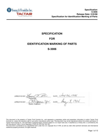
DEAS 928-1: 2018Annex C(normative)Determination of the softening pointC.1 PrincipleThe principle of this method is to determine the softening point of the thermoplastic road materials inaccordance with Wilhelmi.C.2 ApparatusC.2.1 Ring, in accordance with Wilhelmi (see Figure C.1), consisting of a bottom ring half and a top ring halfwith bayonet catch, retaining rod and prominently protruding nipplesBeaker, appropriate form for the equipmentC.2.3Steel ball mass, 13.9 0.1 g (approximate diameter 15 mm)C.2.4Thermometer, 30 C 200 C graduated in 0.5 C divisionsC.2.5Base plate of metal glassC.2.6Mould parting agent, e.g. mixture of glycerine and dextrine in 1:1 ratioC.2.7KnifeC.2.8Tongs or tweezers, for holding the ballC.2.9Test liquids, freshly boiled distilled water, glycerineREVIEWDRAFTC.2.2PUBLC.3 SamplesICC.2.10 Device for heating the beaker, enabling the temperature of the test liquid to be raised uniformly from5 C to 180 C at a rate of 5 C per 60 s 5 s and with stirring if necessary to maintain a constant heating rate.The sample mass shall amount to approximately 50 g. Two test specimens shall be tested.C.4 Preparation of the ringHeat the bottom half of the ring and base plate, thinly coated with the mould parting agent, together with thesample to the manufacturer’s suggested softening point 70 C.Fill the bottom half of the ring with the hot material. Place the top of the ring onto the bottom half so that thesuperfluous portion of the material is pressed out of that whole of the top half and leave standing for 30 min atroom temperature (18 C to 28 C). The salient portion of the test specimen is trimmed off with the warmedknife so that the surface of the test specimen is smooth and flat.Insert the bottom half of the ring into the top half and fasten with the bayonet catch. The test specimen is nowfirmly clamped between the halves of the ring, and is not capable of becoming deforming at the edges. EAC 2018 – All rights reserved9
PUBLICREVIEWDRAFTDEAS 928-1: 2018Figure C.1 — Ring in accordance with WilhelmiC.5 ProcedureSuspend the ring, after preparation as in Clause C.4, the beaker in such a way that its bottom face is situated50 mm above the bottom of the beaker. Pour the test liquid into the beaker up to a height of 50 mm above thetop face of the ring a temperature of approximately 5 C or 30 C respectively according to the test liquid used(see Table C.1). Place the ball in the test liquid but not on the test specimen. Suspend the thermometer in thebeaker in such a way that its bottom end lies flush with the bottom face of the ring, but does not touch eitherthe ring or the beaker.The type of test liquid and the initial temperature will depend of the softening point of the sample and are listedin Table C.1.10 EAC 2018 – All rights reserved
DEAS 928-1: 2018Table C.1 — Test conditionsSoftening point in accordancewith WilhelmiTest liquidInitial temperatureUp to 80 CFreshly boiled distilled water5 COver 80 CGlycerine30 CNOTEFreshly boiled distilled water should be used otherwise the test results may be affected by air bubbles.Glycerine is so viscous at temperature below 50 C that streaks are found during the heating process. However theprescribed uniform temperature rise ensures that no difficulties will occur at temperature above 60 C.AFTC.5.1 After immersion of the ball, leave the beaker standing for 10 min at room temperature (18 C to 28 C)on the beaker heating devise, which has not yet been switched on.RC.5.2 After 10 min, place the ball on the test specimen in the middle of the ring, with aid of tongs ortweezers.DC.5.3 Heat the beaker in such way that the temperature of the test liquid increases uniformly at a rate of 5 C per minute without non-turbulent stirring. Use the first few minutes to adjust the rate of temperature rise.REVIEWC.5.4 At temperature which is at least 15 C below the softening point of the sample, adjust the rate of thetemperature rise with sufficient accuracy to ensure that the further rate of temperature rise from this pointonwards takes place at 5 C per 60 s 5 s.C.5.5 Deviations shall only occur within the range of these 5 s and shall even not be compensated duringthe progress of test.ICC.5.6 As the temperature increases, the test specimen becomes more cambered in a downward directionunder weight of the ball. At instant when either the test specimen or ball comes into contact with bottom of thebeaker read of the temperature at nearest 0.5 C.PUBLC.5.7 Test the specimen in the second heating process. If the temperatures measured differ from oneanother by more than the permissible 2 C, the repeat the test on two new specimens. Carry out the testprocedure within 48 h of test specimen preparation.C.6 Expression of resultsReport the mean value of the two measurements rounded to the nearest 1 C. This represents the softeningpoint in accordance with Wilhelmi. Check for compliance with 4.3. EAC 2018 – All rights reserved11
DEAS 928-1: 2018Annex D(normative)Determination of flow resistanceD.1 PrincipleTwo conical test specimens are held at 40 C for 48 h and the percentage reduction in height is calculated.D.2 ApparatusD.2.1 Hot box, a room, container or oven which may be controlled at 40 C 2 C for 48 h.D.2.2 Measuring devise, capable of measuring the height of the test cones in mm.AFTD.2.3 Metal cones, two split or hinged conical metal moulds, of height 100 5 and with an included anglenominally 60 C at the apex, open at the base.DRD.3 ProcedureREVIEWD.3.1 Heat sufficiently the test material to 90 C 5 C above its softening point.D.3.2 Cast two conical specimens of the material so that each has an angle of nominally 60 at its apex andvertical height of 100 mm 5 mm.D.3.3 Measure and record the height of the cone to the nearest millimetre.D.3.4 After 24 h at the room temperature, remove each specimen from its mould and place upwards on a flatlevel surface in the hot box maintained at a temperature of 40 C 5 C.PUBLD.4 CalculationICD.3.5 Measure and record the height of the cone after a period of 48 h conditioning in the hot box.Calculate the decrease in height of two specimens as a percentage, to the nearest 0.1 %, and calculate theaverage of the two results as the mean slump and check for compliance Table 112 EAC 2018 – All rights reserved
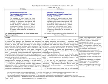
DEAS 928-1: 2018Annex E(normative)No pick-up time testE.1 PrincipleTwo rubber rings, simulating the tyres of a vehicle, are rolled over a test panel 15 min after application of thepaint. The surfaces of the rings are examined for pick-up of the paint.E.2 Apparatus and materialsE2.2AFTE2.1Steel cylinder, fitted with two replaceable O-rings (E2.2) and with a steel rod serving as an axle. Thetotal mass of the assembly, complete with O-rings, shall be 5.40 0.03 kg. The dimensions of the steelcylinder shall be in accordance with Figure 1, subject to a tolerance of 0.1 mm.O-rings, made of synthetic rubber of rubber-like material. The dimensions of the O-rings shall be:c) Cross section:D85.7 mm;9.5 mm.REVIEWb) Inside diameter:Ra) Outside diameter: 104.8 mm;E2.3Ramp, having dimensions in accordance with Figure 1, subject to a tolerance of 0.1 mm.E2.4Glass test panel, 100 mm x 200 mm in area , and 3 mm in thickness, as described in Annex B.E.3 ProcedurePUBLICCarry out the test at a temperature of 23 2 C and 50 5 % relative humidity. Prepare the glass test panel(E2.4) by the method described in Annex B to give a film of width not less than 75 mm. Record the time ofapplication.Put the painted glass panel against the ramp (E2.3) and 30 min after the application of the paint; allow thesteel cylinder (E2.1) to roll freely down the inclined ramp and over the paint film. Examine the rubber O-ringson the cylinder and record whether any of the paint is adhering to them.E.4 Test reportBoth rings shall be free from adhering paint after 30 min of application. EAC 2018 – All rights reserved13
AFTDEAS 928-1: 2018PUBLICREVIEWDRFig.1 — Apparatus for no pick-Up Time Test14 EAC 2018 – All rights reserved
DEAS 928-1: 2018Annex F(normative)Determination of binder contentF.1 ApparatusF.1.1 Metal bottle, having a capacity of between 600 ml and 2000 ml with a wide mouth and suitableclosures.Rotating machine, which will rotate the bottle about its longitudinal axis at a speed of 20 r/min 10F.1.3Volumetric flasks, of appropriate capacity, e.g. 250-ml, 500-ml and 1000-ml.AFTF.1.2r/min.F.1.4 Centrifuge or filtration apparatus, the centrifuge capable of developing an acceleration of25000 m/s2 100 m/s2 calculated in accordance with the following equation:where,DRa 1 .097 n2 r x 10-5is the number of revolutions per min;ris the radius (in mm) to the inside base of the tube when rotating.REVIEWnThe tubes shall be closed with caps to prevent loss of solvent during centrifuging.NOTE 1A typical centrifuge suitable for this method carries two or more buckets fitted with centrifuge tubes ofbetween 50 m Land 100-ml capacity.ICNOTE 2It is strongly recommended that the speed of rotation should be verified regularly to ensure that the centrifugemaintains its performance at all times.PUBLThe filtration apparatus comprises a metal bottle as specified in F.1.1, a porous filter thimble, tubing and a 50mL burette. The porous filter is of porcelain, alumina or similar material, 90 mm long by 20 mm diameter andof up to 4 µm pore diameter. The filter is closed by sealing in, to within 5 mm of the bottom, a length of metaltubing, approximately 300 mm long by 5 mm bore, that passes through a supporting ring of cork or metal thatis mounted just inside the open end of the filter. A cement paste composed of copper oxide powder, preparedby the direct oxidation of copper wire, of about 425 µm particle size, and phosphoric acid is used to seal thejoint. The joint is left to dry for a few hours. Alternatively, a rubber stopper may be used. Care has to be takento ensure that the seal does not split the filter thimble.F.1.5Recovery apparatus, comprising a water bath with an electric heater capable of maintaining boilingwater in the bath throughout the recovery procedure, a flat bottomed flask of 200 mL or 250 mL capacity, avacuum gauge, a vacuum reservoir and a means of maintaining reduced pressure, e.g. a filter pump.F.1.6Balance, capable of weighing to within an accuracy of 0.005 g.F.1.7Solvent, Use dichloromethane (methylene chloride), complying with BS 1994.F.2 ProcedureF.2.1 Take a sub sample of 100 g to 150 g as described in Annex B break it into small pieces, and weigh toan accuracy of 0.05 % of the total mass taken. EAC 2018 – All rights reserved15
DEAS 928-1: 2018F.2.2Insert the pieces into the bottle and add dichloroomethane, measured by means of volumetric flasks,to give a solution of the binder having a concentration of abo
Hot applied thermoplastic road marking paint — Specification, Part 1: Constituent material and mixtures 1 Scope This Draft East African Standard prescribes the requirements, methods of sampling and test for hot applied thermoplastic road marking paint and constituents that are melted and applied by spray, screed or extruded.