Transcription
Mechanized Loop Testing MLT OverviewSECTION 1MECHANIZED LOOPTESTING (MLT) OVERVIEWIn This 9.91.10.101.11.111.12.121.13.131.14.14System Overivew. 1PTAP – Course Objectives. 1Automated Test System. 1MLT architecture. 1MLT Testing Metallic, Universal, And Integrated Systems. 1Basic Metallic Loop Testing. 1Universal DLC Testing. 1Integrated DLC Testing – 5ESS. 1Integrated DLC Testing 5ESS/IMLT (DCTU). 1Integrated DLC Testing – DMS—100. 1Integrated DLC Testing – Siemen’s (EWSD). 1MLT System Can Test. 1MLT – Individual Tests And Measurements. 1Questions:. 1-file:///D Page.htm (1 of 105) [10/15/2002 11:22:51 PM]
Mechanized Loop Testing MLT Overview1.1.SYSTEM OVERIVEWPOTS Test Assurance Program (PTAP) is a process that incorporates Training inMechanized Loop Testing (MLT) Architecture and Operation, Analysis ofTestability Problems, and Problem Resolution Techniques.LoopCare , owned by Tollgrade Communications, Inc., provides a single,comprehensive, test system for telecommunications network operators and iscapable of analyzing both metallic and digital loop testing.1.2.PTAP – Course ObjectivesThe purpose of PTAP training is to provide sound, overall understanding of MLT,thereby providing students with the technical knowledge necessary totroubleshoot and resolve MLT testing problems in the Central Office (CO) andDigital LoopCare (DLC) systems. Also, PTAP provides instructions in theproper installation and use of Tollgrade MCU products, which will enable thestudent to maintain a high level of testability on all direct and DLC—fed loops.1.3.Automated Test SystemMechanized Loop Testing (MLT) provides automated testing and analysis oftelephone lines and equipment across a broad range of services including PlainOld Telephone Service (POTS), Digital Loop Carrier (DLC), and the IntegratedServices Digital Network (ISDN). MLT functionalities include the following: Automated test system Performs tests on—demand, or pro—active (Program Scan, Automatic Linefile:///D Page.htm (2 of 105) [10/15/2002 11:22:51 PM]
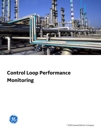
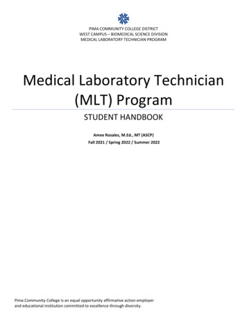
Mechanized Loop Testing MLT OverviewInsulation Test (ALIT) Analyzes problems in CO, outside plant and CPE Can perform rapid and interactive tests Provides VER Codes to permit automated screening.1.4.TEST PATHS FOR POTS, INTEGRATED ANDUNIVERSAL TESTINGFigure 1 1 is an example of test paths for POTS, Integrated and UniversalTesting.Figure 1 1 Test Paths for POTS, Integrated, and Universal Testingfile:///D Page.htm (3 of 105) [10/15/2002 11:22:51 PM]
Mechanized Loop Testing MLT Overview1.5. MLT architectureApplication Software — Resides in transaction processorOperating System/Database — Loop Maintenance Operating System(LMOS) or equivalentLocal Area Network (LAN) — Connects testers to processorData Communications Network (DCN) — Connects processor to testhardwareTest hardware consists of the following components:oLoop Test System (LTS) — For testing POTSo Pair Gain Test Controller (PGTC) — Provides for universalsystem testingo Directly Connected Test Unit (DCTU) — Replaces the LTS andis integrated into the 5ESS (IMLT)o Test Bus Control Unit (TBCU) — Provides for Integrated testingon 5ESS switcho Metallic Test Access (MTA) — Provides for integrated testing onDMS—100 switcho Digital Line Unit (DLU) — Provides for integrated testing onSiemens (EWSD) switch.1.6.MLT Testing Metallic, Universal, ANDfile:///D Page.htm (4 of 105) [10/15/2002 11:22:51 PM]
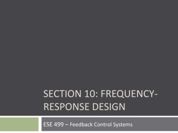
Mechanized Loop Testing MLT OverviewIntegrated SystemsMLT testing for metallic, universal, and integrated systems includes the following: Mechanized Loop Testing Basic Metallic Loop Testing Universal DLC Testing Integrated DLC Testing 5ESS Integrated DLC Testing 5ESS/IMLT (DCTU) Integrated DLC Testing – DMS 100 Integrated DLC Testing – EWSD.1.7.Basic Metallic Loop TestingThe following diagrams are examples of test paths for POTS, integrated, anduniversal testing.Figure 1 2 is an example of Basic Metallic Loop Testing.file:///D Page.htm (5 of 105) [10/15/2002 11:22:51 PM]
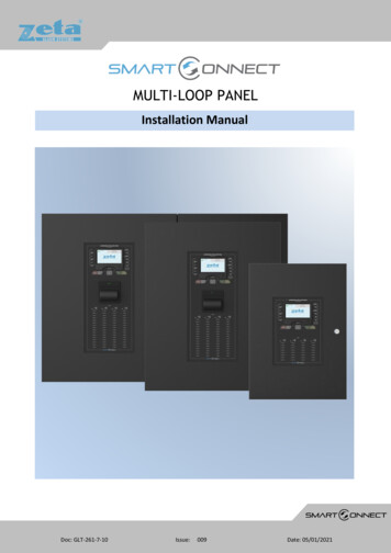
Mechanized Loop Testing MLT OverviewFigure 1 2 Basic Metallic Loop Testing1.8.Universal DLC TestingFigure 1 3 is an example of Universal DLC (UDLC) Testing.file:///D Page.htm (6 of 105) [10/15/2002 11:22:51 PM]
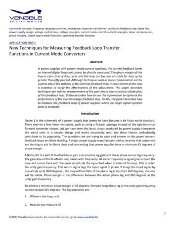
Mechanized Loop Testing MLT OverviewFigure 1 3 Universal DLC Testing1.9.Integrated DLC Testing – 5ESSFigure 1 4 is an example of Integrated DLC Testing for the 5ESS Switch.file:///D Page.htm (7 of 105) [10/15/2002 11:22:51 PM]
Mechanized Loop Testing MLT OverviewFigure 1 4 Integrated DLC Testing 5ESS1.10.Integrated DLC Testing 5ESS/IMLT (DCTU)Figure 1 5 is an example of Integrated DLC Testing for the 5ESS/IMLT (DCTU)Switch.file:///D Page.htm (8 of 105) [10/15/2002 11:22:51 PM]
Mechanized Loop Testing MLT OverviewFigure 1 5 DLC 5ESS/IMLT (DCTU) Testing1.11.Integrated DLC Testing – DMS—100Figure 1 6 is an example of Integrated DLC testing for the DMS—100 Switch.file:///D Page.htm (9 of 105) [10/15/2002 11:22:51 PM]
Mechanized Loop Testing MLT OverviewFigure 1 6 DLC DMS—100 Testing1.12.Integrated DLC Testing – Siemen’s (EWSD)Figure 1 7 is an example of integrated DLC testing for the Siemen’s EWSD.file:///D Page.htm (10 of 105) [10/15/2002 11:22:51 PM]
Mechanized Loop Testing MLT OverviewFigure 1 7 DLC EWSD Testing1.13.MLT System Can Test Plain Old Telephone Service (POTS) Multiparty Coin Private Branch eXchange (PBX) Digital Loop Carrier (DLC) Integrated Services Digital Network (ISDN) Centrex Other circuits, such as alarm systems using MDF test shoe.file:///D Page.htm (11 of 105) [10/15/2002 11:22:51 PM]
Mechanized Loop Testing MLT Overview1.14.MLT – INDIVIDUAL TESTS ANDMEASUREMENTS Hazardous Potential Busy Detection Foreign Electromotive Force (FEMF) Tests Electronic Speech Detection Line in Use Tests – confirmation of busy where no speech is present Receiver Off Hook Detection Intercept Detection Denies Service Detection Direct Current (DC) Tests – an array of configurable DC resistances andvoltagesPBX IdentificationAlternating Current (AC) Signature Identification (An array of configurableAC impedance and voltage) Longitudinal Balance Test Thermistor Test Open Detection and Measurement Line Circuit Test Draw and Break Dial Tone Test. Soak Test Tests to measure variation in DC resistance over time, todetermine if a ground is “swinging” and if it may be “dried out” by applyingvoltage.Ringer Testfile:///D Page.htm (12 of 105) [10/15/2002 11:22:51 PM]
Mechanized Loop Testing MLT Overview Length of Loop Measurement1.15.Questions:1. Name 3 methods to deliver dial tone.2. Identify the 3 main test paths.3. PGTC is used to test what?SECTION 2METALLIC, LTS,AND NTT TESTINGIn This Section:2.1.2-22.2.2-22.3.2-32.4.2-4Lesson Overview.Basic Metallic Loop Testing.Fully Installed LTS Rack.Metallic, LTS, And NTT Testing Architecture.file:///D Page.htm (13 of 105) [10/15/2002 11:22:51 PM]
Mechanized Loop Testing MLT Overview2.1Lesson OverviewLoop Test System (LTS) is a microprocessor—based testhead that tests PlainOld Telephone Service (POTS).It uses digital signal processing to calculate AC and DC equivalent signaturesbased upon three terminal measurements using 150v power amplifiers.It is capable of detecting DC busy loops (with and without speech) by providingtracing tone and interactive tests.No Test Trunks (NTT) reside in the switchand are the means to access subscriberlines.2.2Basic Metallic Loop TestingFigure 1 2 is an example of test paths for POTS testing.file:///D Page.htm (14 of 105) [10/15/2002 11:22:51 PM]
Mechanized Loop Testing MLT OverviewFigure 2 1 Basic Metallic Loop Testing2.3Fully Installed LTS RackFigure 2 2 is an example of a fully installed LTS rack.file:///D Page.htm (15 of 105) [10/15/2002 11:22:51 PM]
Mechanized Loop Testing MLT OverviewFigure 2 2 Fully Installed LTS Rack2.4METALLIC, LTS, AND NTT TESTINGARCHITECTUREFigure 2 3 is an example of the metallic, LTS, and NTT testing architecture.file:///D Page.htm (16 of 105) [10/15/2002 11:22:51 PM]
Mechanized Loop Testing MLT OverviewFigure 2 3 Metallic, LTS, and NTT Testing ArchitectureSECTION 3Universal DLCfile:///D Page.htm (17 of 105) [10/15/2002 11:22:51 PM]
Mechanized Loop Testing MLT OverviewTesting Applications Pair Gain TestController (PGTC)In This Section:3.1.Objective. 323.2.Universal DLC TestingOverview. 3-23.3.Pair Gain Test Controller(PGTC). 3-33.4.PGTC ControlShelf. 3-53.5.PGTCFunctionality. 3-73.6.PGTC CircuitPacks. 3-93.7.PGTC ExpansionShelf. 3-133.8.Exercise: Technical Operation of thePGTC. 3-143.9.PGTC No Test TrunkWiring. 3-163.10.PGTC Lead Wiring To SLCSystems. 3-173.11.PGTC Lead Wiring To DLCSystems. 3-183.12.PGTC 28-Lead Daisy-Chain ControlBus. 3-193.13.Traditional DLC Testing – Metallic By-PassPair. 3-203.14.Tollgrade Method – Digital By-PassPair. 3-213.15.Tip Ring And Inhibit OriginationPoint. 3-22file:///D Page.htm (18 of 105) [10/15/2002 11:22:51 PM]
Mechanized Loop Testing MLT Overview3.16.SLC 96 RT – Wiring For DC TestPair. 3-233.17.Questions. 3243.1.ObjectivesThe student will be able to understand the operation and function of the PGTC,and be able to resolve MLT testing problems in the Universal Digital Loop Carrierarchitecture.3.2.Universal DLC Testing OverviewWithout some assistance, MLT cannot test Universal Digital Loop Carrier lines.The main function of the Pair Gain Test Controller (PGTC) is to provide access touniversal digital carrier lines so that MLT can test. PGTC has to be used,because the Channel Units do not provide a metallic path between the COT andRT.Figure 3 1 is an example of Universal DLC (UDLC) Testing:file:///D Page.htm (19 of 105) [10/15/2002 11:22:51 PM]
Mechanized Loop Testing MLT OverviewFigure 3 1 Universal DLC Testing using a PGTC3.3.PAIR GAIN TEST CONTROLLER (PGTC)The main test hardware in a Universal DLC environment: Provides metallic path by cutting-through metallic test pair (or emulatedmetallic test pair using Tollgrade MCU units) from the CO to remoteterminal (RT) Is a small unit mounted in office bay Is wired between test system LTS and No Test Trunks (NTT) Can assign NTTs to test copper, Universal or Integrated SLC.Figure 3 2 is an example of a Universal DLC MLT Screen.file:///D Page.htm (20 of 105) [10/15/2002 11:22:51 PM]
Mechanized Loop Testing MLT OverviewFigure 3 2 Universal DLC LoopCare ScreenTo determine if you are testing Universal or IntegratedSLC, run a “Quick Test”. If Universal, you should seethe following signature.T – R 3500T – G 165 KohmsR – G 3500file:///D Page.htm (21 of 105) [10/15/2002 11:22:51 PM]
Mechanized Loop Testing MLT OverviewNOTE: Universal DLC testing requires:1.PGTC2.NTT wired into PGTC3.28-pin daisy-chain through all UniversalDLC systems within the COWorking CTU * at CO4.5.Working CTU at RT6.Working CU ** at RT.* Channel Test Unit** Channel Unit3.4.PGTC Control Shelf The control shelf is eight inches (8”) high and is designed to fit intostandard 23” framework. The control shelf requires –48 Vdc (signal grade) at 2.5 amperes(maximum) and uninterrupted ringing voltages wired to pin 10 of the PGTCat 0.5 amperes (maximum). Ringing should be 86 –100 Vac 20 Hz withsuperimposed –42.5 to –52.5 Vdc. Control shelf accommodates up to 12 No Test Trunks (NTT) – 2 trunks per94C card.3.5.PGTC CONTROL SHELFfile:///D Page.htm (22 of 105) [10/15/2002 11:22:51 PM]
Mechanized Loop Testing MLT OverviewFigure 3 3 is an example of PGTC Control Shelf.Figure 3 3 PGTC Control Shelf3.6.PGTC CONTROL SHELFFigure 3 4 is an example of PGTC Control Shelf.Figure 3 4 PGTC Control Shelf Diagramfile:///D Page.htm (23 of 105) [10/15/2002 11:22:51 PM]
Mechanized Loop Testing MLT Overview3.7.SEQUENCEWhen a PGTC needs to run a test, it picks Tester “A” first EVERY TIME. If “A” is busy, it goes to Tester “B”.If “A” and “B” are busy, it goes to Tester “C”. If “A” and “B” and “C” are busy, it goes to Tester “D”.NOTE: The maximum number of Universal DLC teststhat can be run in any office at one time is four (4).3.8.PGTC FunctionalityNOTE: The following conditions will exist if accessline is idle, and LMOS lists subscriber as being onDLC system.1. 116v placed on Tip side of line to wake up DLC channel unit.2.Not seen as a coin disposal potential since ringside isn’t grounded.3. Channel unit activates PGTC and orders Channel Test Units (CTUs) tocut to Metallic Test Path (MTP) through drop.4.After cut-through, screener can perform detailed loop tests:oMetallic testingoRinger countoApplication of trace tone.file:///D Page.htm (24 of 105) [10/15/2002 11:22:51 PM]
Mechanized Loop Testing MLT Overview If MLT sees a valid DLC signature upon access, it will initiate Pair GainTesting Access (with or without live records). The MTP can be shared by up to 10 banks on the same RT site.Banks have Tip (T), Ring (R), and Inhibit (I) leads multiplied at the block onthe same Distributing Frame (DF). T and R are also multiplied at the RT banks.T and R are the actual MTP and the ‘I’ lead prohibits access by more than one CTU at a time.All SLC 96 and Feature Package A (FPA) and FPB Series-5 SLC COT bank CTUs are tied to the PGTC with a 28-lead “daisy-chain” control buslocated at the top of the COT bays. The PGTC can access any CTU and associated MTP.The PGTC also performs an auto test of the T1 channel from the COT to the RT. Results are sent to the tester and can be seen in a displaywindow in the PGTC. Tests include:oGood signal party channeloGood multi-party channeloGood coin channeloBad carrier channel.NOTE: With a 5ESS switch, all plug-ins must meetspecific vintage requirements (as represented in thefollowing sections).3.9.PGTC CIRCUIT PACKSfile:///D Page.htm (25 of 105) [10/15/2002 11:22:51 PM]
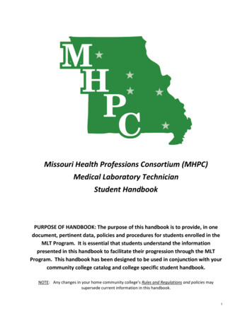
Mechanized Loop Testing MLT Overview3.9.1.SM86 POWER PACKSlot 1 of the control shelf contains an SM86 Power Unit. This required circuitpack provides power for the other circuit packs and control signals within thecontrol shelf. Test jacks are provided on the face of the SM86 for themeasurement of input and output voltages Figure 3 5 page 3 9 shows themeasurement requirements for turning up the control shelf. An alarm lamp isalso located on the front to indicate trouble within the PGTC.Figure 3 5 and diagram shows examples of the PGTC SM86 Power Pack. The first slotcontains an SM86circuit pack,providing power forthe other packs andcontrol signalwithin the shelf. The SM86requires a 48 Vdcsignal grade inputto generate outputsof 5, 12, 48, 48, 130 and 130 Vdc.The 48 Vdc is afiltered talk-gradebattery supply. Test jacks areprovided on theface of the pack formeasurement ofinput and outputvoltages.file:///D Page.htm (26 of 105) [10/15/2002 11:22:51 PM]
Mechanized Loop Testing MLT OverviewFigure 3 5 SM86 Power PackNOTE: SM86 boards should have a current “B” AlphaDesignation.3.9.2.SM87 TESTER UNITSFigure 3 6 is an example of PGTC SM87 Tester Unit. Slots 2, 3, 4 and 5 contain the SM87Tester Units which are referred to as the A,B, C, and D Tester Units. (See Figure 3 3on page 3 5, and Figure 3 4 on page 3 6) Each Unit provides the circuitrynecessary for performing the automatictesting of the channel. Initial testing will attempt to selectTester A. If that unit is busy, the testrequest proceeds to Tester B, etc.Figure 3 6 SM87 Tester Unitsfile:///D Page.htm (27 of 105) [10/15/2002 11:22:51 PM]
Mechanized Loop Testing MLT OverviewNOTE: SM87 boards should have a current “C” AlphaDesignation, series 3 or later.3.9.3.SM88 Control UnitsFigure 3 7 is an example of PGTC SM88 Control Units. Slot 6 contains the SM88 Control Unit,which provides the common controlcircuitry for the PGTC. (See Figure 3 3 onpage 3 5, and Figure 3 4 on page 3 6) The common control circuitry is in theform of a micro-controller package andassociated interface circuitry. Within the micro-controller is aprogram that directs the operation of thecontrol unit.Figure 3 7 SM88 Control Unitsfile:///D Page.htm (28 of 105) [10/15/2002 11:22:51 PM]
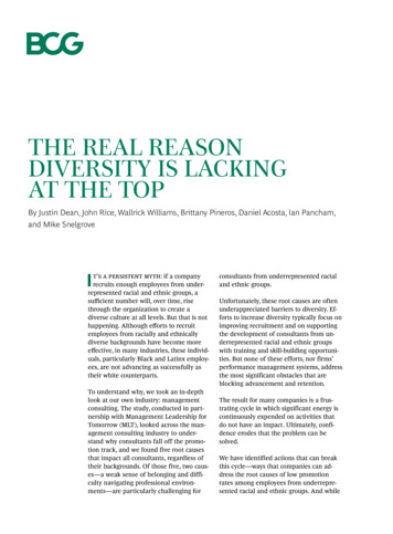
Mechanized Loop Testing MLT OverviewNOTE: SM88 boards should have a current “D” or “C”Alpha Designation. SM88 boards should utilize Series 3or later in “C” cards.3.9.4.SM94C TRUNK UNITSFigure 3 8 is an example of PGTC SM94C Trunk Units. Installed into slots 7 through 12, the SM94CTrunk Units provide a means of connecting anytwo test trunks to any of the available fourtester units. This set-up is referred to asrandom access. (See Figure 3 3 on page 3 5,and Figure 3 4 on page 3 6) The Control Unit allows the Trunk Units tointeract with an available Tester Unit to permitthe NO TEST TRUNK to be switched from theswitching system to the subscriber’s loop.Figure 3 8 SM 94C Trunk Unitsfile:///D Page.htm (29 of 105) [10/15/2002 11:22:51 PM]
Mechanized Loop Testing MLT OverviewNOTE: SM94 boards should have a current “C” AlphaDesignation. SM94 boards should utilize Series 4 orlater in “C” cards.3.10.PGTC EXPANSION SHELFWhen there is a requirement to wire more than 12 NTTs to the PGTC, anexpansion shelf is needed. (The following graphic shows the Expansion Shelfconfiguration) The Expansion Shelf unit is connected to the control shelf and has its ownpower supply The Expansion Shelf must be physically located just below the Control Shelf The Expansion Shelf has its own power supply and supports up to 20additional trunks (2 trunks per 94C card) A maximum of 4 Expansion Shelfs may be installed.Figure 3 9 is an example of PGTC Expansion Shelf.Figure 3 9 PGTC Expansion Shelffile:///D Page.htm (30 of 105) [10/15/2002 11:22:51 PM]
Mechanized Loop Testing MLT Overview3.11.Exercise: Technical Operation of the PGTCFigure 3 10 is an example of PGTC Technical Operation:Figure 3 10 PGTC Technical OperationThe technical operation of the PGTC is described in the following steps:Table 1 Technical Operation of the PGTCSTEP1.2.DESCRIPTIONWhen 116 Vdc or a minimum of 87 Vdc is applied fromMLT to the Tip side of the circuit, the COT channel unitapplies a 333.3Hz tone to the T and R leads back to thePGTC.At the PGTC, a tone detector in the SM94 Trunk Unitdetects the tone and presents information to the SM88Control Unit. Additionally, a GREEN busy lamp will lighton the SM94 Trunk Unit.file:///D Page.htm (31 of 105) [10/15/2002 11:22:51 PM]
Mechanized Loop Testing MLT Overview3.An NSeize command is output from the COT channel unitto the COT CTU and over the digital line to the RTchannel unit.4.An NSeize command is output from the RT channel unit tothe RT CTU and over the digital line to the COT channelunit.5.The COT CTU outputs a Seize command to the PGTCSM88 Control Unit.6.The SM88 Control Unit selects an available A through DTester Unit and runs internal tests.7.The PGTC sends a PROCEED command to the COTCTU which is transmitted to the RT CTU via the DLUs.8.The RT CTU will issue an NGATE command to all RTchannel units.9.The channel unit at the RT that previously received theNSeize command will connect its Tip and Ring to the CTUby operating a relay within the channel unit.10.A busy lamp lights on the COT and RT channel units.11.The COT CTU outputs a SLEEVE command to the SM88Control Unit.12.The SM88 Control Unit outputs a LOCK command to theCTU.13.The SM88 Control Unit removes the ground placed earlierduring the PROCEED step.file:///D Page.htm (32 of 105) [10/15/2002 11:22:51 PM]
Mechanized Loop Testing MLT Overview14.The PGTC places a 1KOhm resistance on the Tip leadtowards MLT to indicate that a test connection isestablished.At this point, the MLT test will be completed normally. A by-pass of theelectronics is effectively completed.3.12.PGTC No Test Trunk WiringFigure 3 11 is an example of PGTC No Test Trunk Wiring.Figure 3 11 PGTC No Test Trunk Wiring3.13. From the PGTC to each system, a continuous 25 pair cable, containing the28-leads, is chained through Amphenol plugs to each SLC system. Eachof the 4 PGTC Tester Units (A, B, C, D) have: PGTC LEAD WIRING TO SLC SYSTEMSTip6 leads from the PGTC unit to the SLC systems. OH LOKfile:///D Page.htm (33 of 105) [10/15/2002 11:22:52 PM]
Mechanized Loop Testing MLT Overview Ring PROC SLV4 common leads connecting the PGTC to the SLC systems.ALM (orTSTALM) SEIZE SEIZE-BY TMAJ3.14.PGTC LEAD WIRING TO DLC SYSTEMSTable 2 PGTC Lead Wiring to DLC Systemsfile:///D Page.htm (34 of 105) [10/15/2002 11:22:52 PM]
Mechanized Loop Testing MLT Overview3.15.BUSPGTC 28-LEAD DAISY-CHAIN CONTROLFigure 3 12 is an example of the PGTC 28 Lead daisy chain control bus.file:///D Page.htm (35 of 105) [10/15/2002 11:22:52 PM]
Mechanized Loop Testing MLT OverviewFigure 3 12 PGTC 28-Lead Daisy-Chain Control Bus3.16.TRADITIONAL DLC TESTING – METALLICBY-PASS PAIRDescription: Copper DC Test Pair Architecture.Figure 3 13 represents the Traditional DLC Testing Metallic By Pass Pairarchitecture.file:///D Page.htm (36 of 105) [10/15/2002 11:22:52 PM]
Mechanized Loop Testing MLT OverviewFigure 3 13 Traditional DLC Testing - Metallic By-Pass Pair3.17.PAIRTOLLGRADE METHOD – DIGITAL BY-PASSDescription: MCU Technology Architecture.Figure 3 14 represents the MCU technology architecture.file:///D Page.htm (37 of 105) [10/15/2002 11:22:52 PM]
Mechanized Loop Testing MLT OverviewFigure 3 14 Tollgrade Method - Digital By-Pass Pair3.18.TIP RING and INHIBIT ORIGINATION POINTTable 3 is an example of the Tip, Ring, and Inhibit Origination Point architecture.Table 3 Tip, Ring, and Inhibit Origination Point.SLC 96SLC SERIES 5CTU PIN OUTFUJITSUFDLCCTUPINOUTDSCLITESPAN-2000A BLUE B WHITETRM 1TB8 JIfile:///D Page.htm (38 of 105) [10/15/2002 11:22:52 PM]
Mechanized Loop Testing MLT OverviewSLC 96 RT – Wiring for DC test pair – Provides the metallic path from the CO toand-through the remote tunnel. DC test pair for MCU tip and ring is wired to theJ107 Pair 5 and then internally to the SLC 96 Systems 1, 2, 3, etc. (For furtherinformation see PTAP Reference Documents Section 2 Error! Referencesource not found. page Error! Bookmark not defined.)Figure 3 15 is an example of the SLC 96 RT – Wiring for DC test pair.Figure 3 15 SLC 96 RT – Wiring for DC Test Pairfile:///D Page.htm (45 of 105) [10/15/2002 11:22:52 PM]
Mechanized Loop Testing MLT OverviewT TipR RingWhen CTUs/MCUs are busy,you will see:I INHIBITAt the Central Office:VoltageMeasuredtoGroundT 0R 0I GNDAt the RT:T 0ATTENTION!R 0When CTUs/MCUs are idle,you will see:At the Central Office:T 0R -48VI -48VAt the RT:T 0R -48Vfile:///D Page.htm (46 of 105) [10/15/2002 11:22:52 PM]
Mechanized Loop Testing MLT OverviewNOTE: Inhibit lead wiring is necessary becauseanother test could come in over top. You need toremove battery from R. If you don’t, you will see across to a working pair (referred to as a false test).1.16.QUESTIONS1. What is the main function of the PGTC?SECTION 4Integrated DLCTesting ApplicationsIn This Section:4.1.24.2.24.3.34.4.44.5.5Objectives. 4Lesson Overview. 4Integrated DLC Testing - 5ESS TBCU Overview. 4DMS-100 – IDLC Testing Overview. 4DMS-100 – UDLC/IDLC Testing Architecture. 4-file:///D Page.htm (47 of 105) [10/15/2002 11:22:52 PM]
Mechanized Loop Testing MLT Overview4.6.64.7.74.8.84.1.Siemen’s (EWSD) Testing Overview. 4Quick Test of an Integrated DLC Line. 4Questions. 4-ObjectivesThe student will understand the MLT testing paths for integrated digital loopcarrier testing.4.2.Lesson OverviewThis lesson will introduce the most important Integrated DLC Testing Application,and how they are utilized.The following are examples of the Integrated DLC Testing Applications: 5ESS – TBCU DMS-100 – IDLC TESTINGfile:///D Page.htm (48 of 105) [10/15/2002 11:22:52 PM]
Mechanized Loop Testing MLT Overview Siemens’ (EWSD) DLU.4.3.INTEGRATED DLC TESTING - 5ESS TBCUoverview For Integrated DLC testing in a 5ESS, the Test Bus Control Unit (TBCU)performs the IDLC test function. If a 5ESS is equipped with both Universal and Integrated DLC, both thePGTC and the TBCU are required. The TBCU replaces the PGTC only with IDLC.Figure 4 1 is an example of the Integrated DLC Testing - 5ESS.file:///D Page.htm (49 of 105) [10/15/2002 11:22:52 PM]
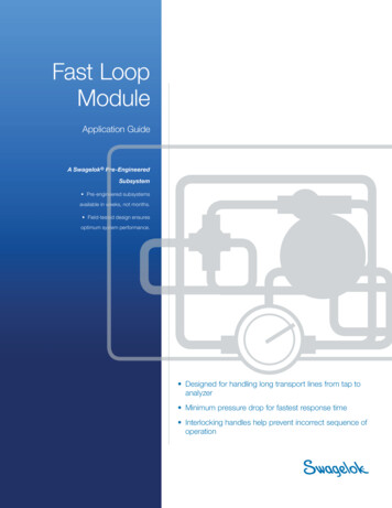
Mechanized Loop Testing MLT OverviewFigure 4 1 Integrated DLC Testing - 5ESS4.4. DMS-100 – IDLC Testing OverviewThe DMS Switch also has IDLC capability. It uses a Metallic Test Access (MTA) circuit (similar to the MSU),Subscriber Multiplexer SLC 96 (SMS) interfaces (similar to DCLUs or IDCUs),and Pair Gain Applique (similar to the TBCU).Figure 4 2 is an example of the DMS-100 – IDLC Testing Architecture.Figure 4 2 DMS-100 – IDLC Testing Architecturefile:///D Page.htm (50 of 105) [10/15/2002 11:22:52 PM]
Mechanized Loop Testing MLT Overview4.5.DMS-100 – UDLC/IDLC Testing ArchitectureFigure 4 3 is an example of the DMS-100 – UDLC and IDLC TestingArchitecture.Figure 4 3 DMS-100 – UDLC and IDLC Testing Architecture4.6.Siemen’s (EWSD) Testing Overviewfile:///D Page.htm (51 of 105) [10/15/2002 11:22:52 PM]
Mechanized Loop Testing MLT Overview
is integrated into the 5ESS (IMLT) o Test Bus Control Unit (TBCU) — Provides for Integrated testing on 5ESS switch o Metallic Test Access (MTA) — Provides for integrated testing on DMS—100 switch o Digital Line Unit (DLU) — Provides for integrated testing on Siemens (EWSD) switch. 1.6. MLT Testing Metallic, Universal, AND