Transcription
DATA SHEETwww.onsemi.com1.0 A Low-Dropout PositiveFixed and AdjustableVoltage RegulatorsNCP1117, NCP1117I,NCV1117PIN CONFIGURATIONTabThe NCP1117 series are low dropout positive voltage regulators thatare capable of providing an output current that is in excess of 1.0 Awith a maximum dropout voltage of 1.2 V at 800 mA overtemperature. This series contains nine fixed output voltages of 1.5 V,1.8 V, 1.9 V, 2.0 V, 2.5 V, 2.85 V, 3.3 V, 5.0 V, and 12 V that have nominimum load requirement to maintain regulation. Also included is anadjustable output version that can be programmed from 1.25 V to18.8 V with two external resistors. On chip trimming adjusts thereference/output voltage to within 1.0% accuracy. Internal protectionfeatures consist of output current limiting, safe operating areacompensation, and thermal shutdown. The NCP1117 series canoperate with up to 20 V input. Devices are available in SOT 223 andDPAK packages.Features Output Current in Excess of 1.0 A 1.2 V Maximum Dropout Voltage at 800 mA Over Temperature Fixed Output Voltages of 1.5 V, 1.8 V, 1.9 V, 2.0 V, 2.5 V, 2.85 V, DPAKDT SUFFIXCASE 369CSOT 223ST SUFFIXCASE 318H3.3 V, 5.0 V, and 12 VAdjustable Output Voltage OptionNo Minimum Load Requirement for Fixed Voltage Output DevicesReference/Output Voltage Trimmed to 1.0%Current Limit, Safe Operating and Thermal Shutdown ProtectionOperation to 20 V InputNCV Prefix for Automotive and Other Applications RequiringUnique Site and Control Change Requirements; AEC Q100Qualified and PPAP CapableThese are Pb-Free Devices123SOT 223(Top View)Tab123DPAK(Top View)Pin: 1. Adjust/Ground2. Output3. InputHeatsink tab is connected to Pin 2.ORDERING INFORMATIONSee detailed ordering and shipping information in the packagedimensions section on page 12 of this data sheet.DEVICE MARKING INFORMATIONSee general marking information in the device markingsection on page 14 of this data sheet.Applications Consumer and Industrial Equipment Point of RegulationActive SCSI Termination for 2.85 V VersionSwitching Power Supply Post RegulationHard Drive ControllersBattery Chargers Semiconductor Components Industries, LLC, 2017August, 2021 Rev. 311Publication Order Number:NCP1117/D
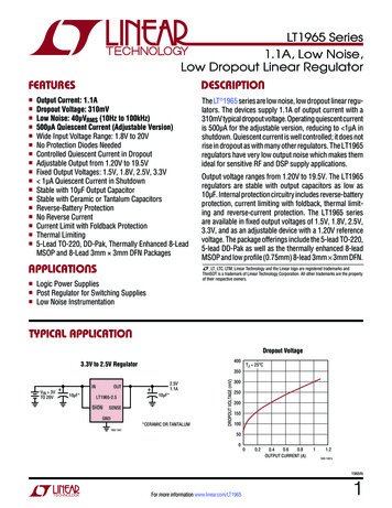
NCP1117, NCP1117I, NCV1117TYPICAL APPLICATIONS110 WInput10mF3 NCP1117XTXX2 Output1Input310mF 10mFNCP1117XTA132 Output10mF 10mF4.75 Vto5.25 VFigure 1. FixedOutput RegulatorFigure 2. AdjustableOutput Regulator NCP1117XT285110 W2 221mF 110 W18 to 27Lines110 WFigure 3. Active SCSI Bus TerminatorMAXIMUM RATINGSRatingSymbolValueUnitVin20V Infinite PDRqJARqJCInternally Limited16015W C/W C/WPDRqJARqJCInternally Limited676.0W C/W C/WMaximum Die Junction Temperature RangeTJ 55 to 150 CStorage Temperature RangeTstg 65 to 150 COperating Ambient Temperature RangeNCP1117NCP1117INCV1117TAInput Voltage (Note 1)Output Short Circuit Duration (Notes 2 and 3)Power Dissipation and Thermal CharacteristicsCase 318H (SOT 223)Power Dissipation (Note 2)Thermal Resistance, Junction to Ambient, Minimum Size PadThermal Resistance, Junction to CaseCase 369A (DPAK)Power Dissipation (Note 2)Thermal Resistance, Junction to Ambient, Minimum Size PadThermal Resistance, Junction to Case0 to 125 40 to 125 40 to 125 CStresses exceeding those listed in the Maximum Ratings table may damage the device. If any of these limits are exceeded, device functionalityshould not be assumed, damage may occur and reliability may be affected.1. This device series contains ESD protection and exceeds the following tests:Human Body Model (HBM), Class 2, 2000 VMachine Model (MM), Class B, 200 VCharge Device Model (CDM), Class IV, 2000 V.2. Internal thermal shutdown protection limits the die temperature to approximately 175 C. Proper heatsinking is required to prevent activation.The maximum package power dissipation is:TJ(max) * TAPD RqJA3. The regulator output current must not exceed 1.0 A with Vin greater than 12 V.www.onsemi.com2
NCP1117, NCP1117I, NCV1117ELECTRICAL CHARACTERISTICS(Cin 10 mF, Cout 10 mF, for typical value TA 25 C, for min and max values TA is the operating ambient temperature range that appliesunless otherwise noted.) (Note 4)CharacteristicSymbolReference Voltage, Adjustable Output Devices(Vin–Vout 2.0 V, Iout 10 mA, TA 25 C)(Vin–Vout 1.4 V to 10 V, Iout 10 mA to 800 mA) (Note 4)VrefOutput Voltage, Fixed Output Devices1.5 V (Vin 3.5 V, Iout 10 mA, TA 25 C)(Vin 2.9 V to 11.5 V, Iout 0 mA to 800 mA) (Note 4)VoutMinTypMax1.2381.2251.25 1.2621.2701.4851.4701.500 1.5151.530UnitVV1.8 V(Vin 3.8 V, Iout 10 mA, TA 25 C)(Vin 3.2 V to 11.8 V, Iout 0 mA to 800 mA) (Note 4)1.7821.7551.800 1.8181.8451.9 V(Vin 3.9 V, Iout 10 mA, TA 25 C)(Vin 3.3 V to 11.9 V, Iout 0 mA to 800 mA) (Note 4)1.8721.8621.9001.9001.9291.9382.0 V(Vin 4.0 V, Iout 10 mA, TA 25 C)(Vin 3.4 V to 12 V, Iout 0 mA to 800 mA) (Note 4)1.9701.9602.000 2.0302.0402.5 V(Vin 4.5 V, Iout 10 mA, TA 25 C)(Vin 3.9 V to 10 V, Iout 0 mA to 800 mA,) (Note 4)2.4752.4502.500 2.5252.5502.85 V (Vin 4.85 V, Iout 10 mA, TA 25 C)(Vin 4.25 V to 10 V, Iout 0 mA to 800 mA) (Note 4)(Vin 4.0 V, Iout 0 mA to 500 mA) (Note 4)2.8212.7902.7902.850 2.8792.9102.9103.3 V(Vin 5.3 V, Iout 10 mA, TA 25 C)(Vin 4.75 V to 10 V, Iout 0 mA to 800 mA) (Note 4)3.2673.2353.300 3.3333.3655.0 V(Vin 7.0 V, Iout 10 mA, TA 25 C)(Vin 6.5 V to 12 V, Iout 0 mA to 800 mA) (Note 4)4.9504.9005.000 5.0505.10012 V(Vin 14 V, Iout 10 mA, TA 25 C)(Vin 13.5 V to 20 V, Iout 0 mA to 800 mA) (Note 4)11.88011.76012.000 12.12012.240 0.040.1% 07.5mV 0.20.4% mV 0.951.011.071.101.151.20Iout100015002200mAIL(min) 0.85.0mALine Regulation (Note 5)1.5 V1.8 V1.9 V2.0 V2.5 V2.85 V3.3 V5.0 V12 VLoad Regulation (Note 5)1.5 V1.8 V1.9 V2.0 V2.5 V2.85 V3.3 V5.0 V12 VAdjustable (Vin 2.75 V to 16.25 V, Iout 10 mA)Regline(Vin 2.9 V to 11.5 V, Iout 0 mA)(Vin 3.2 V to 11.8 V, Iout 0 mA)(Vin 3.3 V to 11.9 V, Iout 0 mA)(Vin 3.4 V to 12 V, Iout 0 mA)(Vin 3.9 V to 10 V, Iout 0 mA)(Vin 4.25 V to 10 V, Iout 0 mA)(Vin 4.75 V to 15 V, Iout 0 mA)(Vin 6.5 V to 15 V, Iout 0 mA)(Vin 13.5 V to 20 V, Iout 0 mA)Adjustable (Iout 10 mA to 800 mA, Vin 4.25 V)Regline(Iout 0 mA to 800 mA, Vin 2.9 V)(Iout 0 mA to 800 mA, Vin 3.2 V)(Iout 0 mA to 800 mA, Vin 3.3 V)(Iout 0 mA to 800 mA, Vin 3.4 V)(Iout 0 mA to 800 mA, Vin 3.9 V)(Iout 0 mA to 800 mA, Vin 4.25 V)(Iout 0 mA to 800 mA, Vin 4.75 V)(Iout 0 mA to 800 mA, Vin 6.5 V)(Iout 0 mA to 800 mA, Vin 13.5 V)Dropout Voltage (Measured at Vout 100 mV)(Iout 100 mA)(Iout 500 mA)(Iout 800 mA)Vin VoutOutput Current Limit (Vin Vout 5.0 V, TA 25 C, Note 6)Minimum Required Load Current for Regulation, Adjustable Output Devices(Vin 15 V)www.onsemi.com3V
NCP1117, NCP1117I, NCV1117ELECTRICAL CHARACTERISTICS (continued)(Cin 10 mF, Cout 10 mF, for typical value TA 25 C, for min and max values TA is the operating ambient temperature range that appliesunless otherwise noted.) (Note 4)CharacteristicSymbolQuiescent Current1.5 V (Vin 11.5 V)1.8 V (Vin 11.8 V)1.9 V (Vin 11.9 V)2.0 V (Vin 12 V)2.5 V (Vin 10 V)2.85 V (Vin 10 V)3.3 V (Vin 15 V)5.0 V (Vin 15 V)12 V (Vin 20 V)IQThermal Regulation (TA 25 C, 30 ms Pulse)MinTypMax 3.64.24.34.55.25.56.06.06.0101010101010101010 0.010.16766666664626260575073727072706868646154 UnitmA%/WRipple Rejection (Vin Vout 6.4 V, Iout 500 mA, 10 Vpp 120 Hz Sinewave)Adjustable1.5 V1.8 V1.9 V2.0 V2.5 V2.85 V3.3 V5.0 V12 VRRAdjustment Pin Current (Vin 11.25 V, Iout 800 mA)Iadj 52120mADIadj 0.45.0mATemperature StabilityST 0.5 %Long Term Stability (TA 25 C, 1000 Hrs End Point Measurement)St 0.3 %RMS Output Noise (f 10 Hz to 10 kHz)N 0.003 %VoutAdjust Pin Current Change(Vin Vout 1.4 V to 10 V, Iout 10 mA to 800 mA)dBProduct parametric performance is indicated in the Electrical Characteristics for the listed test conditions, unless otherwise noted. Productperformance may not be indicated by the Electrical Characteristics if operated under different conditions.Thigh 125 C4. NCP1117: Tlow 0 C,NCP1117I: Tlow 40 C, Thigh 125 CNCV1117: Tlow 40 C, Thigh 125 C5. Low duty cycle pulse techniques are used during testing to maintain the junction temperature as close to ambient as possible.6. The regulator output current must not exceed 1.0 A with Vin greater than 12 V.www.onsemi.com4
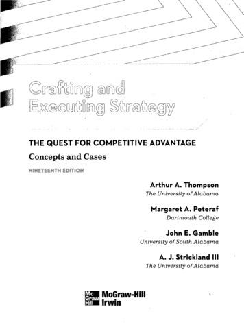
2.01.4Vin Vout 3.0 VIout 10 mA1.5Vin Vout, DROPOUT VOLTAGE (V)Vout, OUTPUT VOLTAGE CHANGE (%)NCP1117, NCP1117I, NCV1117Adj, 1.5 V,1.8 V, 2.0 V,2.5 V1.00.50 0.52.85 V, 3.3 V,5.0 V, 12.0 V 1.0 1.5 2.0 50 2502550751000.2Load pulsed at 1.0% duty cycle02004006008001.00.5468101214161810002.0Iout, OUTPUT CURRENT (A)Iout, OUTPUT CURRENT (A)0.4Figure 5. Dropout Voltagevs. Output CurrentLoad pulsed at 1.0% duty cycle1.81.61.41.21.0 5020Vin 5.0 VLoad pulsed at 1.0% duty cycle 250255075100125Vin Vout, VOLTAGE DIFFERENTIAL (V)TA, AMBIENT TEMPERATURE ( C)Figure 6. Output Short Circuit Currentvs. Differential VoltageFigure 7. Output Short Circuit Currentvs. TemperatureIQ, QUIESCENT CURRENT CHANGE (%)100Iadj, ADJUST PIN CURRENT (mA)0.6Figure 4. Output Voltage Changevs. Temperature1.52TJ 125 CIout, OUTPUT CURRENT (mA)TJ 25 C00.8TA, AMBIENT TEMPERATURE ( C)2.00TJ 40 C1.00150125TJ 25 C1.28060150105.00 5.040200 50Iout 10 mA 250255075100125150 10 15 20 50 250255075100125TA, AMBIENT TEMPERATURE ( C)TA, AMBIENT TEMPERATURE ( C)Figure 8. Adjust Pin Currentvs. TemperatureFigure 9. Quiescent Current Changevs. Temperaturewww.onsemi.com5150
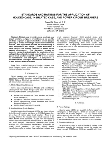
NCP1117, NCP1117I, NCV11171008060fripple 20 kHzVripple v 0.5 VP P40Vout 5.0 VVin Vout 3.0 VCout 10 mFCadj 25 mFTA 25 C200RR, RIPPLE REJECTION (dB)fripple 120 HzVripple v 3.0 VP P020040060080060Vout 5.0 VVin Vout 3.0 VIout 0.5 ACout 10 mFCadj 25 mF, f 60 HzCadj 200 mF, f v 60 HzTA 25 C402010100Vin Vout w Vdropout1.0 k10 kFigure 10. NCP1117XTA Ripple Rejectionvs. Output CurrentFigure 11. NCP1117XTA Ripple Rejectionvs. FrequencyVin 3.0 VVout 1.25 VIload 5 mA 1 ACin 10 mF MLCCTJ 25 C10Region of Instability0.010.1110Region of Stability10.010Region of Instability100 200 300 400 500 600 700 800 900 1000Iout, OUTPUT CURRENT (mA)Figure 13. Typical ESR vs. Output Current350E 91ACin 10 mF TantalumCout 10 mF TantalumVin Vout 3.0 V0.5 A250E 9200E 90.1 A150E 9100E 950E 9010100Vin 3.0 VVout 1.25 VCin 10 mF MLCCCout 10 mFTJ 25 C0.1Figure 12. Output Capacitance vs. ESR300E 9100 k10ESR, EQUIVALENT SERIES RESISTANCE (W)V/sqrt (Hz)OUTPUT CAPACITANCE (mF)Vin Vout w 3.0 Vfripple, RIPPLE FREQUENCY (Hz)Region of Stability0.10.001Vripple v 0.5 VP PIout, OUTPUT CURRENT (mA)1001Vripple v 3.0 VP P8001000ESR, EQUIVALENT SERIES RESISTANCE (W)RR, RIPPLE REJECTION (dB)1001.0 k10 k100 kFREQUENCY (Hz)Figure 14. Output Spectral Noise Density vs.Frequency, Vout 1V5www.onsemi.com6
5.250200 2040801200.50200160Cin 10 mFCout 10 mFVin 4.5 VPreload 0.1 ATA 25 C 0.1040Figure 16. NCP1117XT285Load Transient Response7.5200 20801200Cin 10 mFCout 10 mFVin 6.5 VPreload 0.1 ATA 25 C0.5020016004080120OUTPUT VOLTAGEDEVIATION (V)0.10Cin 10 mFCout 10 mFVin 13.5 VPreload 0.1 ATA 25 C 0.1LOAD CURRENTCHANGE (A)13.5200 204080120200Figure 18. NCP1117XT50Load Transient ResponseCin 1.0 mFCout 10 mFIout 0.1 ATA 25 C0160t, TIME (ms)Figure 17. NCP1117XT50Line Transient Response14.52000.1 0.16.540160Figure 15. NCP1117XT285Line Transient Responset, TIME (ms)INPUTVOLTAGE (V)120t, TIME (ms)Cin 1.0 mFCout 10 mFIout 0.1 ATA 25 C0OUTPUT VOLTAGEDEVIATION (mV)80t, TIME (ms)LOAD CURRENTCHANGE (A)INPUTVOLTAGE (V)0.1LOAD CURRENTCHANGE (A)4.250OUTPUT VOLTAGEDEVIATION (mV)OUTPUT VOLTAGEDEVIATION (V)Cin 1.0 mFCout 10 mFIout 0.1 ATA 25 COUTPUT VOLTAGEDEVIATION (V)OUTPUT VOLTAGEDEVIATION (mV)INPUTVOLTAGE (V)NCP1117, NCP1117I, NCV11171600.50200t, TIME (ms)04080120160t, TIME (ms)Figure 20. NCP1117XT12 LoadTransient ResponseFigure 19. NCP1117XT12 LineTransient Responsewww.onsemi.com7200
RqJA, THERMAL RESISTANCE,JUNCTION TO AIR ( CW)1801.61601.4PD(max) for TA 50 C140ÎÎÎÎÎÎÎÎÎ2.0 oz. CopperLMinimumSize Pad120L1008060RqJA05.010152025L, LENGTH OF COPPER (mm)1.21.00.80.60.430PD, MAXIMUM POWER DISSIPATION (W)NCP1117, NCP1117I, NCV1117RqJA, THERMAL RESISTANCE,JUNCTION TO AIR ( CW)1001.6PD(max) for TA 50 C1.490ÎÎÎÎÎÎÎÎÎÎÎÎÎÎÎÎ2.0 oz. CopperL80MinimumSize Pad701.0L0.860500.6RqJA401.205.0101520250.430L, LENGTH OF COPPER (mm)Figure 22. DPAK Thermal Resistance and MaximumPower Dissipation vs. P.C.B. Copper Lengthwww.onsemi.com8PD, MAXIMUM POWER DISSIPATION (W)Figure 21. SOT 223 Thermal Resistance and MaximumPower Dissipation vs. P.C.B. Copper Length
NCP1117, NCP1117I, NCV1117APPLICATIONS INFORMATIONIntroductionFrequency compensation for the regulator is provided bycapacitor Cout and its use is mandatory to ensure outputstability. A minimum capacitance value of 4.7 mF with anequivalent series resistance (ESR) that is within the limits of33 mW (typ) to 2.2 W is required. See Figures 12 and 13. Thecapacitor type can be ceramic, tantalum, or aluminumelectrolytic as long as it meets the minimum capacitancevalue and ESR limits over the circuit’s entire operatingtemperature range. Higher values of output capacitance canbe used to enhance loop stability and transient response withthe additional benefit of reducing output noise.The NCP1117 features a significant reduction in dropoutvoltage along with enhanced output voltage accuracy andtemperature stability when compared to older industrystandard three terminal adjustable regulators. Thesedevices contain output current limiting, safe operating areacompensation and thermal shutdown protection makingthem designer friendly for powering numerous consumerand industrial products. The NCP1117 series is pincompatible with the older LM317 and its derivative devicetypes.Output VoltageInputThe typical application circuits for the fixed andadjustable output regulators are shown in Figures 23 and 24.The adjustable devices are floating voltage regulators. Theydevelop and maintain the nominal 1.25 V reference voltagebetween the output and adjust pins. The reference voltage isprogrammed to a constant current source by resistor R1, andthis current flows through R2 to ground to set the outputvoltage. The programmed current level is usually selected tobe greater than the specified 5.0 mA minimum that isrequired for regulation. Since the adjust pin current, Iadj, issignificantly lower and constant with respect to theprogrammed load current, it generates a small outputvoltage error that can usually be ignored. For the fixedoutput devices R1 and R2 are included within the device andthe ground current Ignd, ranges from 3.0 mA to 5.0 mAdepending upon the output voltage.CinCin NCP1117XTXX1 CoutCadjǓVout Vref 1 ) R2 ) Iadj R2R1Figure 24. Adjustable Output RegulatorThe output ripple will increase linearly for fixed andadjustable devices as the ratio of output voltage to thereference voltage increases. For example, with a 12 Vregulator, the output ripple will increase by 12 V/1.25 V or9.6 and the ripple rejection will decrease by 20 log of thisratio or 19.6 dB. The loss of ripple rejection can be restoredto the values shown with the addition of bypass capacitorCadj, shown in Figure 24. The reactance of Cadj at the ripplefrequency must be less than the resistance of R1. The valueof R1 can be selected to provide the minimum required loadcurrent to maintain regulation and is usually in the range of100 W to 200 W.Cadj u12 p fripple R1The minimum required capacitance can be calculatedfrom the above formula. When using the device in anapplication that is powered from the AC line via atransformer and a full wave bridge, the value for Cadj is:Output2R1Vref1ǒOutput2R2Input bypass capacitor Cin may be required for regulatorstability if the device is located more than a few inches fromthe power source. This capacitor will reduce the circuit’ssensitivity when powered from a complex source impedanceand significantly enhance the output transient response. Theinput bypass capacitor should be mounted with the shortestpossible track length directly across the regulator’s inputand ground terminals. A 10 mF ceramic or tantalumcapacitor should be adequate for most applications.3 NCP1117XTAIadjExternal CapacitorsInput3fripple 120 Hz, R1 120 W, then Cadj u 11.1 mFThe value for Cadj is significantly reduced in applicationswhere the input ripple frequency is high. If used as a postregulator in a switching converter under the followingconditions:CoutIgndfripple 50 kHz, R1 120 W, then Cadj u 0.027 mFFigure 23. Fixed Output RegulatorFigures 10 and 11 shows the level of ripple rejection thatis obtainable with the adjust pin properly bypassed.www.onsemi.com9
NCP1117, NCP1117I, NCV1117Protection DiodesThe second condition is that the ground end of R2 should beconnected directly to the load. This allows true Kelvinsensing where the regulator compensates for the voltagedrop caused by wiring resistance RW .The NCP1117 family has two internal low impedancediode paths that normally do not require protection whenused in the typical regulator applications. The first pathconnects between Vout and Vin, and it can withstand a peaksurge current of about 15 A. Normal cycling of Vin cannotgenerate a current surge of this magnitude. Only when Vinis shorted or crowbarred to ground and Cout is greater than50 mF, it becomes possible for device damage to occur.Under these conditions, diode D1 is required to protect thedevice. The second path connects between Cadj and Vout, andit can withstand a peak surge current of about 150 mA.Protection diode D2 is required if the output is shorted orcrowbarred to ground and Cadj is greater than 1.0 mF.InputCinCin RW 2 R11CoutR2OutputRemoteLoadFigure 26. Load SensingThermal Considerations1N40013 NCP1117XTARW D1Input3NCP1117XTA1R2This series contains an internal thermal limiting circuitthat is designed to protect the regulator in the event that themaximum junction temperature is exceeded. Whenactivated, typically at 175 C, the regulator output switchesoff and then back on as the die cools. As a result, if the deviceis continuously operated in an overheated condition, theoutput will appear to be oscillating. This feature providesprotection from a catastrophic device failure due toaccidental overheating. It is not intended to be used as asubstitute for proper heatsinking. The maximum devicepower dissipation can be calculated by:Output2R1 D21N4001 CoutCadjFigure 25. Protection Diode PlacementA combination of protection diodes D1 and D2 may berequired in the event that Vin is shorted to ground and Cadjis greater than 50 mF. The peak current capability stated forthe internal diodes are for a time of 100 ms with a junctiontemperature of 25 C. These values may vary and are to beused as a general guide.PD TJ(max) * TARqJAThe devices are available in surface mount SOT 223 andDPAK packages. Each package has an exposed metal tabthat is specifically designed to reduce the junction to airthermal resistance, RqJA, by utilizing the printed circuitboard copper as a heat dissipater. Figures 21 and 22 showtypical RqJA values that can be obtained from a squarepattern using economical single sided 2.0 ounce copperboard material. The final product thermal limits should betested and quantified in order to insure acceptableperformance and reliability. The actual RqJA can varyconsiderably from the graphs shown. This will be due to anychanges made in the copper aspect ratio of the final layout,adjacent heat sources, and air flow.Load RegulationThe NCP1117 series is capable of providing excellentload regulation; but since these are three terminal devices,only partial remote load sensing is possible. There are twoconditions that must be met to achieve the maximumavailable load regulation performance. The first is that thetop side of programming resistor R1 should be connected asclose to the regulator case as practicable. This will minimizethe voltage drop caused by wiring resistance RW fromappearing in series with reference voltage that is across R1.www.onsemi.com10
NCP1117, NCP1117I, NCV1117InputNCP1117XTA3 10mFConstant CurrentOutputR2 1Input 10mF10mFNCP1117XTA3Output2 R11R250 k2N2907Figure 28. Slow Turn On RegulatorInputInput310mF On Output2R11 101202N2222NCP1117XTA310mFOutput211.0 kOutput ControlNCP1117XTA10mF10mFVIout ref ) IadjRFigure 27. Constant Current Regulator1N4001 10mFR2mF2N22223601.0 kOffOutput Voltage ControlResistor R2 sets the maximum output voltage. Eachtransistor reduces the output voltage when turned on.Vout(Off) VrefFigure 29. Regulator with ShutdownInput310mF NCP1117XT502mF 10mFInput5.3 V AC Line5.0 V Battery3 Output 10150 WRCHG6.6 VFigure 30. Digitally Controlled Regulator NCP1117XT5010mF23 NCP1117XT50mF12.0 k1Output5.0 V to12 V 102 10mFThe 50 W resistor that is in series with the ground pin of theupper regulator level shifts its output 300 mV higher than thelower regulator. This keeps the lower regulator off until theinput source is removed.Figure 31. Battery Backed Up Power SupplyFigure 32. Adjusting Output of FixedVoltage Regulatorswww.onsemi.com11
NCP1117, NCP1117I, NCV1117ORDERING INFORMATION (NCP1117)DeviceNominal Output ckageShipping†SOT 223(Pb Free)4000 / Tape & ReelNCP1117DTAGAdjustable75 Units / RailNCP1117DTARKGAdjustable2500 / Tape & ReelNCP1117DTAT5GAdjustable2500 / Tape & ReelNCP1117DT15G1.575 Units / RailNCP1117DT15RKG1.52500 / Tape & ReelNCP1117DT18G1.875 Units / RailNCP1117DT18RKG1.82500 / Tape & ReelNCP1117DT18T5G1.82500 / Tape & ReelNCP1117DT19RKG1.92500 / Tape & ReelNCP1117DT20G2.075 Units / 2.52500 / Tape & ReelNCP1117DT25T5G2.52500 / Tape & ReelNCP1117DT285G2.8575 Units / RailNCP1117DT285RKG2.852500 / Tape & ReelNCP1117DT33G3.375 Units / RailNCP1117DT33RKG3.32500 / Tape & ReelNCP1117DT33T5G3.32500 / Tape & ReelNCP1117DT50G5.075 Units / RailNCP1117DT50RKG5.02500 / Tape & ReelNCP1117DT12G1275 Units / RailNCP1117DT12RKG122500 / Tape & Reel2500 / Tape & ReelDPAK(Pb Free)75 Units / Rail†For information on tape and reel specifications, including part orientation and tape sizes, please refer to our Tape and Reel PackagingSpecifications Brochure, BRD8011/D.ORDERING INFORMATION (NCP1117I)DeviceNominal Output geShipping†SOT 223(Pb Free)4000 / Tape & ReelDPAK(Pb Free)2500 / Tape & Reel†For information on tape and reel specifications, including part orientation and tape sizes, please refer to our Tape and Reel PackagingSpecifications Brochure, BRD8011/D.www.onsemi.com12
NCP1117, NCP1117I, NCV1117ORDERING INFORMATION (NCV1117)DeviceNominal Output ipping†SOT 223(Pb Free)4000 / Tape & ReelDPAK(Pb Free)2500 / Tape & Reel†For information on tape and reel specifications, including part orientation and tape sizes, please refer to our Tape and Reel PackagingSpecifications Brochure, BRD8011/D.*NCV Prefix for Automotive and Other Applications Requiring Unique Site and Control Change Requirements; AEC Q100 Qualified andPPAP Capablewww.onsemi.com13
NCP1117, NCP1117I, NCV1117MARKING DIAGRAMS NCP1117SOT 223ST SUFFIXCASE 318HAYW117 A GG12AYW17 15 GG31Adjustable2311.5 V223312AYW117 2 GG3213.3 V232.0 VAYW117 5 GG311.9 VAYW17 33 GG2.5 V211.8 VAYW17 25 GG1AYW17 19 GGAYW17 18 GGAYW17 12 GG32135.0 V12 V17 19GALYWW117 2GALYWWDPAKDT SUFFIXCASE 369C117AJGALYWW17 15GALYWW2117 18GALYWW23Adjustable2213121317 25GALYWW321311.5 V1.8 V1.9 V2.0 V17285GALYWW17 33GALYWW117 5GALYWW17 12GALYWW21232.85 V12313.3 V5.0 VA Assembly LocationL Wafer LotY YearWW, W Work WeekG or G Pb Free Package(Note: Microdot may be in either location)www.onsemi.com142.5 V231312 V3
NCP1117, NCP1117I, NCV1117MARKING DIAGRAMS NCP1117ISOT 223ST SUFFIXCASE 11.8 V2AYW1750TGG313.3 V5.0 VDPAKDT SUFFIXCASE le233.3 VALYWW, WG or G15.0 V Assembly Location Wafer Lot Year Work Week Pb Free Package(Note: Microdot may be in either location)www.onsemi.com15233
NCP1117, NCP1117I, NCV1117MARKING DIAGRAMS NCV1117SOT 223ST SUFFIXCASE 318HAYW1715V GGAYW117AV GG1231AdjustableAYW1725V GG12132.5 V2AYW1718V GG32131.5 V1.8 VAYW1733V GGAYW1750V GG233.3 V21AYW1712V GG3215.0 V12 VDPAKDT SUFFIXCASE 2.5 V11.5 V231.8 V1733VGALYWW132.0 YWW221313.3 V35.0 VA Assembly LocationL Wafer LotY YearWW, W Work WeekG or G Pb Free Package(Note: Microdot may be in either location)www.onsemi.com1632.0 V21AYW1172V GG1312 V3
MECHANICAL CASE OUTLINEPACKAGE DIMENSIONSSOT 223CASE 318HISSUE BDATE 13 MAY 2020SCALE 2:1GENERICMARKING DIAGRAM*AYWXXXXXGG1A Assembly LocationY YearW Work WeekXXXXX Specific Device CodeG Pb Free Package(Note: Microdot may be in either location)*This information is generic. Please refer todevice data sheet for actual part marking.Pb Free indicator, “G” or microdot “G”, mayor may not be present. Some products maynot follow the Generic Marking.DOCUMENT NUMBER:DESCRIPTION:98ASH70634ASOT 223Electronic versions are uncontrolled except when accessed directly from the Document Repository.Printed versions are uncontrolled except when stamped “CONTROLLED COPY” in red.PAGE 1 OF 1ON Semiconductor andare trademarks of Semiconductor Components Industries, LLC dba ON Semiconductor or its subsidiaries in the United States and/or other countries.ON Semiconductor reserves the right to make changes without further notice to any products herein. ON Semiconductor makes no warranty, representation or guarantee regardingthe suitability of its products for any particular purpose, nor does ON Semiconductor assume any liability arising out of the application or use of any product or circuit, and specificallydisclaims any and all liability, including without limitation special, consequential or incidental damages. ON Semiconductor does not convey any license under its patent rights nor therights of others. Semiconductor Components Industries, LLC, 2018www.onsemi.com
MECHANICAL CASE OUTLINEPACKAGE DIMENSIONSDPAK (SINGLE GAUGE)CASE 369CISSUE F41 2DATE 21 JUL 20153SCALE 1:1AEb3CABc24L3ZD1L423NOTE 7b2ecSIDE VIEWb0.005 (0.13)TOP VIEWHDETAIL AMBOTTOM VIEWCZHL2GAUGEPLANECLL1DETAIL AZSEATINGPLANEBOTTOM VIEWA1ALTERNATECONSTRUCTIONSROTATED 905 CWSTYLE 1:PIN 1. BASE2. COLLECTOR3. EMITTER4. COLLECTORSTYLE 6:PIN 1. MT12. MT23. GATE4. MT2STYLE 2:PIN 1. GATE2. DRAIN3. SOURCE4. DRAINSTYLE 7:PIN 1. GATE2. COLLECTOR3. EMITTER4. COLLECTORSTYLE 3:PIN 1. ANODE2. CATHODE3. ANODE4. CATHODESTYLE 8:PIN 1. N/C2. CATHODE3. ANODE4. CATHODESTYLE 4:PIN 1. CATHODE2. ANODE3. GATE4. ANODESTYLE 9:STYLE 10:PIN 1. ANODEPIN 1. CATHODE2. CATHODE2. ANODE3. RESISTOR ADJUST3. CATHODE4. CATHODE4. ANODESOLDERING .086 0.0940.000 0.0050.025 0.0350.028 0.0450.180 0.2150.018 0.0240.018 0.0240.235 0.2450.250 0.2650.090 BSC0.370 0.4100.055 0.0700.114 REF0.020 BSC0.035 0.050 0.0400.155 .575.460.460.610.460.615.976.226.356.732.29 BSC9.40 10.411.401.782.90 REF0.51 BSC0.891.27 1.013.93 GENERICMARKING DIAGRAM*XXXXXXGALYWWAYWWXXXXXXXXGICDiscrete Device Code Assembly Location Wafer Lot Year Work Week Pb Free Package*This information is generic. Please refer todevice data sheet for actual part marking.Pb Free indicator, “G” or microdot “G”, mayor may not be present. Some products maynot follow the Generic Marking.6.170.243SCALE 181.600.063STYLE 5:PIN 1. GATE2. ANODE3. CATHODE4. ANODENOTES:1. DIMENSIONING AND TOLERANCING PER ASMEY14.5M, 1994.2. CONTROLLING DIMENSION: INCHES.3. THERMAL PAD CONTOUR OPTIONAL WITHIN DIMENSIONS b3, L3 and Z.4. DIMENSIONS D AND E DO NOT INCLUDE MOLDFLASH, PROTRUSIONS, OR BURRS. MOLDFLASH, PROTRUSIONS, OR GATE BURRS SHALLNOT EXCEED 0.006 INCHES PER SIDE.5. DIMENSIONS D AND E ARE DETERMINED AT THEOUTERMOST EXTREMES OF THE PLASTIC BODY.6. DATUMS A AND B ARE DETERMINED AT DATUMPLANE H.7. OPTIONAL MOLD FEATURE.mm Ǔǒinches*For additional information on our Pb Free strategy and solderingdetails, please download the ON Semiconductor Soldering andMounting Techniques Reference Manual, SOLDERRM/D.DOCUMENT NUMBER:DESCRIPTION:98AON10527DDPAK (SINGLE GAUGE)Electronic versions are uncontrolled except when accessed directly from the Document Repository.Printed versions are uncontrolled except when stamped “CONTROLLED COPY” in red.PAGE 1 OF 1onsemi andare trademarks of Semiconductor Components Industries, LLC dba onsemi or its subsidiaries in the United States and/or other countries. onsemi reservesthe right to make changes without further notice to any products herein. onsemi makes no warranty, representation or guarantee regarding the suitability of its products for any particularpurpose, nor does onsemi assume any liability arising out of the application or use of any product or circuit, and specifically disclaims any and all liability, including without limitationspecial, consequential or incidental damages. onsemi
NCP1117, NCP1117I, NCV1117 www.onsemi.com 3 ELECTRICAL CHARACTERISTICS (Cin 10 F, Cout 10 F, for typical value TA 25 C, for min and max values TA is the operating ambient temperature range that applies unless otherwise noted.) (Note 4) Characteristic Symbol Min Typ Max Unit