Transcription
Electric Vehicle Conversion Design1
Table of ContentsAbstract & Introduction . 3Discussion & Results 4Mechanical Design . 4Choosing a Vehicle to Convert . 4Electric Motor . 4Motor Controller . 6Power Steering and Brakes . 7HVAC Considerations . 7Vehicle System Monitoring . 8Electrical Design . 9Batteries 9Charging . 1112 V Power Supply 12Battery Monitoring System 12Social Impact . 15Safety . 16Conclusion . 16References 17Appendix . 17WarP9 Motor Performance Curve 17Design Calculations 18-20Trojan Battery Data . 212
AbstractThe conversion process of an internal combustion engine to an electric vehicle powered bybatteries comprises many steps from choosing the vehicle, sizing a motor, and the type ofbatteries. This project takes a 1980 Datsun 280zx and converts it to an all electric car with aDC motor and lead acid batteries. The power steering and power assist are reused as well as airconditioning components.Key Words: electric car, Peukert’s effect, discharge rateIntroductionOperating a battery electric vehicle will eliminate emissions inside our cities and reduce ourdependence on oil. The energy used for our electric transportation will be as diverse as theelectrical grid obtaining energy from coal, natural gas, nuclear, and some renewable forms. Thecurrent electric vehicles available have performances similar to high end sports cars and rangesover 100 miles per charge but remain cost prohibitive ( 100,000 for the Tesla Roadster, 40,000for the Chevy Volt) for most of the population. Converting an existing vehicle to operate withan electric motor and battery power can provide the majority of the population an all electriccommuter car for under 10,000.During the infancy of the automobile, electric and gasoline vehicles competed for dominanceof the market. The all electric vehicle lost because of the lack of range from current batterytechnology. Until recently the electric car was dormant. The number of electric vehicles on theroads is increasing every year as people become more environmentally conscious and gasolineprices are volatile.3
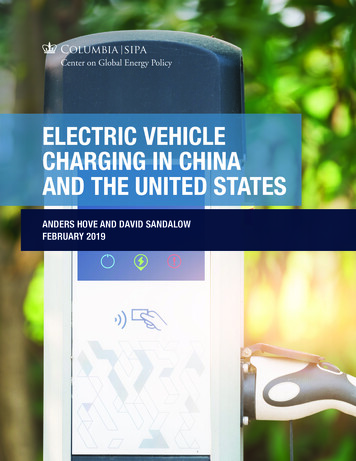
Discussion & ResultsMechanical DesignChoosing a Vehicle to ConvertAn electric conversion will act very similar to the vehicle being converted. A gas guzzlingSUV will have more room for batteries but it will be an electricity guzzling vehicle. A small carwill be more efficient but can’t hold the batteries that a larger vehicle can. The weight of thevehicle will play a pivotal roll in deciding what motor to use and whether or not to use directdrive of a transmission. Rear wheel drive vs. front wheel drive will decide how the motor ismounted and can add complexity. Newer vehicles have computers and modern electronicswhich may never work properly if the internalcombustion engine is removed.Our project timelineconsisted of only nine months to design and construct sowe chose a vehicle to simplify the conversion.We found a 1980 Datusn 280ZX on craigslist that fitour criteria. The engine was not running so the vehicleFigure 1: 1980 Datsun 280zxwas cheap but in overall good condition.It is a five-speed manual rear drive which allowed for a smaller motor to be used (larger motor required fordirect drive) and inline mounting. The electronics were simple, a 3.7 drag coefficient, curbweight of 2800lbs, and enough room for the batteries.Electric MotorInduction and direct current (DC) are the two families of electric motors typically used inelectric vehicles each having their pros and cons. The induction motor works on alternating4
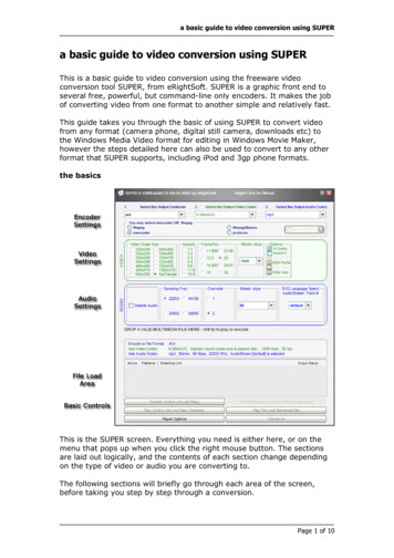
current (AC) power and is controlled using a variable frequency drive (VFD). These motorscome in all different sizes and can provide all of the horsepower and torque needed for anyconversion.Because of how they function, they naturally lend themselves to regenerativebraking using the motor to stop the car (not completely, physical brakes are needed even withregenerative breaking) and recharge the batteries. Drawbacks of induction motors are their costwhere some systems can reach upwards of 25,000.DC motors are more common and the cost of comparable power motors makes them moreattractive than induction motors. These motors fall into two categories of permanent magnet(PM) and series DC. PM have the advantage of regenerative breaking much like the inductionmotor.Choosing a motor will depend on the weight andaerodynamics of the car. The starting torque required tomove our vehicle in first gear with an estimated endweight of 3200lbs is 72 ft-lbs (see calculations inAppendix 2). The torque needed to maintain a speed of65mph in 5th gear is 52 ft-lbs.Based on thesecalculations we chose the series DC motor WarP9 fromWarfield Electric (see performance curve in Appendix1). The motor has the toque to move our vehicle, isFigure 2: WarP 9 Motorspecifically made for electric vehicles, and has a dual shaft for accessory mounting. GrassrootsElectric Vehicles (www.grassrootsev.com) sells this motor for 1670 making it cost competitivewith alternative motors in its same class.5
The WarP9 weighs 158 lbs, has a 9” diameter and is 15”long. The length and diameter of themotor made fit well with our 280zx. The drive end shaft is coupled to the flywheel taken off ofthe original motor. A clutch disc is mounted to the flywheel as it was in the original vehicle andis set inside the bell housing of the transmission. A cover plate was built and the motor isattached to it via a motor cage built from aluminum angle. The commutator end of the motor ismounted to a cross member of the vehicle frame just inside of where the original ICE wasmounted.Rubber pads are placed beneath every mount to isolate some of the vibrations. A brace wasadded to help support the bell housing of the transmission as well.Motor ControllerThe controller has to meet the capacity of the motor being used. Our motor has a voltage limitof 192V and the OEM recommends nothing over 170V. Voltage on the motor is directlyproportional to the RPMs of the motor and amperage has a nonlinear relationship to torque.Several companies manufacture DC motor controllers: Curtis, Alltrax, Kelly Controls, and CaféElectric. The Zilla controller made by Café Electric was our first choice because of its price andpower capabilities.Because they price the controller to affordable to people doing theseconversions, they are highly sought after and there is a waiting list. We chose the Kellycontroller KDH14650, which will have a power output capability of 144V and 250 ampscontinuous for 1,300.The motor controller can limit the performance of the motor andtherefore the vehicle if it is sized too small.The Kelly controller is mounted to an aluminum sheet to aid heat dissipation which isrecommended by the OEM. A 500 amp fuse and a main contactor are mounted to the sameboard. Two LED indicator lights from the controller are mounted in the dash display next to a6
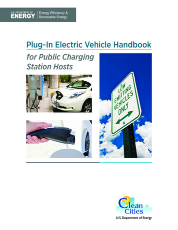
guide for easier troubleshooting from inside the cabin. An RS232 cable is used to change thesettings of the controller such as under or over voltage of the battery pack, throttle type, currentlimitations which is also mounted on the driver side cabin near the floor for easy reprogrammingfrom inside the cabin.Power Steering and BrakesOur original vehicle had power steering and brakes. While removing the ICE we saved thepower steering pump and mounted it onto the driver’s side motor cage. An accessory pulley andbelt provide the power just as it was in the original setup. One drawback is that the car does nothave power steering when the motor is not moving unlike an ICE idling at 700 rpm. Thevacuum assisted brake is solved using a separate 12V vacuum pump commonly used for highhorsepower engines. A PVC tank mounted by the driver side headlight stores vacuum and aswitch will turn on and off our pump keeping 14 to 17 inHg vacuums.HVAC ConsiderationsFree heat that is a normal by product of a 20-30% efficient gasoline engine cannot be totallyreplaced. Electric vehicle conversions such as this would not be ideal for colder climates wherethis heat is essential. Our project uses three 12V 156 watt heaters to provide some heat and awindshield defroster. A heater is mounted under the dash on the driver side and on the passengerside. The third is mounted where the heater core used to be. It is highly recommended that if theheater core is not being used that it be removed because they will smell after some time if leftdormant.This vehicle is going to be a commuter car in the hot climate of the American Southwestwhere air condition is critical in summer heat. The air compressor, condenser, and airconditioning components were salvaged from the original engine. The compressor is mounted to7
the passenger side motor cage and is powered by the same accessory pulley as the power steeringpump. The whole system was rerouted using soft copper tubing and fittings. One option thatwas considered was to run a separate smaller motor for the sole purpose of providing power forthe air compressor. The drawback to using the pulley is that the air will not be compressed whenthe car is stopped. We chose to use the pulley for simplification and cost considerations. Ourvehicle has a manual transmission and the motor can be kept at idle with the clutch disengaged ifit becomes necessary. We will perform tests to see how much the HVAC system will affect ourrange.Figure 3: Motor mounted with power steering (right) and air conditioning compressor (left)Vehicle System MonitoringMuch of the vehicle monitors were for emissions, electronic ignition, and engine monitoring.Removing the engine left a number of the original indicators useless such as oil temperature and8
pressure, fuel gauge, tachometer, battery voltage, and water temperature. The speedometer ofthe car operates on a cable coupled directly to the transmission and is able to be reused.We still need to monitor certain vehicle components such as motor temperature warning,battery life, DC brush indicator, brake vacuum, and tachometer. The only original indicator thatcan be used besides the speedometer is the tachometer; the others will have warning lights andnew gauges added. The tachometer is an important measurement for our motor because it canfly apart if the rpm reaches above 8000. The WarP9 is most efficient between 2500 and 3000rpm so the operator can shoot for this range. The electronic ignition system provided the inputfor the original tachometer which could not be replicated. The needle operates on a DC voltagerange so we mapped the rpm to the appropriate DC voltage. Using a photo sensor and lightreflecting tape on the accessory pulley, we are able to count revolutions and convert thefrequency to the corresponding DC voltage.A generic automotive vacuum gauge works for monitoring the tank vacuum. The Warp9comes with temperature and brush sensors. The motor has H insulation rated up to 180 C andthe temperature sensor is a normally closed switch that opens at 120 C triggering a warninglight in the cabin. The brush sensor will place the full armature to stator voltage across is switchonce the brushes have worn enough to be replaced. A light will come on alerting the operator tochange the motor brushes when this occurs.Electrical DesignBatteriesThere are several options for batteries depending on the conversion budget. Many hybrids usenickel metal hydride to store energy for electric drive. The ideal batteries are the newer LiFeO4because they are light weight, have a large energy density. The disadvantage currently is they are9
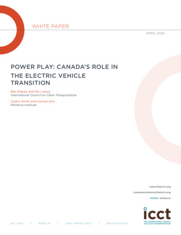
expensive (about 25- 45k depending on the size of the battery pack). Lithium ion batterieshave similar benefits but are still just as expensive. A significant advantage of lithium basedbatteries apart from their light weight and energy density is their 2000 plus cycle life ascompared with 300 to 700 cycles for lead acid. Due to budget constraints keeping the wholeconversion under 10,000, we chose the Trojan J-150 deep cycle lead acid batteries for the 12V150 amp hours (AH) and 700 cycle life.Figure 4: Batteries and motor controller mounted under the hood.The energy of the battery pack is found by multiplying the number of batteries by the volts ofeach battery and by the estimated amp hours.By physical constraints, we were able to fit sixteen batteries in our 280zx. This would give abattery pack of 28.8 kWhr. We have them configured in two rows of eight series connectedbatteries connected in parallel creating a battery pack of 96V and 300 AH at a 20 hour discharge10
rate. At 84lbs per battery, the weight of the total pack is 1344lbs. We expect to replace thesebatteries after two and a half to three years of use.Figure 5: Battery specifications from Trojan Battery CompanyIf a conversion does decide to use lead acid batteries, they should be designed for deep cycle.Although cheaper, regular off the shelf automotive batteries are designed to provide highamperage for the starter motor over a short time and then be recharged by the alternator.Automotive batteries will not last in electric vehicle applications. Batteries should be markeddeep cycle and rated in amp hours instead of only cranking amps.ChargingThe battery charging depends mainly on where the vehicle is being charged and how fast thebatteries can be charged. Lead acid batteries are most efficient with slow charge and discharge.Charging the batteries too quickly can cause a false full as charges build up on the lead plates.The outlet will be a limiting factor as well where most garage outlets have a 15 or 20 amp fuse.11
The end user of the car has a garage electrical outlet with a 20 A fuse. We selected the PFC1500made by Zivan because it can charge at voltages up to 144V and pulls 12A from the wall outlet.Instead of pulling an electrical chord up to the vehicle, we incorporated a retractable chord reelto be pulled from the original gas cap.12V Power SupplyThe original car electronics such as lights, horn, and stereo still operate on 12V DC and aseparate power supply is needed. Currently there are three options to provide this power.First is to have a separate battery. A deep cycle battery will provide enough energy for a dailyuse as long as it is recharged with the rest of the battery pack daily. Some drawbacks to this arethe requirement of an additional battery charger for 12V and a variable voltage as the batterydischarges.A second option is to attach an alternator to the motor and use a regular car battery. This willindirectly take power from the larger battery pack by adding a load on the motor. The energyhas to undergo conversions from electrical to mechanical to electrical which have lossesassociated with each transformation. This is a more convenient solution is that the battery doesnot need a separate charger but it is not ideal.A third option is to have a DC to DC converter. These devices step down the voltage from thebattery pack to 12V. A bonus for this option is that the 12V is constant even when the batterypack voltage decreases or increases. A drawback is that they can be expensive and need to besized to be able to provide enough power to run all of the car electronics. For our project wechose this option because it provides a constant voltage supply for our battery monitoring systemand will not require any additional charging equipment.Battery Monitoring System (BMS)12
On the original vehicle knowing how much gas was left in the tank was easily measured anddisplayed. This is much more complicated and involved with an electric vehicle. The BMS(also known as Battery Management System) is needed to display how much battery energy isleft in the battery pack and to prevent from over discharge of the batteries.Lead acid batteries have a number of issues that will be discussed in this section. The first isthe state of charge (SOC) and depth of charge (DOC). SOC is how full the battery is measuredin percentage. DOC is how discharged the battery is in percentage. Lead acid batteries shouldrarely if ever have a SOC below 20% or DOC above 80%. In some cases if a battery isdischarges below this it might have permanent damage and not be rechargeable. The batteries inmost conversions are the largest expense and need to be protected and there are different ways ofmeasuring SOC.The battery manufacturer measures SOC in two ways as seen in Appendix 3. The specificgravity of a battery is measured by opening the caps and placing a hydrometer inside. How farthe hydrometer sinks in the acid will indicate a state of charge. This is very impractical to beimplemented on a moving automobile. Voltage reading is the second option used by the OEMand is the route we took. Measuring the voltage of each battery when they are wired in series upto 96V presents its challenges. With the use of differential amplifiers and microcontrollers, ourBMS will read the voltages of each battery within 0.05V and display them for each battery ontwo LCD screens mounted on the dashboard. An advantage in monitoring each battery insteadof the entire battery pack has the advantage of identifying problem batteries that needreplacement and how unbalanced the batteries become. When wired in series, the batteriesnearest the cathode will drain more quickly than those nearest the anode. This phenomenon canbe demonstrated and monitored by measuring individual batteries.13
Another method for indicating battery pack status is by measuring the current drawn out ofthem. The fundamental obstacle to this technique is Peukert’s Effect. The capacity of a batterydecreases as the rate of discharges increases. A deep cycle lead acid battery is rated in amphours but the discharge rate should also be displayed. The Trojan J-150 batteries have a 150 Ahr at a 20 hour discharge rate. This means that the battery can provide 7.5 amps for 20 hours. Ifthe battery is discharged with a constant 15amp draw, it would not last 10 hours. Ourbatteries discharged at 75 amps will last 70minutes givingT( I) : an amp hourR I R C nrating of 87.5A-Hr.The capacity decreases at anexponential rate by the equation:Figure 6: Amp hours affected by Peukert’s EffectWhere T is the time the battery will last at the discharge rate I. C is the amp hour capacity givenby the OEM, 150AHr in our case and R is the hours of discharge at the amp hour rate which is20 hours in our case. R will have a normal value of 20 or 100 hours. N is the Peukert’scoefficient that ranges from 1.2 to 1.4 in flooded lead acid batteries.[1]To measure capacity by discharge current is quite involved because the amp hour rating is notconstant. The system would have to measure current for a period of time and integrate thecurrent of the time period giving the amp hours used. The integrated amp hours would have tobe divided by the corresponding amp hour rate at the average discharge current for that period.14
This would give a percentage of the total energy used for that period. The same would have tobe done while charging the batteries. This is possible to accomplish and can be very accurate ifthe Peukert’s coefficient it known. The drawback is that as the batteries age, the efficiencydecreases increasing Peukert’s coefficient. After heavy usage of daily driving over 6 months or ayear the above calculation would be inaccurate displaying more capacity than what is available.The voltage will on the other hand will decrease faster as the batteries age and will still beaccurate. For this reason we chose to measure capacity by voltage.To selectively measure each battery when they are in series up to 96V, we used anessential differential op amp made by Linear Technologies LT1990CS8 which can have up to200V input. We used an Atmega 16 microcontroller and digital multiplexer to obtain anddisplay the voltages on a graphical LCD screen.Figure 7: Four layer PCB layout of BMSSocial impactThe project will have a good impact on the social life of the users. First Substitution ofgas-powered cars with electric vehicles is quite beneficial to your health since the exhaust of15
gasoline-fueled vehicles contains a variety of harmful chemicals that can seriously affect yourhealth. These substances enter our bodies as we breathe and are then transported to all majororgans. The respiratory system suffers the most obvious negative effects, but there are alsoimpacts to blood and coronary systems, and the central nervous system. Last but not least, carexhaust includes carcinogenic chemicals. Second Driving an electric car costs about 0.03 permile, which is about 2 times cheaper than a gasoline-powered car. In certain cities andprefectures, electric cars have discounted or free parking and highway fees, as well as tax breakson the purchase price. The main downside is the initial high cost, but national, prefecture andcity subsidies may get you a discount of up to 50%. Third, Using electric cars can definitelyinfluence your lifestyle. To start with, you’ll make no more trips to the gas station. Instead,you’ll get into the habit of plugging your car in every night at home. With a charging time of 4 –8 hours, and its limited range of 120 km, an electric car can satisfy most of the needs of theaverage urban commuter. But for the occasional trips of more than 100 kilometers, you wouldneed to use public transport or rent a car.SafetySafety was the first concern after obtaining the car. New brake pads and calipers were addedand the rotors were turned. New tires were put on as well. An failure mode and effects analysis(FMEA) was created before any testing to prevent injury and damage,ConclusionThe converted vehicle is in its optimization stages. Our design of experiment consists ofacceleration and top speed tests with varying number of batteries. The range test will also beconducted varying the number of batteries and different noises such as air conditioning andlights. On our initial tests we have observed the phenomenon that the battery closest to the16
cathode side will drain faster than the rest of the batteries placed in series. This will be anadditional benefit to monitoring each battery as not all of them will read the same voltages.Because of this we recommend rotating the batteries every couple of months.References1) Gibson, Chris. “Peukert’s Equation.”04 February 2008.SmartGuage Electronics. http://www.smartgauge.co.uk/peukert2.html Oct 2008.2) Leitman, Seth, Brant Bob. Build Your Own Electric Vehicle. New York Mcgraw Hill. 2ndEd. 2009.AppendixAppendix 1: Performance curve of Warp 9 motor http://www.go-ev.com/images/003 15 WarP 9 Graph.jpg 17
18
19
Appendix 2: Design Calculations[2]20
Appendix 3: State of Charge by voltage of battery aspx 21
guide for easier troubleshooting from inside the cabin. An RS232 cable is used to change the settings of the controller such as under or over voltage of the battery pack, throttle type, current limitations which is also mounted on the driver side cabin near the floor for easy reprogramming from inside the cabin. Power Steering and Brakes