Transcription
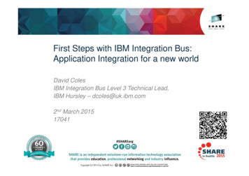
First Steps with IBM Integration Bus:Application Integration for a new worldDavid ColesIBM Integration Bus Level 3 Technical Lead,IBM Hursley – dcoles@uk.ibm.com2nd March 201517041InsertCustomSessionQR ifDesired.
Important Disclaimer THE INFORMATION CONTAINED IN THIS PRESENTATION IS PROVIDED FOR INFORMATIONALPURPOSES ONLY. WHILST EFFORTS WERE MADE TO VERIFY THE COMPLETENESS AND ACCURACY OF THEINFORMATION CONTAINED IN THIS PRESENTATION, IT IS PROVIDED “AS IS”, WITHOUT WARRANTYOF ANY KIND, EXPRESS OR IMPLIED. IN ADDITION, THIS INFORMATION IS BASED ON IBM’S CURRENT PRODUCT PLANS AND STRATEGY,WHICH ARE SUBJECT TO CHANGE BY IBM WITHOUT NOTICE. IBM SHALL NOT BE RESPONSIBLE FOR ANY DAMAGES ARISING OUT OF THE USE OF, OROTHERWISE RELATED TO, THIS PRESENTATION OR ANY OTHER DOCUMENTATION. NOTHING CONTAINED IN THIS PRESENTATION IS INTENDED TO, OR SHALL HAVE THE EFFECT OF:–CREATING ANY WARRANTY OR REPRESENTATION FROM IBM (OR ITS AFFILIATES OR ITS ORTHEIR SUPPLIERS AND/OR LICENSORS); OR–ALTERING THE TERMS AND CONDITIONS OF THE APPLICABLE LICENSE AGREEMENT GOVERNINGTHE USE OF IBM SOFTWARE.
Agenda IntroductionInside IBM Integration BusDevelopmentAdministrationDeveloper EditionIndustry SolutionsKey Usage ScenariosQuestions?
Introduction
What do we mean by Integration? Enterprise systems consist of many logical endpoints– Off-the-shelf applications, services, web apps, devices, appliances, custom built software Endpoints expose a set of inputs and outputs, which comprise– Protocols - e.g. MQ, TCP/IP, HTTP, File system, FTP, SMTP, POP3 etc.– Message Formats - e.g. Binary (C/COBOL), XML, Industry (SWIFT, EDI, HL7), User-defined Integration is about connecting these endpoints together in meaningful ways– Route, Transform, Enrich, Filter, Monitor, Distribute, Decompose, Correlate, Fire and Forget,Request/Reply, Publish/Subscribe, Aggregation, Fan-in, Complex Event Processing
Three strands are involved in connecting applications together.Applications need to talk with each other over a communications protocol. Typicalprotocols in use today include TCP/IP, and higher level protocols such as FTP, SMTPand HTTP.Over the communications protocol applications exchange data, typically in discretestructures known as messages. The format of these messages can be defined from Cstructures or COBOL copybooks (for example), or simply use a standard format such asXML.In order to connect applications together so that their protocols and message formatsinteroperate, mediation patterns need to be applied to one or both systems you’re tryingto connect. These mediation patterns can be relatively straightforward, e.g. routingmessages from one place to another, or the transformation of one message format intoanother to relatively complex patterns such as aggregating multiple outputs from anapplication into a single message for a target system.
Integration solutions are about reducing cost!FileDatabaseWebservice Integration solutions simplify integration!– Avoids rewrites in response to new integration requirements– Simplifies maintenance by reducing expensive coupling– Flexibility adding anonymity between producers and consumers of data– Adds insight into applications and business value they bring
Example integrationFileMr. Smith,Graphics Card, 32,100, 25/12/2011DatabaseWebservice[Customer, Order, Quantity, Price, Date]Analytics order name first John /first last Smith /last /name item Graphics Card /item quantity 32 /quantity price 200 /price date 12/25/2011 /date /order [Customer, Order, Quantity, Price, Date]
An Application Integration Scenario. Application A sends some data to application B. At design time, the two applications agreed on theformat of the data as the ordered set {Customer, Order, Quantity, Price, Date}. Further, the date is inUK format, the price in UK pounds sterling, and all fields are represented by character strings incodepage 500. Finally, the data is delimited using commas. Some time later, Application C is introduced. It needs the same data, but because it is a packagedapplication from a vendor or may be an application that already existed, it expects data to arrive in adifferent format. The date is in US format, the price is in dollars and the data is in XML. So, we now have an integration choice to make. Either application C must be enhanced to supportthe data format between A and B, or application A must be enhanced to support application C's dataformat. (This is an interesting use of the word “enhanced”, but you'll probably want to use it to justifythe expenditure!) By introducing a solution that can mediate between these applications, you can integrate themwithout spending time and money modifying and retesting the existing applications. IBM IntegrationBus is one such solution. In addition, a solution like IBM Integration Bus will also allow you to intercept or record the data as itis processed. Allowing you to satisfy audit requirements or for further analysis for use cases likefraud prevention.
Some examples of integration topologiesBridges Often used for single point-to-pointconnections Usually cheap and quick to configure More difficult to scale to larger numbers ofendpointsinternetGateways Provides connectivity to thirdparties or to a specific class ofendpoint For example, internet, cloud,security, DMZ, B2B Combines simplicity ofconfiguration and a commonlyon-ramp to back-end ESBB2Bcloudetc.Enterprise Service Bus (ESB) Logical construct that combinesmessaging and enrichment Scales very well; can integrate smalland large numbers of endpoints, andcan be easily distributed Often applied as a backbone for aService Oriented Architecture (SOA) Solutions can usually also be appliedto hub and spoke style architectures
Introducing IBM Integration Bus IBM’s Strategic Integration Technology Single engineered product for .NET, Java and fully heterogeneous integration scenariosDataPower continues to evolve for integration gateway use-casesIntegrationGatewayEdgeIntegration BusERP/EIS/CRMFilesWeb 2.0DevicesWeb ServicesRetailMicrosoftMQ, abasesMobileIBM Integration Bus is the new name for WebSphere Message BrokerTechnology progression over 15 years, installed at 2500 customers worldwide across allindustriesFully supported worldwide by IBM global support network, standard 5 3 years support policyVersion to version migration is key design considerationGlobal skills availability - SME’s available globally via IBM and partnersClose interaction with growing and loyal customer base: beta and lab advocacy programsAlso incorporates WebSphere ESB use-cases
IBM Integration Bus Provides endpoints and the ability to connect to other endpoints– Off-the-shelf applications, services, web apps, devices, appliances, custom built software Protocols and Message Formats– Protocols - e.g. MQ, TCP/IP, HTTP, File system, FTP, SMTP, POP3 etc.– Message Formats - e.g. Binary (C/COBOL), XML, Industry (SWIFT, EDI, HL7), User-defined Mediation Patterns– Route, Transform, Enrich, Filter, Monitor, Distribute, Decompose, Correlate, Fire and Forget,Request/Reply, Publish/Subscribe, Aggregation, Fan-in, Complex Event Processing
We can now revist this earlier slide in the context of IBM Integration Bus.IBM Integration Bus enables “universal connectivity” by integrating protocols,message formats and mediation patterns.IIB provides the ability to be an endpoint and to connect to other endpoints.It can do this over a variety of protocols and using a variety of messageformats, sometimes with more than one in use at each time.IIB also supports a wide range of mediation patterns, helping to support theuse of the various message formats and protocols in many ways.As we go through the rest of this presentation we will see how IBM IntegrationBus supports all of these.
A Broad Range of Supported Platforms andEnvironmentsBroad range of operating system and hardware platforms supported– AIX, Windows, z/OS, HP-UX, Linux on xSeries, pSeries, zSeries, Solaris (x86-64 & SPARC), Ubuntu– Optimized 64-bit support on all platforms; 32-bit option available for Windows and x/Linux– Support for Windows 8 and Windows Server 2012; .NET CLR V4.5 included on Windows– Express, Standard and Advanced editions make IIB applicable for all solutions and budgetsTraditionalOSVirtual images for efficient utilization & simple provisioning– Extensive support for virtualized environments, e.g. VMWare, AIX Hypervisor any!– Support for public and private clouds: Softlayer, Pure, non-IBM, RYO etc.– Chef scripts for automated building of flexible IIB images (see Github)– Pre-built images (Hypervisor editions) available on xLinux and AIXIncludes access to full range of industry standard databases and ERP systems– DB2, Oracle, Sybase, SQL Server, Informix, solidDB– Open Driver Manager support enables new ODBC databases to be accessed– JDBC Type 4 for popular databases– SAP, Siebel, Peoplesoft, JDEdwardsTechnology components and pre-requisites (@v9)– Java 7 on all platforms– MQ 7.1 prerequisiteIBM WorkloadDeployerPublic CloudIBM PurePrivateCloud
Inside IBM Integration Bus
Integration Bus Components
We’ll start off by taking a look at the architectural components of IBM Integration Bus. We’ll then see howthese elements are used in more detail. The Integration Toolkit is the development environment. Based on the Eclipse platform, all the objectsrequired to perform application integration using IIB are developed, deployed and tested here. It providesstandard ways to build integration applications, perform version control and provide for the development ofcustom plug-ins, such as resource editors to allow users to create project resources easily. Examples arecustom editors to aid flow creation, ESQL editing and syntax checking, message set modelling, and a raft ofother activities. It includes a unit test broker environment. The integration node (or broker) is the container that hosts integration servers (or exectution groups). Eachserver is an operating system process that contains a pool of threads responsible for running the integrationlogic that is deployed to it. The integration servers directly interact with the endpoints that are beingintegrated. There is also a web user interface that provides administration capability, including monitoring of deployedobjects and the ability to start, stop, delete, deploy, manage workloads etc. The APIs that the web UI uses canbe used by custom administration applications, either through Java, REST or commandline scripts.
Integration Bus Message FlowsOutput target(Failure)Input source Reusable Scalable TransactionalOutput targetTransformOutput target
Message flows provide the processing sequence required to connect applications together. A message flow contains the set of operations required to take a message from an originatingapplication and deliver copies of it, some possibly transformed, to any number of connectedapplications for processing.As a message passes through a message flow, it is transformed and routed according to the nodes itencounters, and the processing decisions made within those nodes. Later we'll see how the nodescan modify the values within, or transform the structure of, a message to provide the datatransformations necessary to drive backend server applications.For a given application scenario, the message flow describes all possible outcomes whenprocessing a message. For example, if the message has a high monetary value, a copy of it mighthave to be routed to an audit application. Or if the message is not well-formed (may be it's notencrypted in the right format), it might be routed to a security application to raise an alert.Equally important is the visualization of the application integration within then organization. Veryoften, for any particular application scenario, the application connectivity requirements (*business*!)is held within the heads of domain experts. Being able to view the integration structure bringsbenefits in scenario understanding, reuse potential, and application architecture/standardsconformance.After a message has been processed by a message flow, the flow does not maintain any state. It ispossible to maintain such state in an external database, or within the message by using anextensible header such as the MQRFH2 or message properties.
Message flows are general purpose, reusable integration applications. If you were designing a general purpose integration application, linking client and serverapplications, the logic would comprise separate routines each performing a well-definedfunction. The input routine would wait for a message, and after receiving it and checkingthe its integrity, (well formed etc.), it would transfer to the next routines to continueprocessing. After performing their processing, (e.g. enriching/reformatting/routing), these routineswould pass control on through to the lowest functional levels, where output processingwould occur. Here, messages would be written to devices, subsequently read byconnected applications. At any level of processing an exception could be raised forsubsequent processing. After the last output routine had completed, control would return back up through thelevels to the input routine. Once here, all the changes would be committed and the inputroutine would wait for more input.
Message flows are transactional.–Message flows provide vital processing and data manipulation and are therefore fullytransactional. A message flow either completes all or none of its processing successfully.–However, if required, individual nodes can elect to perform operations outside of the messageflow transaction. (e.g. audit)Message flows are multithreaded.– Message flow nesting and chaining allow construction of enhanced capabilities.– A given message passing through a series of nodes will execute on a single thread. To allowincreased message throughput, message flows can be defined with many additional threadsassigned to them. Peak workloads use additional threads, which are pooled during inactivity.We'll see more implementation details later. This means application scaling can be anoperational rather than design time decision.Sophisticated flows can be rapidly constructed by linking individual flows together as well asnesting flows within each other.References:– Message Flow overview MKHH 9.0.0/com.ibm.etools.mft.doc/ac00310 .htm?lang en
Message flow example
Here is an example of a message flow.–The ‘Read from MQ Queue’ node tells IIB to take messages from an MQ queue (the name of which isembedded as a property of the node, or overridden by an administrator at deployment time).–The message is passed onto the ‘Is Gold Customer?’node, where a routing decision is made based on a fielddescribed in the incoming message, again which is a property on the node itself. We’ll see exactly how thiscondition is specified later on.–If the described condition holds, the message is routed to the ‘Generate WS Request’ node where themessage is transformed – presumably into an SOAP message that is recognisable by the web service which isinvoked by the subsequent ‘Call WS’ node.–If the described condition does not hold, the message is routed to the ‘Generate batch file’ node, whichformats the message for subsequent output to a file in the ‘Write file’ node.This flow may not tell the complete integration story between the calling application and the target Web Service/Fileapplications. For example, there is no communication back to the calling application to say that the message hasbeen processed (or even received). Nor is there any logic in the message flow to cope with failures – for example, ifthe web service is not available. This is logic that could be incorporated into the flow, but not visualised here forclarity.
Nodes The building blocks of messageflows Each node type performs adifferent (input, output orprocessing) action Many different node types– Grouped into logical categoriesin the editor– Nearly 100 nodes available outof-the-box
Nodes can be grouped in several ways; for example, by where in the flow they are used:– Input nodes do not have input terminals; processing of the message flow starts when a message isretrieved from an input device, for example WebSphere MQ.– Output nodes do not have output terminals (or at least, they are not wired to any other node). The finalstage of output processing is after a message is put using one or more output nodes, and processingcontrol returns to the input node which commits or backs out the transaction. Recalling that a messageflow is analogous to a functional decomposition, it makes sense that the top most level (i.e. the inputnode) controls the overall transaction.– Processing nodes are nodes that are neither input nor output nodes. They will be connected to nodesboth upstream (i.e. towards the input nodes) and downstream (i.e. towards the output nodes). They can also be grouped by the function that they perform.– Protocol-specific nodes give the broker the ability to interact with particular systems, such as MQ andWeb Services.– Transformation nodes will take a message in one format on the input terminal and output a convertedmessage on the output terminal.– Logical constructs give the message flow designer the vocabulary required to solve complexintegration scenarios, for example, the ability to aggregate messages from multiple places or theability to filter messages based on their content. References– More on nodes can be found /SSMKHH 9.0.0/com.ibm.etools.mft.doc/ac04550 .htm?lang en
Message Flow Nodes
Here's a list of the protocol specific nodes built in to IBM Integration Bus V9. For example:–The WebSphere MQ nodes allows Integration Broker to interact with queues on MQ QueueManagers. For example, MQInput is an input node that triggers a flow when a message arriveson a queue; MQOutput puts a message to a queue.–The WebSphere Adapters nodes provides native support in Integration Bus for inbound andoutbound communication with Enterprise Information Systems.–Web Services nodes provide a rich environment for running as a Web Services requestor,provider and intermediary. Support for WS-Security, WS-Addressing, import and export ofWSDL and validation against the WS-I Basic profile. The RegistryLookup and EndpointLookupnodes provide support for WebSphere Registry and Repository (WSRR).–The File nodes are very sophisticated and include support for the FTP and SFTP protocols, aswell as advanced processing scenarios such as record detection. These nodes arecomplemented by additional nodes which provide support for managed file transfer systems(IBM’s MQ File Transfer Edition and Sterling Connect:Direct).–HTTP nodes complement the Web Services capability. Support is provided for HTTP 1.0, 1.1and HTTPS.–JMS nodes work with *any* JMS 1.1 compliant provider.–The EmailOutput node is a highly configurable node that allows e-mail messages to be sentover the SMTP protocol. EmailInput allows e-mails to be received from POP3 or IMAP servers.–TCP/IP nodes allow the Integration Bus to communicate with any client or server talking theubiquitous TCP/IP protocol.–CORBA, IMS and CICS request nodes for integrating with CORBA, IMS and CICS applicationsrespectively.
–––Database nodes allows message flows to interact with many different data sources,including DB2, Oracle and Sybase.Timer nodes provide support for triggering message flows and certain times or intervals.The Routing category allows messages to easily flow around a network, and also allow multiplemessages to be aggregated or propagated in the correct sequence. The Transformation category provides Integration Bus with the capability to transform messagesfrom one format into another. Six ways of doing this are available out-of-the-box. More on these later. Construction nodes– Nodes have error handling as part of their design. If an error is detected within a primitive node(e.g. database error), the message is transferred to the failure output terminal. If the failureterminal is not connected, an exception is generated and propagated back towards the inputnode. There is also a specialized Throw node which allows a flow designer to generate anexception in a controlled way. Nodes can have transaction scope inside or outside of the flow.– A TryCatch node is used to process any such exceptions. Its ‘try’ terminal is used for normalprocessing, but if an exception occurs along this path, the TryCatch node regains control andthe original message is propagated through the ‘catch’ terminal.– If the message reaches the input node, it is subject to "back out" processing. In this case, it willbe propagated down its catch or failure terminal, returned to the input queue, put to a back outor dead letter queue, or discarded, as appropriate.
IBM and third-party extensionsV3.0.0.1 V1.0.0.0 V1.0.0.0Aug 2014Jun 2014 Many other nodes and features available through product extensions WebSphere TX, Tibco RV, VSAM, QSAM Write your own User-Defined Nodes Native node framework available in C and JavaOT4i connector framework provides means to implement full lifecycle, including endpoint discoveryDec 2013
Node erminalsoutputmessagetrees
Message flow nodes provide the individual processing elements that make up a message flow. We've seen that a message flow is the combination of operations required to achieve applicationintegration. We build a message flow from small units called nodes; these nodes represent the baseelements required to connect messaging applications together. Looking at a message flow, you can see several objects identifiable with this processing.– Nodes represent functional routines encapsulating integration logic– Terminals represent the various outcomes possible from node processing– Connectors join the various nodes through their terminals A message processing node defines a single logical operation on a message. A message processing node is a stand alone procedure that receives a message, performs aspecific action against it, and outputs zero or more messages as a result of the action it has taken. The action represented by a message processing node encapsulates a useful and reusable piece ofintegration logic. Nodes can be thought of as reusable components in an integration library.
A node is joined to its neighbours in the data flow through connectors attached toits data terminals. Every node has a fixed number of connection points known as "input" terminals and "output" terminals.These allow it to be connected to its neighbours. Each node normally has one input terminal upon which itreceives messages, and multiple output terminals for different processing results within the node. Differenttypes of node have different numbers of terminals. A connector joins an output terminal of one node to an input terminal of the next node in the message flow.You can leave an output terminal unconnected, or you can connect a single output terminal to more thanone target node. After a node has finished processing a message, the connectors defined from the node’s output terminalsdetermine which nodes process the message next. If a node has more than one output terminal connectedto a target node, it is the node (not you) that determines the order in which the different execution paths areexecuted. If a single output terminal has more than one connector to a target node, it is the broker (again,not you) which determines this execution order. A node does not always produce an output message for every output terminal: often it produces one outputfor a specific terminal depending on the message received. E.g. a filter node will typically send a messageon either the true or false terminal, but not both. When the processing determined by one connector has been completed, the node reissues the message tothe next connector, until all possible paths are completed. Updates to a message are never propagated topreviously executed nodes, only to following nodes. The message flow can only start processing the next message when all paths through the message flow(that is, all connected nodes from all output terminals, as appropriate) have been completed.
ParsersModelInput Message BitBit-streamFredSmith,GraphicsC a r d Parser convertslogical structureto bit-streamParser convertsbit-stream tological structure o r d e r n a m e M r . S m i t h / n ModelOutput Message BitBit-stream
On the previous slide we saw that objects called “message trees” are sent to a node’sinput terminals, and either the same or different message tree is propagated from anode’s output terminals. The message tree is a logical definition of a message processed by the broker. It’s described as atree because messages are typically hierarchical in structure; a good example of this is XML. Othermessage formats too, are also often derived from complex structures which themselves can bederived from complex structures, and so on, which gives them a tree-like shape with leaf nodesrepresenting simple data types. In IBM Integration Bus, parsers have the job of converting between physical messages (bit-streams)and logical trees. When a message arrives at the broker through an input node, the message bitstream is converted into a tree structure by the parser, which typically uses a model to drive the formof the logical tree. Built-in parsers handle well known headers within the message (MQMD,MQRFH2 etc.). Finally the user data is parsed into the tree using the domain parser as identified inthe MQRFH2 (or input node). Message Broker’s built-in parsers support multiple domains (MRM,SOAP, XMLNSC, Data Object, XMLNS, JMSMap, JMSStream, MIME, IDOC, BLOB and XML) toenable parsing of user and industry standard formats. As the logical tree is passed from node to node, the form of the logical tree may change dependingon what the node is doing. When the message arrives at an output node, the parser converts the logical tree back into aphysical bit-stream where it can be output to the external resource, where it can be read by thetarget (receiving) application. However, note that an output node need not indicate the end of a flow;it is possible to output to multiple destinations within a single invocation of a message flow. In thiscase, the logical tree can be passed on to other nodes and manipulated further, even after it hasbeen converted back into a physical bit-stream for this particular output node.
Transport for London
This is a map of the London Underground railway system from 1921. Notice how thelines relate to the physical layout of the stations rather than the logical layout. It makes itreally difficult to work with this map, particularly around the central area. Harry Beck (pictured) produced a new style map in 1933. Beck was an Undergroundemployee who realised that, because the railway ran mostly underground, the physicallocations of the stations were irrelevant to the traveller wanting to know how to get to onestation from another — only the topology of the railway mattered. See http://en.wikipedia.org/wiki/Harry Beck %28graphic designer%29 for moreinformation.
Transport for London
This is Harry’s map from 1933. He had devised a vastly simplified map, consisting of stations, straight line segments connecting them,and the Thames; lines ran only vertically, horizontally, or at 45 degrees. The Underground was initiallysceptical of his proposal — it was an uncommissioned spare-time project, and it tentatively introducedit to the public in a small pamphlet. It was immediately popular, and ever since the Underground hasused topological maps to illustrate the network. In Integration Bus terms, Harry was the “parser” – he took the physical representation of the LondonUnderground and converted into a logical structure. This logical structure is very much easier to workwith. Integration Bus uses logical structures to describe physical data for similar reasons: it makes themmuch easier to work with, particularly when addressing or converting between data elements. We’llsee examples of this later on. See http://en.wikipedia.org/wiki/Tube map for more information.
Message ModelingPhysicalLogical order name first John /first last Smith /last /name item Graphics Card /item quantity 32 /quantity price 200 /price date 07/11/09 /date /order ohn,Smith,Graphics Card,32,200,07/11/09John Smith.Graphics Card.3220020071109.FirstLastStringString Standards based modeldefinitions– XML– DFDL
Here is an example of how a physical data structure could be mapped to a logical tree.– Notice how multiple physical formats can correspond to the same logical tree. Thefirst physical format is an XML structure that shows our Order message. The secondis a comma separated value (CSV) structure of the same. The third comprises a set of fixedlength fields in a custom wire format.– By manipulating the logical tree inside the Integration Broker rather than the physical bitstream, the nodes can be completely unaware of the physical format of the data beingmanipulated. It also makes it easy to introduce new message formats into the broker. Applications have and require diverse data formats.– We all know that XML is the data format that's going to solve every data processing problemthat exists! We also know that "XML ", the follow-on compatible meta format that someone ina research laboratory is working on will solve all the problems we don't even know we havetoday! The fact is that, without wanting to appear cynical, every generation goes through thisprocess. Surely it wa
DataPower continues to evolve for integration gateway use-cases Edge Integration Gateway Integration Bus ERP/EIS/ CRM Files Devices Retail MQ, JMS, MSMQ Applications Mainframe CICS/IMS Web 2.0 Web Services Microsoft Healthcare Databases Mobile IBM Integration Bus is the new name for WebSphere Message Broker