Transcription
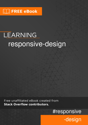
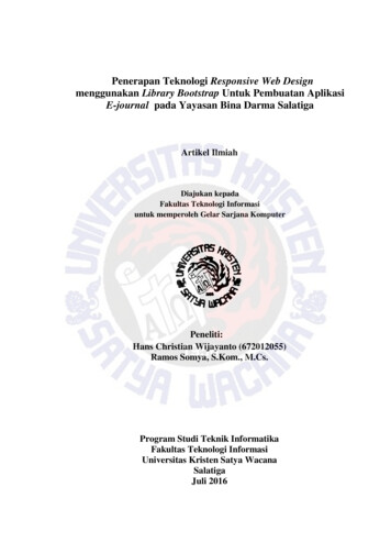
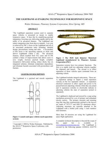
AIAA-2nd Responsive Space Conference 2004-7005THE LIGHTBAND AS ENABLING TECHNOLOGY FOR RESPONSIVE SPACEWalter Holemans, Planetary Systems Corporation, Silver Spring, MDABSTRACT1The Lightband separation system used to separatespace vehicles is presented as means to enableresponsive space. It does this by simplifying payloadintegration, lowering cost, delivering rapidly and by theutility of its advanced features. The Lightband canreduce integration time from days to minutes. Low costis achieved by PSC’s focus on the Lightband and all ofits associated production tasks including: detaileddesign, procurement, testing and sales. A by-productof this focus is the upcoming capacity to stock anddeliver Lightbands within a day. The advancedfeatures, which resulted from five years and 1.5Myielded a litany of improvements that allows users tosave weight, increase payload height, completeinexpensive full-system testing, reduce shock, buy anintegrated solution, eliminate temperature dependenceand eliminate hazards associated with pyrotechnics andfracture.LIGHTBAND DESCRIPTIONThe Lightband is a payload and missile separationsystem.Figure 2 The 38.81 inch diameter MotorizedLightband manufactured by Planetary SystemsCorporation (PSC)Separation systems have two primary functions. Thefirst is to rigidly hold two adjoining vehicles togetherfor shipment and launch. The second is to affectseparation of those vehicles upon command from anadjoining vehicle.The Lightband includes integral subsystems. These are:1) separation springs to impart a small separationvelocity on the two separated vehicles. 2) separationelectrical connectors to allow signal and power to bepassed between adjoining vehicles while they are joinedand 3) separation switches to electrically indicate toadjoining vehicles the state of separation (joined orseparated).The Lightband is deployed and stowed by a snap actingmechanism powered by a set of primary and redundantelectric motors. The primary structure and retainingring (the ring that communicates preload to the leaves)are made of 7075-T7 and 6061-T6 aluminum alloys.Adjoining structures are typically attached to theLightband with a bolted joint using ¼ inch stainlesssteel fasteners.Figure 1 Launch and space vehicles need separationsystems1Copyright 2004 by Walter Holemans. Published bythe AIAA 2nd Responsive Space Conference, withpermission.More than 20 missions are using the Lightband forspace flight application.A complete technical description is beyond the scope p.com. The Lightband iscovered by the following patents: 6390416, 63437701AIAA-2 Responsive Space Conference 2004nd
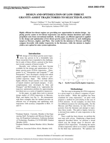
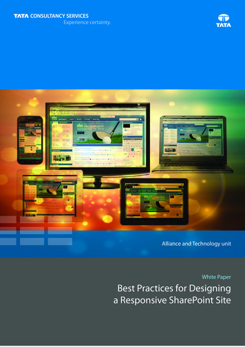
and 6227493. Several other US and internationalpatents are pending.SIMPLE PAYLOAD INTEGRATIONThe Lightband allows a much simpler integrationprocess.Integration is the process of joining two components ofan aerospace vehicle. The task of joining two vehiclesinvolves both the physical act of joining and theverification that the joining is as it should be. Whenjoining two vehicles, alignment has to be set with aprecision on the order of 0.01 inches to assure reliableoperation. The separable electrical connectors must besimultaneously mated without the possibility of pindamage. Clocking (the orientation about the separationvector) must be obvious and failsafe to prevent damage.The separation springs must compress in the matingprocess. The preload force in the joined system has tobe set to narrow limits to assure stiffness and strength.The readiness of the separation initiator must be easilydetermined.Traditional Payload IntegrationA traditionalintegration process occurs in a building at or near thelaunch site. Due to the relative fragility of theadjoining vehicles, particularly the separation system,the process of integration is rigidly controlled by amultidisciplinary team, procedures and specialequipment. Engineers, technicians, customers andquality assurance personnel are often in attendance.Other members of the launch team typically have towait for this process to complete before they canresume vehicle verifications. The infrequency of thisprocess leads to atrophy of integration skills, reenforcing the need use large, and slow teams.Figure 3 A traditionalStarshine-3 on Athena.integrationprocess.Ideal Payload Integration The process to join aerospacevehicles on the deck of aircraft carrier represents anideal with respect to time and cost. The joining of anair-to-air missile to the pylon of an F-18 is completedfrom carrier to aircraft by a team of five in two minutes.Avionics and robust motorized pylon design enablerapid and verified joining.Figure 4 integrating an air-to-air missile to an F-18aircraftIntegration With the Lightband Joining space vehicleswith the Motorized Lightband is, by design anddemonstration, a rapid and easily verified separationsystem. The process shown in the figures below took 3people 45 seconds to complete. The satellites werebuilt by the University of Texas at Austin. They will beseparated and released 80 times on a KC-135 “VomitComet”.Figure 5 The satellites are removed from theircrates, the Lightband halves have previously beenintegrated to adjoining vehicles2AIAA-2 Responsive Space Conference 2004nd
Figure 6 One satellite is place on the otherFigure 8 Push of a button on the controller setsLightbandFigure 7 The satellites are joined using integralclocking and alignment featuresFigure 9 Ready for FlightLOW COSTPSC’s focus on a single product, the Lightband, enabledlow cost. All the production tasks are similar.Design The cross-sections of the Lightband areidentical. Using modern computer assisted design(CAD), new diameter Lightbands are made by changingthe sweep path circle diameters, a variable in the CADmodels.3AIAA-2 Responsive Space Conference 2004nd
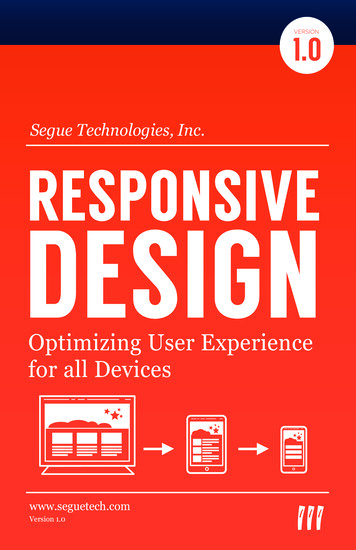
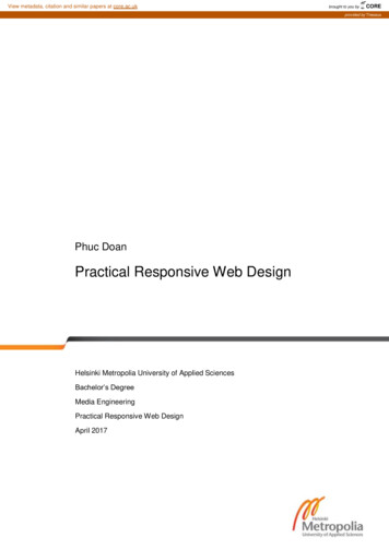
Figure 10 Cross-section of Motorized Lightband.Dimensions are in inches.Because all the subsystems are identical, completingnew assembly drawings only require changingsubsystem quantities. Instead of spending six monthson all custom parts, a new Lightband can be designed ina few man-weeks.five major iterations of the design before the productionefficiency was possible. PSC’s self-serving need toposses a broadly applicable, high performance productthat was not only easy to manufacture, but easy to test,did not come easily. This was due to the inability ofpresent analytical techniques to thoroughly predictperformance of mechanisms. Unlike structural design,which generally benefits from isotropic and continuousmaterial properties, mechanisms are intentionally (to letthem operate) loaded with a series of difficult toanalyze discontinuities. So to come up with a gooddesign, many prototypes had to be made, tested andimproved.In the course of development, manypromising technical solutions were abandoned becausetheir recurring cost proved to be too high. Over timethe trend in the Lightband development has been toincrease specific stiffness, specific strength whilereducing total production, test and integration cost. Themotorized Lightband was the final product of thedevelopment effort. The actual use of Lightband onmany small satellite missions proved effective in givingPSC engineers feedback on areas for improvement.Procurement Several qualified vendors are used tomanufacture all of the Lightband subsystems. BecausePSC is constantly re-ordering or ordering simplevariations of the same part, the vendors maintainproficiency in their programs and tooling allowing themto distribute fixed costs over many orders.Test Fixtures All of the Lightband tests are similar. Theonly variable is the magnitude of test level andLightband diameter. For every Lightband diameterthere is a specific set of tooling to allow rapidintegration to the test fixtures. As a consequence thetest plans become nearly identical, allowingdocumentation efficiency.Sales All nine standard variations of the Lightband havebeen cataloged and placed into a technical brochure.The brochure allows systems engineers to rapidlydown-select. Once a buy decision is made, customerscan order without the encumbrance of statements ofwork or complex procurement vehicles. The Lightbandis listed on the GSA allowing them to streamlineacquisition. While sales may seem unimportant toengineers steeped in system design, program managersappreciate the potential to cut a month off theprocurement effort.Technical Development The technical development ofthe Lightband took five years, 1.5M and a series ofFigure 11 Five Lightbands sequentially developedfrom 1998 to 2002Custom test Equipment Test equipment that allowedrapid testing was designed and built concurrently withthe development of the Lightband. To envelope the4AIAA-2 Responsive Space Conference 2004nd
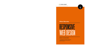
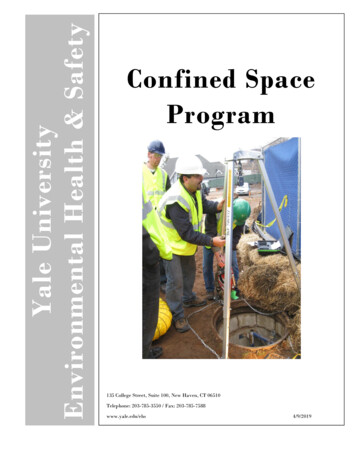
environments the Lightband has to perform in, four testitems were built.The Strength test fixture uses a stiff steel frame andhydraulic rams to apply flight-like loading. Additionaltooling approximates the local stiffness and flatness ofreal space vehicles.Figure 14 Separation Reliability FixtureA thermal vacuum test chamber was made to test theLightband in the vacuum and temperature extremes ofspace. The Lightband is typically cycled eight timesbetween temperature extremes, at 10-6 torr. During theninth cycle, separation is initiated. With the motorizedLightband, the Lightband can be reset, to repeat the testwithout breaking vacuum.Figure 12 Strength test fixtureThe Vibration test fixture is designed to emulate themass properties of adjoined structuresFigure 13 Vibration test fixture, Lightband andelectro-dynamic exciterThe Separation reliability test fixture frictionlessly offloads gravity torques, allowing the Lightband toseparate as it will in orbit. A spherical air-bearingallows pitch, roll and yaw; a planar air bearing allowstranslation. The separating half (supported by the airbearing) is instrumented with an inertial measurementunit, which coupled with measurement of the separatinghalf’s mass properties, allows accurate verification oftip-off rates and delta V. Additional instruments recordtime, current and voltage to separate. The reset-abilityof the Lightband allows engineers to executestatistically significant number of tests (at least 10)yielding maximum, minimum, average and standarddeviation of all of the readings.Figure 15 Thermal Vacuum chamber with 38 inchLightbandRAPID DELIVERYThe aforementioned production efficiencies haveallowed PSC to begin stocking the most populardiameters (15 and 23 inch diameter) By the fall of 2004PSC will be able ship these fully tested Lightbandsfrom inventory. For diameters other than 15 and 23inches, the typical delivery is seven months. Deliverycan be accelerated to three months. Non-catalogLightbands are usually delivered in 8 months.ADVANCED FEATURESThe advanced features of the Lightband enable5AIAA-2 Responsive Space Conference 2004nd
responsive space. Here the Lightband is contrasted to atraditional V-band (sometimes called “Clamp Band” or“Marmon Band”).The most useful feature of the Lightband is its weightsavings. The Lightband weighs 0.36 lbf per inch ofdiameter, while a typical Vband weighs 1.10 lbf perinch1 of diameter. On a 38.81 inch diameter separationsystem the Lightband is 28.7 lbf lighter than a Vband.This equates to a savings of 430,500 in launch costsassuming 15,000 / lb to orbit. Practically, users don’tget this money back; they apply this credit beneficiallyto the rest of their payload.The Lightband is 2.1 inches tall while Vbands range inheight from 4 to 8 inches. The 1.9 to 5.9 inch height2savings can be applied to allow longer or simplersatellite structures and larger stowed solar arrays. In thecramped volume of a payload fairing, several inches ofheight savings is substantial.The Lightband’s design enables inexpensive full systemtesting. Performance can be repeatedly measured,especially when the Lightband is integrated intoadjoining vehicles. The critical item to measure is theseparation indication. Will the space vehicle turn-onafter separation? Will the launch vehicle detectseparation? Other tests include verifying inhibits andenables related to the separation event. Vbands havenot been designed to support repetitive testing. Thehigh tension band usually reaches its fatigue life in tenuses. The need to replenish the pyrotechnic initiatorsand the bolts they cut each cycle adds to cost andpersonnel safety burden. For these reasons, programmanagers and engineers on limited budgets may betempted to minimize Vband testing.For anymechanism, lack of testing reduces confidence level onreliability3. PSC’s use of advanced test equipment hasallowed it to test were traditional Vband suppliers areunable, simply because they have not developed the testequipment.Specifically the separation reliabilityfixture used to rigorously verify separation dynamics.The shock of the Lightband is below 300g while Vbandtypically produce a shock of 1,000 to 5,000 g at theinterface to adjoining vehicles4. Some sensors aresensitive to high shock and are intentionally locatedaway form shock sources. With the Lightband,engineers are free to locate shock sensitive equipmentnext to the Lightband allowing them to make the bestuse of available volume.The Lightband integrates all separation subsystems.This unburdens the engineers of the adjoining vehicles.Since the design and negotiation of separation spring,connector and switch location can involve manyiterations of the engineering teams on both sides of theinterface, the elimination of this time consuming tasksaves time. The Lightband has been designed to allowmany permutations of subsystem placement. Engineerscan place separation connectors at optimal location tominimize wiring harness weight.Further, theseparation springs can be segregated on one side toinduce tip-off. Angled springs can be employed to spina payload up around the spin axis.The time to deliver a Lightband can be 3 months (soon1 day for the most common diameters). The typicaldelivery is 7 months. This compares favorably to atypical delivery of 12 months for a Vband. In the samevein, the time to integrate a Lightband can be 6 manhours for a highly motivated team versus 168 manhours applying traditional aerospace methods and usinga Vband.The Motorized Lightband is fracture proof because theretaining ring is in compression. The retaining ring,which distribute preload to the latching elements, canbe completely severed without separation. On a Vband,however, the tensile band wrapped around all the shoesis susceptible to fracture due to its high stress andbecause it is a mono-filament. Once a crack starts inthe tensile band of a Vband, its growth is acceleratedwith each separation event and thermal cycling. This iswhy Vbands are typically limited to ten or fewer uses.The Lightband employs motors to initiate separationwhile Vbands typically employ pyrotechnics5. The useof motors eliminates the possibility of electro-staticdischarge induced separation while Vband requiresubstantial electronic, range safety and shipmentinhibits. The elimination of the need for safetymeasures reduces cost.The Lightband’s preload does not vary withtemperature because all of the load-bearing elementshave the same coefficient of thermal (CTE) expansion.Preload is the tension or compression in a fastenedstructural joint.Because of CTE mismatch, analuminum joint fastened with stainless steel fastenerswill experience a change in preload with temperature.Changes in preload have a non-linear amplifying affecton stiffness6, the primary design driver of separationsystems. CTE mismatch is important in missions werethe separation event is delayed long enough that theseparation system will cool or heat by 30 degreesCelsius. In most Vbands, the aluminum rings arepreloaded by a stainless steel or titanium band. If theVband gets too hot, preload increases and may lead toactuation. If the Vband gets too cold, preload andstiffness decrease. This can be of particular concern onShuttle missions.If the Shuttle must abort prior6AIAA-2 Responsive Space Conference 2004nd
payload separation, after a cold soak, the Vband mayhave insufficient strength or stiffness to react re-entryloading. When intimately connected to rocket motorcases separation system temperatures can also increasesubstantially and lead to premature separation orweakening of CTE mismatched joints. As an aside, thisis the operating principal of so called frangi-bolts:increase the temperature of a preloaded bolt until itfractures.SUMMARYThe Lightband separation system enables responsivespace by simplifying payload integration, lowering cost,delivering rapidly and by the utility of its advancedfeatures. PSC has spent a substantial amount of timeimproving separation system technology.TheLightband is ready to be adopted by an industryinterested in improving space system performance.ACKNOWLEDGEMENTSubstantial funding and other support came from aSmall Business Innovative Research (SBIR) grant viathe Air Force Research Lab (AFRL). Specifically atAFRL: Jeff Ganley, Maurice Martin and SteveBuckley.Their faith and support is gratefullyacknowledged. Dr Gil Moore of Project Starshine wasinstrumental in helping PSC get flight heritage.1Jarosz, Don (Editor) Marmon Band Primer (SSPP-REF-016), NASA-GSFC, 1997Same as endnote 13Conley, Peter L. (Editor) Space Vehicle Mechanisms John Wiley & Sons, 1998, page 687-6884Conley, Peter L. (Editor) Space Vehicle Mechanisms John Wiley & Sons, 1998, page 2515Same as endnote 16Slocum, Alexander H. Precision Machine Design Prentice Hall, 1992, page 37327AIAA-2 Responsive Space Conference 2004nd
Figure 12 Strength test fixture The Vibration test fixture is designed to emulate the mass properties of adjoined structures Figure 13 Vibration test fixture, Lightband and electro-dynamic exciter The Separation reliability test fixture frictionlessly off-loads gravity torques, allowing the Lightband to separate as it will in orbit.