Transcription
COREMetadata, citation and similar papers at core.ac.ukProvided by e-Prints SotonComparative study of the effective single modeoperational bandwidth in sub-wavelength opticalwires and conventional single-mode fibersYongmin Jung,* Gilberto Brambilla, and David J. RichardsonOptoelectronics Research Centre, University of Southampton, Southampton, SO17 1BJ, UK*ymj@orc.soton.ac.ukAbstract: We present the first experimental comparison of effective singlemode operation bandwidth in sub-wavelength optical wires (SOWs) andconventional single-mode fibers (SMFs). The full transmission spectrum,half-turn bend loss and mode field diameter were measured and comparedfor a variety of SMFs of different cut-off wavelength and a SOW. The SOWwas shown to offer an enormously broadband single-mode operationbandwidth with a larger mode field area than the SMFs. Applications ofSOWs include fiber lasers, sensors, photolithography and optical coherencetomography amongst others. 2009 Optical Society of AmericaOCIS codes: (230.1150) All-optical devices; (060.2340) Fiber optics components; (220.4000)Microstructure fabrication; (220.4241) Nanostructure fabrication.References and links1.2.3.Gerd Keiser, Optical Fiber Communications (McGraw-Hill, 2000).O. S. Wolfbeis, “Fiber-optic chemical sensors and biosensors,” Anal. Chem. 74(12), 2663–2678 (2002).B. A. Flusberg, E. D. Cocker, W. Piyawattanametha, J. C. Jung, E. L. M. Cheung, and M. J. Schnitzer, “Fiberoptic fluorescence imaging,” Nat. Methods 2(12), 941–950 (2005).4. L. Tong, R. R. Gattass, J. B. Ashcom, S. He, J. Lou, M. Shen, I. Maxwell, and E. Mazur, “Subwavelengthdiameter silica wires for low-loss optical wave guiding,” Nature 426(6968), 816–819 (2003).5. G. Brambilla, V. Finazzi, and D. J. Richardson, “Ultra-low-loss optical fiber nanotapers,” Opt. Express 12(10),2258–2263 (2004), http://www.opticsinfobase.org/abstract.cfm?URI oe-12-10-2258.6. M. Sumetsky, Y. Dulashko, P. Domachuk, and B. J. Eggleton, “Thinnest optical waveguide: experimental test,”Opt. Lett. 32(7), 754–756 (2007).7. Y. Jung, G. Brambilla, and D. J. Richardson, “Broadband single-mode operation of standard optical fibers byusing a sub-wavelength optical wire filter,” Opt. Express 16(19), 14661–14667 URI oe-16-19-14661.8. Y. Jung, G. Brambilla, and D. J. Richardson, “Optical microfiber coupler for broadband single-mode operation,”Opt. Express 17(7), 5273–5278 (2009).9. R. Morgan, J. S. Barton, P. G. Harper, and J. D. C. Jones, “Wavelength dependence of bending loss inmonomode optical fibers: effect of the fiber buffer coating,” Opt. Lett. 15(17), 947–949 (1990).10. TIA/EIA Standard, FOTP-80, “Measuring cutoff wavelength of uncabled single mode fiber by transmittedpower,” Feb., 1996.11. M. J. Li, “Bend-insensitive optical fibers simply fiber-to-the-home installations,” Proc. SPIE 7234, 72340B(2009).12. M. Artiglia, G. Coppa, P. Di Vita, M. Potenza, and A. Sharma, “Mode field diameter measurements in singlemode optical fibers,” J. Lightwave Technol. 7(8), 1139–1152 (1989).13. D. Marcuse, “Curvature loss formula for optical fibers,” J. Opt. Soc. Am. B 66(3), 216–220 (1976).1. IntroductionOver the past few decades, standard single-mode fibers (SMFs) have been used widely withinoptical communication systems to transmit high data rate signals with the greatest focus on thenear infrared spectral range (1260 1675 nm) due to the relatively low loss in this wavelengthrange [1]. However, in recent years there has been a continuously growing need for singlemode operation at shorter wavelengths (400 1260 nm) driven largely by advances in highsensitivity optical sensors, lasers, spectroscopy, photolithography, aerospace, defense andbiomedical imaging systems [2,3]. Standard single mode fibers are designed to have cutoffwavelength around 1.26 µm and the development of specialty single mode fibers with short#114155 - 15.00 USD(C) 2009 OSAReceived 16 Jul 2009; revised 19 Aug 2009; accepted 28 Aug 2009; published 2 Sep 200914 September 2009 / Vol. 17, No. 19 / OPTICS EXPRESS 16619
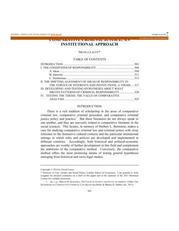
wavelength cutoffs is necessary. There are few kinds of commercial specialty fibers that canprovide a short-wavelength cutoff – referred to by several different names such as “Selectcutoff SMF”, “Visible fiber” and “RGB fiber”. Unfortunately, engineering a short wavelengthcutoff inevitably requires fibers designs characterized by a very small core diameter and arelatively small refractive index difference ( ) between core and cladding. This fact leads toweaker mode field guidance and increases the external bend sensitivity of the fiber at longwavelengths, which results in notably reduced operating spectral window. For example, SMFwith a cutoff wavelength of 780 nm (Nufern 780HP) has a 5µm core diameter and can beoperated within a very limited spectral region extending from just 780 to 970nm. Comparedwith conventional telecom SMF (Corning SMF28), this single mode operational bandwidth isconsiderably reduced from 415nm to 190nm. The bandwidth can be substantially less than100nm when the cutoff wavelength is further shifted to shorter wavelengths. Furthermore, thereduced core diameter and numerical aperture dictate the need for high-precision corealignment processes when splicing and can result in both fiber handling and power penaltyproblems within many practical applications.The authors have recently proposed and successfully demonstrated the use of extremelythin sub-wavelength optical wires (SOWs) [4–6] as an efficient way to provide higher-ordermode filtering in multimode waveguides [7,8] and have shown that this can be used to obtainbroadband single-mode operation of a fiber at short wavelengths, or over a wide range ofwavelengths. The approach relies simply on filtering higher order modes in a multimodewaveguide by integrating a single-mode SOW section within the fiber which incorporatesspecific taper transitions (adiabatic for fundamental mode but non-adiabatic for higher-ordermodes) that minimize re-excitation of the filtered modes. This can greatly enhance the singlemode operation of the multimode fiber while still maintaining large mode field in the lengthsof fiber both before and beyond the SOW. In this study, we have experimentally compared thesingle-mode operational bandwidth of a SOW with several commercial SMFs developed andsold for short-wavelength applications. The full transmission spectrum, half-turn bend lossand mode field diameter of each fiber was tested and compared with those of the SOW. TheSOW was found to offer an enormously broadband single-mode operational bandwidthrelative to the SMFs. The large mode field area and robust stability of single mode operationshould prove beneficial for various applications in fiber lasers, sensors, photolithography andoptical coherence tomography.2. Optical characterization of the SOWs and conventional SMFsA schematic diagram illustrating the principle of higher-order mode filtering using a SOW issummarized in Fig. 1. As described in reference 7, the higher-order modes present at the inputfiber can be effectively suppressed by controlling the biconical taper transition profile (byensuring an adiabatic transition for LP01 but non-adiabatic transition for higher-order modes)and the diameter of the SOW in the waist region. This suppresses the propagation of higherorder modes along the entire length of the SOW and constrains the number of guided modes[7]. As shown in Fig. 1b, a standard telecom SMF (Corning SMF28) shows abrupt anddiscrete transmission power drops near the cutoff wavelengths (λc LP11, λc LP21, λc LP02) andthe single mode operational bandwidth is restricted by the higher-order mode cutoffs at shortwavelengths. With a SOW, however, all higher-order modes are strongly attenuated orstripped out of the fiber and a pure single mode beam is obtained over a broad spectralwindow (400 1700nm). No higher-order mode cutoffs are observed in the transmittedspectrum at any wavelength (Fig. 1c).#114155 - 15.00 USD(C) 2009 OSAReceived 16 Jul 2009; revised 19 Aug 2009; accepted 28 Aug 2009; published 2 Sep 200914 September 2009 / Vol. 17, No. 19 / OPTICS EXPRESS 16620
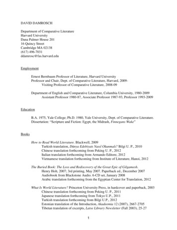
LPhigher LP01 LPhigher modes LP01 Taper regionUniform waistregionAdiabatic (LP01)Non-adiabatic (LPhigher)Taper regionAdiabatic (LP01)Non-adiabatic (LPhigher)(a)-50-50with SOW-60-60λc LP02λc LP21λc LP11-70Two moderegionMore than threeSingle moderegion-80-904006008001000120014001600Oupput power [dBm]Output power [dBm]SMF28-70Broadband single mode range(400 1700 nm)-80-9040060080010001200Wavelength [nm]Wavelength [nm](b)(c)14001600Fig. 1. (a) Schematic diagram of the sub-wavelength optical wire (SOW) for higher-order modefiltering. The biconical SOW with specially designed transition taper and very-thin taper waisteffectively suppresses any higher-order modes at the fiber input and provide broadband singlemode operation at the output. The transmission spectra of standard telecom fiber at the input(b) and output (c) are also compared.2.1 Transmission spectra and bend lossesIn order to experimentally quantify and compare the single mode operation bandwidth of aSOW with several commercial SMFs, the full transmission spectra and bend loss propertieswere examined using an incoherent white light source and an optical spectrum analyzer. Inour experiment, the SMFs have various higher-order mode cutoff wavelengths ranging from450nm to 1260nm and core diameters between 3.3µm and 8.3µm. As shown in Fig. 2, thesingle-mode operational bandwidth is limited by the higher-order mode cutoff (λc-LP11) at shortwavelengths and by the fundamental mode cutoff (λc-LP01) at long wavelengths. For a shortwavelength cutoff SMF, a relatively small core diameter and a low refractive index difference( ) between core and cladding lead to weaker mode field guidance and result in increasedbending sensitivity for the fiber in the long wavelength region, which results in a noticeablyreduced operational spectral window. For example, SMF with a cutoff wavelength of 630 nm(Fig. 2b) has a 4µm core diameter and can be operated within limited spectral regionextending from 600 to 770nm. This single mode operation bandwidth (170nm) is considerablysmaller than the 415nm bandwidth observed in conventional telecom SMF (Fig. 2e). Thebandwidth can be less than 100nm when the cutoff wavelength is further shifted to shorterwavelengths. Another noticeable point is that for the 1µm SOW there is no higher-order modecutoff as observed in the SMFs and the optical bandwidth is simply limited by the bend lossedge of the fundamental mode at the long wavelength. The SOW, as previously discussed,provides a significant enlargement of the optical bandwidth and can be used for shortwavelength or broadband single-mode operation. When reducing the bending curvature, somespectral transmission oscillations are observed near the bend loss edges. It is mainly due to thecoupling between the fundamental core mode and whispering gallery cladding modes due tolight reflection from the boundary of the coating/air and cladding/coating interfaces [9].#114155 - 15.00 USD(C) 2009 OSAReceived 16 Jul 2009; revised 19 Aug 2009; accepted 28 Aug 2009; published 2 Sep 200914 September 2009 / Vol. 17, No. 19 / OPTICS EXPRESS 16621
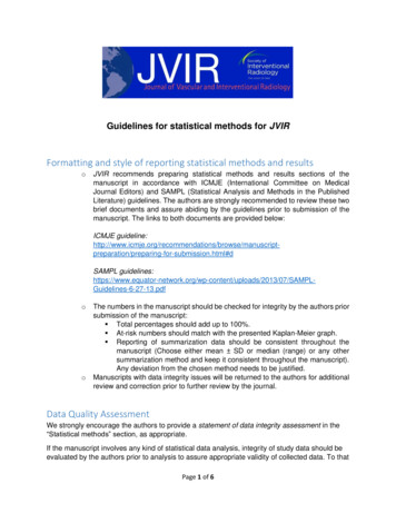
Bend dia. (D)inf503020151086 mmSM450-60-70-50Transmission [dBm]Transmission [dBm]-50-80630HP-60-70λc LP01λc elength [nm]Transmission [dBm]Transmission [dBm]-60inf503020151086 mm-80-90400800100012001400600800Transmission [dBm]Transmission [dBm]λc LP21600λc LP1180010001200Wavelength th [nm](c)-801400inf503020151086 mm-70-904001600SMF28inf503020151086 mm1600-60Wavelength ngth [nm](a)-50-50inf503020151086 mmSMF28 with SOW (D 1µµm)-60-70-8014001600-90400inf503020151086 mm600No λc higher80010001200Wavelength [nm](f)Fig. 2. Full transmission spectra and bend loss properties of various kinds of short-wavelengthcutoff SMFs and a SOW. For a 1µm SOW, there is no higher-order mode cutoff as observed inthe SMFs at short wavelengths and the bandwidth is limited simply by the bend loss edge of thefundamental mode at long wavelength.For a more visual representation of the data, we have produced a comparison chart thathighlights the effective single mode operation bandwidths of a SOW and several commercialSMFs as shown in Fig. 3. The higher-order cutoff wavelengths of the fibers are determined bythe transmitted power method in accordance with the TIA standard [10] and bend loss edgesof the fundamental mode are established by assuming a maximum tolerable bend loss of 3-dB.As expected, the single mode range of commercial SMFs is limited by two cutoff wavelengths(λc-LP01, λc-LP11) and which is easily influenced by the bend diameter. For the case of SM980(Fibercore inc.), the optical bandwidth is decreased from 815nm to 277nm as the bendingdiameter decreases from infinite to 6mm. For practical handling conditions and applications, a10mm bending diameter tolerance is required however SM980 fiber provides only 427nmoptical bandwidth at this bend diameter. Other SMFs also show very restricted optical#114155 - 15.00 USD(C) 2009 OSAReceived 16 Jul 2009; revised 19 Aug 2009; accepted 28 Aug 2009; published 2 Sep 200914 September 2009 / Vol. 17, No. 19 / OPTICS EXPRESS 16622
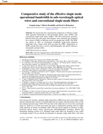
bandwidths for these bending conditions, i.e. SM450 (135nm), 630HP (296nm), 780HP(389nm), SMF28 (384nm). Note that a 1µm SOW presents a bandwidth greater than 954nmfrom 400nm to 1354nm, which is three to four times larger than the SMFs. We expect that thewideband single mode operation can be further enhanced with bend-robust fibers [11].infinfinf1600infWavelength 0630HP780HPSM980SMF28with SOWFiber TypesFig. 3. Comparison between the effective single-mode operation bandwidths of several SMFsand a telecom fiber with a SOW filter for different bend diameters.2.2 Mode field diameter (MFD)In order to compare the mode field diameter of the fibers, we first calculated the effectivemode field diameters from the data sheet of the fibers and a commercially available opticalfiber design program (Optiwave Optifiber). As depicted in Fig. 4, the MFD obtained from theMFD [µm]1086SM405630HP780HPSM980with SOW44006008001000120014001600Wavelength [nm]Fig. 4. Measured (symbol) and simulated (line) mode field diameter comparison for severalSMFs and for a telecom fiber with a SOW filter.SOW is roughly two times larger than those of the short-wavelength cutoff SMFs. This ismainly due to the fact that the SOW is made in SMF28 fiber, which has a relatively large corediameter and refractive index difference. In addition, we experimentally measured the MFDby analyzing the far-field radiation pattern emerging from the fibers (symbols) and comparedwith the simulated results in Fig. 4 (continuous lines) [12]. The measured MFDs agree wellwith the simulated results and the distinctive large diameter of the SOW at short-wavelengthsis confirmed.#114155 - 15.00 USD(C) 2009 OSAReceived 16 Jul 2009; revised 19 Aug 2009; accepted 28 Aug 2009; published 2 Sep 200914 September 2009 / Vol. 17, No. 19 / OPTICS EXPRESS 16623
2.3 Bending loss measurement of different LP modes in fibersThe higher-order mode-filtering feature of a SOW can provide another useful function toseparately measure the bending loss of individual LP modes in fibers. In Fig. 2(e), the opticalbend loss measurement in the dual mode operation region (830 1260nm) of the telecom fiberinvolves both the fundamental LP01 and the second-order LP11 mode (SMF: LP01 LP11).However, in Fig. 2(f), a SOW eliminates the LP11 mode, permitting selective observation ofthe LP01 mode (SOW: LP01). Therefore, we can get separate information about the bendingproperties of LP01 and LP11 by comparing the measured data. The measured bend losscoefficients of the LP01 and LP11 mode for wavelength of 0.9, 1.0 and 1.1µm are shown in Fig.5 (symbols) and compared with the simple formula (lines) introduced in Ref. 13. It has beenfound that the LP11 mode shows higher bend loss at the same bend diameter but a lowerattenuation slope. The technique can be further extended to higher-order mode analysis bydeveloping and optimizing an adiabatic taper shape for fundamental and selected higher-ordermodes.LP01108LP01LP11 (at λ 0.9µm)LP11 (at λ 1.0µm)LP01LP11 (at λ 1.1µm)Ln α6420-201020304050Bend diameter [mm]Fig. 5. Comparison of bending loss coefficients for LP01 and LP11 mode in the telecom SMF(Corning SMF28): symbols and continuous lines represent experiments and simple model ofRef. 13, respectively.3. ConclusionIn this paper we have presented a comparative study of the effective single-mode operationalbandwidth of a SOW with several commercial SMFs. The full transmission spectrum, halfturn bend loss and mode field diameter were characterized and the SOW showed anenormously broadband single-mode operation bandwidth with larger mode field area relativeto the SMFs. The peculiar characteristics provide a new means to increase the spectraloperation bandwidth of several fiber optic components, in many cases limited only by theintrinsic nature of the fundamental mode in the fibers used. Additionally, the higher-ordermode filtering feature of a SOW can provide a useful route to separately measure the bendingloss of individual LP modes in fibers.AcknowledgementsThe authors thank the Engineering and Physical Sciences Research Council UK for financialsupport; GB gratefully acknowledges the Royal Society for a University Research Fellowship.#114155 - 15.00 USD(C) 2009 OSAReceived 16 Jul 2009; revised 19 Aug 2009; accepted 28 Aug 2009; published 2 Sep 200914 September 2009 / Vol. 17, No. 19 / OPTICS EXPRESS 16624
Gerd Keiser, Optical Fiber Communications (McGraw-Hill, 2000). 2. O. S. . optical communication systems to transmit high data rate signals with the greatest focus on the near infrared spectral range (1260 1675 nm) due to the relatively low loss in this wavelength range [1]. However, in recent years there has been a continuously growing need .