Transcription
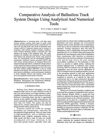
Technical Journal, University of Engineering and Technology (UET) Taxila, PakistanISSN:1813-1786 (Print) 2313-7770 (Online)Vol. 22 No. 4-2017Comparative Analysis of Ballastless TrackSystem Design Using Analytical And NumericalToolsM. N. A. Raja1, U. Rashid2, U. Sajjad31,2,3University of Management and Technology, Lahore, Pakistan2civil.cod@umt.edu.pkspeed reaches its critical value, leading to possible trainderailment and track damages [ii]. Conventionalballasted railway tracks demand a lot of maintenanceworks due to uneven settlements of the ballast duringoperation. Existing experiences show this kind ofmaintenance work is significantly increased for highspeed lines [iii, iv]. As comfort safety and economy areprimarily the most important, state of the art ballastlesstrack constructions offer therefore an alternativesolution due to the enormous reduction of maintenancework and the long service life with constantserviceability conditions [v]. The ballastless or slabtrack is a concrete or asphalt surface, replacing thestandard ballasted track. In ballastless track systeminvolving CRCP investment costs are higher and themaintenance costs are lower and the application ofCRCP is limited to heavily loaded pavements Concreteis the prevailing material in slab track applicationsthroughout the world. Asphalt has been used less ascompared to concrete, as a material for slab trackconstructions due to its high construction demands.Continuously reinforced concrete pavement (CRCP) isthe technology used for ballastless tracks. The absenceof the transverse contraction joints and a well-definedpattern of transverse cracks are the major attributes thatidentify CRCP. [vi].Taking care of economic boundary conditions andto increase the acceptance of ballastless track systems,Finite Element Models (FEM) is among the bestsolution to optimize the design of the ballastless trackcross-section based on the selected parameters. Thisoptimization can be done by a comparative analysisbetween analytical (Westergaard and Zimmerman) andnumerical (FEM) approaches. Sofistik is Europe'sleading software (FEM-based) for analysis, design anddetailing of construction projects worldwide. For thispaper SOFiSTiK is the main object of utilization andwill be used throughout the work.Abstract-Railways is becoming faster, with high speedrunning vehicles exerting wheel loads on tracks couldbecome critical for track quality and the overall lifecycle. Tocope with such high loads, state of the art ballastless tracksystems could be a long-term solution and to increase itsacceptance under limited economic boundary conditions.Finite Element Modeling (FEM) is powerful tool thatoptimizes the design of the ballastless track. This studyexamines the reliability and verification of Finite element(FE) Models with analytical tools. Firstly, using analyticaltools, the Zimmermann and the Westergaard methods,continuously reinforced concrete pavement (CRCP) slabwith various cracking distances are designed followed bynumerical design and analysis. Comparative design analysisis then carried out between analytical and numerical tool toevaluate the impact of input parameters on each of the tools.The finite element package SOFiSTiK is used to modelballastless track design. The verification of FE- model is alsodone based on calibrations, results and boundary conditionsto check reliability, behavior and working. Lastly authorgives some guidelines for the model verification.Keywords-Ballastless Track System, Finite ElementModeling, Westergaard and Zimmerman Methods,Continuously Reinforced Concrete PavementI. INTRODUCTIONRailways have distinct advantages over othertransport modes such as it's more efficient in terms offuel costs and economy over longer distances, safety,reliability and speed, which is achieving new horizons.Railways is becoming faster and due to exponentialincrease in the number of people using railways, theneed to maintain the quality of travel is believed to bemore than ever before. The quality can only beimproved by constant improvement in the technicaldesign for both vehicles and tracks [i].Countries around the world are stronglydeveloping rail transportation, especially thedevelopment of high-speed rail. There are many formsof high-speedrailway, such as ballasted track,ballastless track, magnetic suspension railway, etc.High speeds and heavy loads of trains are usuallya c c o m p a n i e d w i t h l a rg e v i b r a t i o n s i n t h etrain–track–ground system, especially when trainII. Lfqbo r REVIEWThe ballastless or slab track is a concrete or asphaltsurface, replacing the standard ballasted track. InBallastless track rails and sleepers are embedded in2
Technical Journal, University of Engineering and Technology (UET) Taxila, PakistanISSN:1813-1786 (Print) 2313-7770 (Online)concrete and can't be adjusted once laid. Therefore, itmust be laid within a tolerance level limit of 0.005 m.As the structure is made of stiff and brittle materials, therequired elasticity can be obtained by introducingelastic components below the rail or/and the sleeper[vii]. Typical ballastless track is shown in Fig. 1.Vol. 22 No. 4-2017reinforcement is located (about) mid-depth within theconcrete layer. A CRCP does not contain any transversejoint as shown in Fig. 3. In general, compared to JPCP,the CRCP investment costs are higher and themaintenance costs are lower. [ix].Longitudinal Joint (with tiebars)Continuous LongitudinalReinforcement(Deformed Bars)Typical Crack Spacing(0.9 to 2.4 m)Fig. 3. Design characteristics of CRCPFig. 1. Typical Ballastless track SystemSome of the main characteristics are:Reinforcement does not deal with stresses introducedby traffic loadingBecause of short crack spacing ( 5m) thermalstresses introduced by temperature differences Δtbetween surface and bottom of the concrete pavementdue to heating and cooling (warping and curling) aresmaller than for conventional JPCP (slab length 5m).Consequently, slab thickness can be reduced by about10% to 20% compared with JPCP (Slab length 5m) forsame traffic loading [x]Reinforcement controls transverse cracking due toshrinkage and temperature changes in such a way thatcrack width is not exceeding 0.5mm and crackdistribution along the pavement is uniform. Crackdistance shall be much shorter than 5m but not shorterthan 0,5mIn slab track construction, ballast used in commonrailway is replaced by a more durable supportivematerial such as concrete or asphalt. To achieve therequired level of track elasticity for wheel/rail systems– normally provided by ballast – slab track constructionmust use an elastic rail pad for the rail support points.Supportive forces are thus distributed to adjoiningsupport points. The construction principle behind slabtracks is a layered structure with a gradual decrease instiffness level from top to bottom: Rails with railfastening to the supportive layer.[viii]. See Fig. 2Rails and Rail Fastening systemConcrete supportive layer (CSL) or asphalt supportivelayer (ASL)Hydraulically-bonded layer (HBL)Frost protection layer (FPL), Subgrade foundation.Top of rail-hhUIC 60 railModulus ofelasticityCBLIII. ANALYTICAL DESIGN OF BALLASTLESSTRACK SYSTEMUIC 60 railSleeperE1CBLABLSleeperSuperstructureTop of railBallastless track systems with continuouslyreinforced concrete pavements (CRCP) overlaid by thelayer of Cement treated base (CTB) and unboundgranular based layer are the case study. Ballastless trackwithout sleepers but direct fixation (discrete rail seats)is considered using UIC (French: Union Internationaledes Chemins de fer) 60E1 rail as shown in Fig. 4.E2E3FPL / substructureSubgradeDesign without sleepersDepthFPL / substructureE4E1 E2 E3 E4SubgradeSubstructureHBLHBLDesign with sleepersFig. 2. Usual Construction Profile of Ballastless tracksystem [Darr, 2000]In practice the application of CRCP is limited toheavily loaded pavements. Continuously reinforcedconcrete pavements (CRCP) have a small amount oflongitudinal reinforcement (around 0.6 to 0.7% bycross-sectional area) for controlling the crack pattern,i.e. the crack width and the crack spacing. The3
Technical Journal, University of Engineering and Technology (UET) Taxila, PakistanISSN:1813-1786 (Print) 2313-7770 (Online)Vol. 22 No. 4-2017Rail seat loads are calculated at 11 support pointswith load acting directly over support point So (Interiorof slab)Using input parameters, the elastic length of railUIC60 RailCRCPAs seat load S c.Y and deflection.Load, Q is increased by both dynamic and curvature(outside rail) by the factors of 1.5 and 1.2 respectively.While for inner side rails curvature factor of .8 is beingused.Maximum Seat load S0 under load Q2 consideringfactors of 1.2 and 1.5 for curves and dynamic loadingcomes out to be S0 101000 N using following wheelload pattern over the support points.All the supportpoint forces and deflections due to adjacent loads atoutside and inside rail are calculated.See below Table I & Fig. 7CTBSub-GradeFig. 4. Ballastless track without sleepersTABLE ISUPPORT POINT FORCES AND DEFLECTIONSRail SeatRail SeatDeflectionRail SeatSi SupportSi' Support[mm]Load [kN]Point onPoint onOutside rail Outside railOutside railInside railFig. 5. Model UIC 71DeflectionRail Seat[mm] Load [kN]Reduced Reducedby .8/1.2by .8/1.2(Inside rail) (Inside 333.2Fig. 6. Pattern of wheel load over the support points[Lehrstuhlfür Verkehrswegebau, 2014a]For the calculations following parameters hadbeen used:Rail 60E1Dynamic spring coefficient of Cdyn 40 kN/mmContact area 150x150mmConcrete slab with E1 34000 N/mm2Cement Treated Base with E2 5000N/mm2Unbound layer with Es Ev 120 N/mm2Spacing between rail pads 650 mmPoisson's ratio of concrete slab μ1 .16I 30550000 mm4 for Rail profile 60E1E 210000 N/mm2Rail seat loads are calculated involvesdimensioning of ballastless track system. Procedureincludes distribution of rail loads into single loadswhich are further calculated as a rail seat loads.Fig. 7. Support point forcesIV. NUMERICAL DESIGN OF BALLASTLESSTRACK SYSTEMThe aim of this chapter is to understand theprocedure to analyze the ballastless track system bydeveloping 2D FE-Model of a slab using SOFISTIKSoftware.[xi] The model clarifies and verifies thetheoretical/analytical analysis as discussed in previous4
Technical Journal, University of Engineering and Technology (UET) Taxila, PakistanISSN:1813-1786 (Print) 2313-7770 (Online)Vol. 22 No. 4-2017section.The 2D slab as per required slab length and widthof slab track is drawn and the loads/seat loads areplaced at their respective support points in Sofiplus asshown below in Fig. 8. After deciding the density ofmeshing, the model is imported to SSD. The Fig. 9 isshowing the slab track model in SSD after gettingimported from CAD tool and then linear analysis istaken place.Fig. 10. Analytical Model – WestergaardFig. 11. Calibrated Model in SofistikAnalysis of point and area loading with same inputparameters showed little difference between the outputresults primarily due to relatively smaller contact areaof 150 x 150 mm as shown in Fig. 12.Fig. 8. 2D Slab/Pavement Model in SofiplusFig.12. Area vs point loadFig. 9. Slab/Pavement Model in SSDDifferent meshing sizes/densities were analyzedto describe the effects on the output results. Analysisshowed application of load changes with the change indensity thus causes sharp decrease or increase in theoutput values.Different parameters were analyzed individuallyto see the behavior of model in SOFiSTiK includingcalibrating the slab model in SOFiSTiK with slabdesigned analytically. Different software parametersand their effect on the model were also studied. Actualbending tensile stress caused by single wheel acting inthe centre of a slab was calculated with the Westergaardtheory (Infinite slab size). The SOFiSTiK model wasthen calibrated by increasingthe slab size with loadacting at the centre until it reached the analytical stressvalue as can be seen in Fig.10 and Fig. 11.A. Load At Intersection Of ElementsWhen changes in density of meshing caused loadto act at node, a sudden increase in stresses were foundthus a consistency of output results must be verified byanalyzing meshing behavior. This loading position typewas considered throughout in calculations as can beseen in Fig. 13.5
Technical Journal, University of Engineering and Technology (UET) Taxila, PakistanISSN:1813-1786 (Print) 2313-7770 (Online)Vol. 22 No. 4-2017A. Actual And Allowable Transversal/LongitudinalStressesFig.15 and 16 are showing both, analytical andnumerical designs are 'ok' and within the limits ofallowable stresses for a slab length up till 4550mm thusexhibiting same trend. It is also clear from both figuresthat longitudinal stress is the decisive stress than thetransversal stress. A difference in stress values can beseen between analytical and numerical actual stresseswhich are due to the fact that analytical design is basedon infinite slab size and to make the differences less,calibration is needed.Fig. 13 Load acting at nodeB. Load Acting At The Center Of ElementWhen changes in density of meshing caused loadto act at centre of an element, a sudden decrease instresses were found which can be seen in Fig. 14.Fig. 15. Actual & Allowable transversal stressesA. Vertical StressesBoth actual analytical and numerical verticalstresses are below the allowable vertical stress atoptimized thickness thus complimenting each other.The vertical stresses from numerical tool are constantin nature while analytical values increase with theincrease in slab length, as shown in Fig. 16.Fig. 14. Load acting at centre of elementBased on the study done in this chapter these aresome of the important findings: Prior to confirmation results of stresses, suitablemeshing density should be decided carefully toavoid sudden changes in the results due to changesin loading patterns. Here in this study load positionat intersection of elements – nodes are consideredfor the calculations. Model needs adjustment to be comparable withtheory; calibration does the role and shows howSofistik model can be made compatible withtheoretical results. Sofistik results shows with 150x150mm railcontact area, any loading type between rectangularand point can be considered for the design. Behavioural studies ensure consistent results.Fig. 16. Actual & Allowable longitudinal stressesAs the length increases the difference betweennumerical and analytical vertical stresses becomelesser because of the UIC 71 loading pattern. Fig. 17shows, in analytical design, relatively higher deflectiontrend in smaller lengths which gradually becomeslower with the increase in length because of the lowereffect from the neighboring seat loads (as they aresmaller in magnitude).V. COMPARATIVE ANALYSIS OF RESULTSResults from analytical and numerical studies arecompiled together to understand their relation.Comparative analysis has been performed based onanalysis of both analytical and numerical methods andthe important conclusions from the study are discussedas follows.6
Technical Journal, University of Engineering and Technology (UET) Taxila, PakistanISSN:1813-1786 (Print) 2313-7770 (Online)Vol. 22 No. 4-2017These differences between analytical andnumerical could be understood from two theories. Firsttheory refers to the geometry of a slab, Westergaardapproach doesn't consider slab size rather size of a slabis considered infinite. Similarly, Zimmerman approachonly considers width of slab. Second theory deals withthe type of loading as mentioned in chapter 4, there aredrastic changes in stress values with the change in loadtype e.g. load acting at a node.So to verify the SOFiSTiK model with analyticalresults, the calibration is done based on both theoriesand the study being already discussed in chapter 5.Comparative and closer results are found oncemodel is adjusted and calibrated with analytical valuesas shown in tables below. As it is previously observedlongitudinal stresses coming from models are lowerthan the theoretical values and transversal stresses havean opposite trend (Fig. 21&22). Lengths are adjusted toget the desired results by considering consistentloading type (meshing) for example in case of slablength 1950mm the adjusted slab lengths comes out tobe 2600mm vs. 2750mm with load acting at theintersection of an element. It means longitudinal slablength is stretched by 325mm from each side of a slaband transversal slab length is curtailed by 225mm fromeach side. Similarly, with hit and trial method followingresults were found.Fig. 17. Actual analytical and numerical verticalstressesFig. 18. Deflection-AnalyticalVI. VERIFICATION OF FE-MODELVerification of design based on FE-Modelsrequires respective tools and procedures to ensure thatmodels are properly working. Thus for accepting understudy Sofistik model a realistic verification usinganalytical tools is carried out.Comparisons between the stress results showslongitudinal stresses determined by FEM model aremuch lower than the stresses calculated byWestergaard/Zimmermann theories while transversalstresses calculated by numerical approach are higherthan the analytical. Significant difference can be seenfrom Fig. 19 and 20.TABLE IICALIBRATED ACTUAL TRANSVERSAL STRESSESSlab Lengthσ Transactual the.σ Trans Call.σ .939001.15601.19002.9TABLE IIICALIBRATED ACTUAL LONGITUDINAL STRESSESFig. 19. Actual and Allowable stresses – LongitudinalSlab Lengthσ Longactualσ Long Call.σ .8539000.93020.99701.34Fig. 21. Calibrated Actual transversal stresses vs.AllowableFig. 20. Actual and Allowable stresses – Transversal7
Technical Journal, University of Engineering and Technology (UET) Taxila, PakistanISSN:1813-1786 (Print) 2313-7770 (Online) Fig. 22. Calibrated Actual Longitudinal stresses vs.Allowable stresses Based on all the study being done so far someguidelines are developed showing the steps to befollowed for the verification of FE-Models with respectto analytical results/model. Following are thedeveloped guidelines: Analytical Design based on certain inputparameters Numerical Design based on same consistent inputparameters. Identification of the differences and similaritiesbetween numerical model and analytical usingcomparative analysis. Selection of a suitable meshing density/loadposition type to avoid sudden changes in the resultsdue to changes in loading patterns. Calibrate an exemplary simple model withanalytical result to get an idea of model behavioure.g. effect of geometry change on bending stress. Calibration of a model process by considering bothgeometry of a slab in model and loading positiontypes. VII. CONCLUSIONS There are different ballastless track systemsavailable for coping with high speed running vehicles.This study comprises of a ballastless track systemwithout sleepers but direct fixation (discrete rail seats)with special focus on continuously reinforced concretepavements (CRCP).For the design of ballastless track systems withCRCP, Westergaard and Zimmerman approaches areused to calculate stresses and deformations within theentire system. For optimizing design of ballastlesstrack system it is necessary to verify FE model withanalytical results. This task is performed by developinga FE model in Sofistik using the same input values asused for analytical.The main aim of the work involves verification ofFE model to ensure that model is working properly withreference to analytical results.Based on the evaluation of different results andanalysis a conclusive summary of whole thesis workcan be provided as: Smaller rail pad areas can be taken place by pointloads in SOFiSTiK without much difference in Vol. 22 No. 4-2017output results. Thus showing the flexibility of a FEModel as analytical calculations are based onconverted circular rail pad area from a rectangularone.Geometry plays an important and decisive role inmodels as change in slab geometry causesconsiderable changes in bending stresses.Longitudinal length is needed to be stretched andtransversal length is to be curtailed to get near thedesired analytical bending stress values. Howeveranalytical calculations more and less doesn'tdepend on geometry.Load position type is one another vital inputparameter to be considered very carefully whilemodelling in sofistik as nature of load position canchange the results drastically. Loading position atintersection of an element – node is consideredthroughout for the calculations. Loading inanalytical calculations are relatively straightforward either acting in the centre or at thecorner/edges of a slab.Model showed accurate and realistic results undertemperature loading; heating of a slab surfacecauses compression at upper surface and tension atlower surface of slab and vice versa.Model in SOFiSTiK was able to calculate actualbending stress using both traffic and temperatureloading, however only linear temperature stresscould be calculated due to the limitation of 2D FEmodelling.More than two methods to calculate verticalstresses ensures accuracy in results, is anadvantage over long analytical calculationOnce input parameters are carefully handled,comparable results can be acquired from FE modelwith reference to analytical results (verification).Once the model is verified, the slab model can beanalyzed up to different and numerous slab lengthsat different thicknesses more conveniently thusensuring better optimization of the design ofballastless track system.Thus verification of a model leads the systemtowards more economical system.REFERENCES[i][ii][iii]8M. Sadri. & M. Steenbergen, “Effects of railwaytrack design on the expected degradation:Parametric study on energy dissipation”,Journal of Sound and Vibration, 419, 281-301,2018.M. A. Sayeed, M. A. Shahin,“Threedimensional numerical modelling of ballastedrailway track foundations for high-speed trainswith special reference to critical speed”,Transportation Geotechnics, Volume 6, Pages55-65,March 2016,S. A. Kollo., A. Puskas, G. Kollo,“Ballasted
Technical Journal, University of Engineering and Technology (UET) Taxila, PakistanISSN:1813-1786 (Print) 2313-7770 (Online)Tr a c k v e r s u s B a l l a s t l e s s Tr a c k ” , K e yEngineering Materials 660. pp. 219-224,2015.[iv] S. Freudenstein., K. Geisler., T. Molter., M.Missler., & C. Stolz, “Ballastless Tracks”, JohnWiley & Sons, 2018.[v]S. Kaewunruen, J. M. Sussman H. H.Einstein.,“Strategic framework to achieve carbonefficient construction and maintenance ofrailway infrastructure systems”, Frontiers inenvironmental science 3(6), pp. 34-52, 2015.[vi] L. J. M. Houben , “European Practiceon Designand Construction of Concrete Pavements”,Argentine Congress on Road Safety and Traffic,Mar del Plata, Argentina, 14-18 September,2015.[vii] B . L i c h t b e rg e r, “ Tr a c k C o m p e n d i u m :Formation, Permanent Way, Maintenance,Economics”, Hamburg: Germany, Eurail Press,Vol. 22 No. 4-2017192 p, 2010.[viii] O. Nigel., Q. Franz. “Innovative Track SystemsCriteria for their Selection”, Proceedings of the2010 joint rail conference, urbana, Illinious,United States, 2001.[ix] B. Lechner ,“Design and layout of ballastlesstrack systems using unbound base courselayers”, 8th World Congress on railway research,Seoul, Korea. 18th-22nd May, 2008.[x]B. Lechner, “Railway Concrete Pavements”,2nd International Conference on Best Practicesfor Concrete Pavements, Florianopolis, Brazil,2nd-4th November, 2011.[xi] AG, S. “Tutorial SSD – A Quick Reference”[Online]. Available: http://www.sofistik.com/uploads/tx sofistik/Tutorial-SSD-SOFiPLUS2010 1.pdf [Accessed 27.10.2017].9
The ballastless or slab track is a concrete or asphalt surface, replacing the standard ballasted track. In Ballastless track rails and sleepers are embedded in 2 Abstract-Railways is becoming faster, with high speed running vehicles exerting wheel loads on tracks could become critical for track quality and the overall lifecycle. To