Transcription
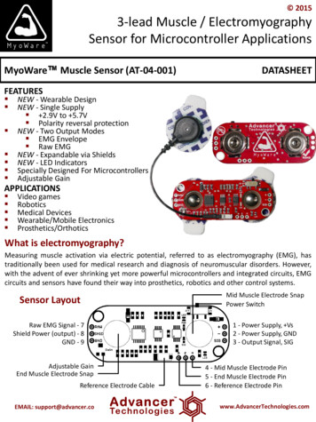
20153-lead Muscle / ElectromyographySensor for Microcontroller ApplicationsMyoWare Muscle Sensor (AT-04-001)DATASHEETFEATURES NEW - Wearable Design NEW - Single Supply 2.9V to 5.7V Polarity reversal protection NEW - Two Output Modes EMG Envelope Raw EMG NEW - Expandable via Shields NEW - LED Indicators Specially Designed For Microcontrollers Adjustable GainAPPLICATIONS Video games Robotics Medical Devices Wearable/Mobile Electronics Prosthetics/OrthoticsWhat is electromyography?Measuring muscle activation via electric potential, referred to as electromyography (EMG), hastraditionally been used for medical research and diagnosis of neuromuscular disorders. However,with the advent of ever shrinking yet more powerful microcontrollers and integrated circuits, EMGcircuits and sensors have found their way into prosthetics, robotics and other control systems.Sensor LayoutMid Muscle Electrode SnapPower SwitchRaw EMG Signal - 7Shield Power (output) - 8GND - 91 - Power Supply, Vs2 - Power Supply, GND3 - Output Signal, SIGAdjustable GainEnd Muscle Electrode SnapReference Electrode CableEMAIL: support@advancer.co4 - Mid Muscle Electrode Pin5 - End Muscle Electrode Pin6 - Reference Electrode Pinwww.AdvancerTechnologies.com
2015Setup Configurations (Arduino is shown but MyoWare is compatible with most development boards)RECOMMENDEDa) Battery powered with isolation via no direct external connectionsNote: Since no component isconnected to electrical grid,further isolation is notrequired. It is alsoacceptable to power theMCU with a battery via theUSB or barrel ports.Note: Isolation amplifier andbattery provide isolationbetween user and electricalgrid. IC models aresuggestions only.IsolationAmplifier(ISO124)EMAIL: support@advancer.co(Note: Arduino and batteries not included. Arduino setup is onlyan example; sensor will work with numerous other devices.)b) Battery powered sensor, Grid powered MCU with output isolationwww.AdvancerTechnologies.com
2015Setup Configurations (cont’d)c) Grid powered with power and output isolationNote: Isolation amplifier andpower isolator provideisolation between user andelectrical grid. IC models aresuggestions only.Power Isolator(R1SE-0505-R)IsolationAmplifier(ISO124)d) Grid powered. Warning: No isolation.Note: This configuration has noisolation. Usually safe but raresituations could create acurrent loop to the electricalgrid. Not suitable forcommercial applications.EMAIL: support@advancer.cowww.AdvancerTechnologies.com
2015Setup InstructionsNote: Not To ScaleExample Sensor Location for Bicep1)2)Thoroughly clean the intended area with soap to remove dirt and oilSnap electrodes to the sensor’s snap connectors(Note: While you can snap the sensor to the electrodes after they’ve been placed on the muscle, we do notrecommend doing so due to the possibility of excessive force being applied and bruising the skin.)3)4)Place the sensor on the desired musclea. After determining which muscle group you want to target (e.g. bicep, forearm,calf), clean the skin thoroughlyb. Place the sensor so one of the connected electrodes is in the middle of themuscle body. The other electrode should line up in the direction of the musclelengthc. Peel off the backs of the electrodes to expose the adhesive and apply them tothe skind. Place the reference electrode on a bony or nonadjacent muscular part of yourbody near the targeted muscleConnect to a development board (e.g. Arduino, RaspberryPi), microcontroller, or ADCa. See configurations previously shownEMAIL: support@advancer.cowww.AdvancerTechnologies.com
2015Why is electrode placement important?Raw EMG outputInnervation ZoneCorrect PlacementMidline of the muscle bellybetween an innervation zoneand a myotendon junctionMidline OffsetMyotendon JunctionPosition and orientation of the muscle sensor electrodes has a vast effect on the strength ofthe signal. The electrodes should be place in the middle of the muscle body and should bealigned with the orientation of the muscle fibers. Placing the sensor in other locations willreduce the strength and quality of the sensor’s signal due to a reduction of the number ofmotor units measured and interference attributed to crosstalk.EMAIL: support@advancer.cowww.AdvancerTechnologies.com
2015RAW EMG vs EMG EnvelopeOur Muscle Sensors are designed to be used directly with a microcontroller. Therefore, oursensors primary output is not a RAW EMG signal but rather an amplified, rectified, andintegrated signal (AKA the EMG’s envelope) that will work well with a microcontroller’sanalog-to-digital converter (ADC). This difference is illustrated below using arepresentative EMG signal. Note: Actual sensor output not shown.RAW EMG SignalRectified EMG SignalRectified & IntegratedEMG SignalReconfigure for Raw EMG OutputThis new version has the ability to output an amplified raw EMG signal.To output the raw EMG signal, simply connect the raw EMG signal pin to your measuringdevice instead of the SIG pin.Note: This output is centered about an offsetvoltage of Vs/2, see above. It is importantto ensure Vs is the max voltage of theMCU’s analog to digital converter. This willassure that you completely see both positiveand negative portions of the waveform.EMAIL: .com
2015This new version has embedded electrodesnaps right on the sensor board itself,replacing the need for a cable. However, ifthe on board snaps do not fit a user’sspecific application, an external cable canbe connected to the board through threethrough hole pads shown above.RefEndMiddleConnecting external electrode cablesMiddleConnect this pad to the cable leading to anelectrode placed in the middle of the muscle body.EndConnect this to the cable leading to an electrodeplaced adjacent to the middle electrode towardsthe end of the muscle body.RefConnect this to the reference electrode. Thereference electrode should be placed on anseparate section of the body, such as the bonyportion of the elbow or a nonadjacent muscleAdjusting the gainWe recommend for users to get their sensor setup working reliably prior to adjusting thegain. The default gain setting should be appropriate for most applications.To adjust the gain, locate the gain potentiometer in the lower left corner of the sensor(marked as “GAIN”). Using a Phillips screwdriver, turn the potentiometer counterclockwiseto increase the output gain; turn the potentiometer clockwise to reduce the gain.Note: In order to reduce the required voltage for thesensor, the redesign switch out a JFET amplifier for aCMOS amplifier. However CMOS amplifiers tend to haveslower recovery times when saturated. Therefore, weadvise users to adjust the gain such that the output signalwill not saturate the amplifier.EMAIL: support@advancer.cowww.AdvancerTechnologies.com
2015Electrical SpecificationsParameterMinTYPMaxSupply Voltage 2.9V 3.3V or 5V 5.7VAdjustable Gain Potentiometer0.01 Ω50 kΩ100 kΩOutput Signal VoltageEMG EnvelopeRaw EMG (centered about Vs/2)0V0V--- Vs VsInput Impedance--110 GΩ--Supply Current--9 mA14 mACommon Mode Rejection Ratio (CMRR)--110--Input Bias--1 pA--Dimensions2.06 (52.3)1.75 / (44.4)2 x 0.125” DIA. Thru Hole0.82(20.7)0.51(13.0)0.019(5.0)1.93 / (49.1)EMAIL: support@advancer.cowww.AdvancerTechnologies.com
3) Place the sensor on the desired muscle a. After determining which muscle group you want to target (e.g. bicep, forearm, calf), clean the skin thoroughly b. Place the sensor so one of the connected electrodes is in the middle of the muscle body. The other electrode should line up in the direction of the muscle