Transcription
RWANDASTANDARDDRS291Second edition2021-mm-ddMaximum road speed governors for motorvehicles — RequirementsICS 43.040.30Reference numberDRS 291: 2021 RSB 20211
DRS 291: 2021In order to match with technological development and to keep continuous progress in industries,standards are subject to periodic review. Users shall ascertain that they are in possession of the latestedition RSB 2021All rights reserved. Unless otherwise specified, no part of this publication may be reproduced or utilizedin any form or by any means, electronic or mechanical, including photocopying and microfilm, withoutprior written permission from RSB.Requests for permission to reproduce this document should be addressed to:Rwanda Standards BoardP.O Box 7099 Kigali-RwandaKK 15 Rd, 49Tel. 250 788303492Toll Free: 3250E-mail: info@rsb.gov.rwWebsite: www.rsb.gov.rwePortal: www.portal.rsb.gov.rw RSB 2021 - All rights reserved
ContentsForeword . 31Scope . 42Normative references . 43Terms and definitions . 444.14.24.3Requirements . 5Requirements for the system . 5Requirements for speed governors . 6Speed recording and storing device . urability and environmental performance . 8System durability . 8Time and temperature stability . 8Electrical power supply . 8Steady state voltage . 8Ripple . 8Reverse polarity . 8Transients . 8Stabilized speed . 9Input/output protection . 9Electromagnetic compatibility . 9Environmental protection . 106Marking . 10Annex A (normative) System durability test . 11Annex B (normative) Time and temperature stability test . 12Annex C (normative) Transient voltage test severity levels . 13Annex D (normative) Transient voltage test severity levels . 14D.1Chassis and cab mounted components . 14D.1.1 General . 14D.1.2 Resonance search . 14D.1.3 Endurance test at resonance frequency . 14D.2Engine mounted components . 14D.2.1 General . 14D.2.2 Resonance research . 15D.2.3 Endurance test at resonance ranges . 15 RSB 2021 - All rights reservedPage
DRS 291: 2021ForewordRwanda Standards are prepared by Technical Committees and approved by Rwanda Standards Board (RSB)Board of Directors in accordance with the procedures of RSB, in compliance with Annex 3 of the WTO/TBTagreement on the preparation, adoption and application of standards.The main task of technical committees is to prepare national standards. Final Draft Rwanda Standards adoptedby Technical committees are ratified by members of RSB Board of Directors for publication and gazettment asRwanda Standards.DRS 291 was prepared by Technical Committee RSB/TC 023, Road Vehicles.In the preparation of this standard, reference was made to the following standards:1) KS 2295-1: 2011, Maximum road speed governors for motor vehicles — Part 1: Performance andinstallation requirements2) KS 2295-2:2011, Maximum road speed governors for motor vehicles — Part 2: Specification for system andcomponent requirements3) IS 14382:1996, Automotive vehicles- Speed limiters — Specification for installed requirementsThe assistance derived from the above source is hereby acknowledged with thanks.This second edition cancels and replaces the first edition (RS 291: 2015), [clause(s) / subclause(s) / table(s) /figure(s) / annex(es)] of which has been technically revised.Committee membershipThe following organizations were represented on the Technical Committee on Title of TC (RSB/TC 023) in thepreparation of this standard.ATECARKENSRIN COMPANY LtdMOTA ENGILPASCAL Technology LtdPURE PRO LtdRwanda Polytechnic/Integrated Polytechnic Regional College Ngoma (IPRC Ngoma)Rwanda Polytechnic / Integrated Polytechnic Regional College Kigali (RP/IPRC Kigali)University of Rwanda/College of Science and Technology (UR-CST)VW Rwanda LtdRwanda Standards Board (RSB) – Secretariat RSB 2021 - All rights reserved
Maximum road speed governors for motor vehicles — Requirements1ScopeThis Draft Rwanda Standard specifies the requirements for the performance and installation of devices designedto control the speed and limit the maximum road speed of motor vehicles by control of engine power. It alsospecifies the requirements for the performance of systems and components designed to form part of a speedgovernor intended to limit the maximum road speed of motor vehicles by control of engine power2Normative referencesThe following documents are referred to in the text in such a way that some or all of their content constitutesrequirements of this document. For dated references, only the edition cited applies. For undated references, thelatest edition of the referenced document (including any amendments) applies.IEC 60068-2-1, Environmental testing – Part 2-1: Tests – Test A: Cold stabilityIEC 60068-2-2, Environmental testing – Part 2-2: Test – Test B: Dry heat stabilityIEC 60068-2-38, Environmental testing – Part 2-38: – Test – Test Z/AD: Composite temperature/humidity cyclictest stabilityRS ISO 7637-1, Road vehicles — Electrical disturbances from conduction and coupling — Part 1: Definitionsand general considerationsISO 7637-2, Road vehicles — Electrical disturbances from conduction and coupling — Part 2: Electricaltransient conduction along supply lines only3Terms and definitionsFor the purposes of this standard, the following terms and definitions apply3.1enginesource (or sources) of the vehicle’s motive power3.2qualified agentauthorized motor vehicle inspector or traffic police officer3.3inspection devicepiece of equipment that has been designed to test all circuitry and shall be able to detect any interference withthe system3.4speed governordevice designed to limit the maximum speed of an automotive vehicle by controlling the engine power of thatvehicle. RSB 2021 - All rights reserved
DRS 291: 20213.5set speedintended mean vehicle speed when operating in a stabilized condition. It is marked on the vehicle and used forcalibration purposes3.6judderingaction of shaking rapidly during the retardation process3.7permanent damagedamage sustained by a component or system which renders it inoperative. For the purpose of this definition therupture of a fuse or the operation of other user serviceable circuit protection devices is not taken to be permanentdamage3.8normal functionfunctioning in accordance with the requirements of this standard3.9failure to functionfunctioning outside the requirements of this standard but not suffering any permanent damage3.10nominal voltagevoltage of 12 V 1 V d.c or 24 V 2 V d.c3.11Vmaxmaximum speed declared by the supplier of the speed limiter at which it is set to meet the requirements of thisstandard3.12Vminminimum speed declared by the supplier of the speed limiter at which it is set to meet the requirements of thisstandard.4Requirements4.1 Requirements for the system4.1.1 The systems shall be “failsafe” in such a way that if the plug to the electronic controller is removed, poweris disconnected or if the speed signal and/or wire is disconnected the vehicle shall automatically, default to alimp mode or the engine shall stall or return to idle and thus shall not be able to be driven in excess of 20 kmper hour.4.1.2 The system shall be able to be verified, authenticated and tested by an authorized agent by means of anelectronic device, which can be plugged into a receiver installed in a convenient position on the vehicle, whilstthe vehicle is on the road. This device should test all circuitry and shall be able to detect any interference withthe system. RSB 2021 - All rights reserved
4.1.3 The equipment shall monitor the road speed of the vehicle by being integrated to the electronicspeedometer signal input, where possible or by the installation of an electro-mechanical speed sensor installedonto the speedometer cable take off at the gearbox or by use of other speed signal method as may be specifiedby manufacturer.4.1.4 All cable or harness connectors in the speedometer circuit shall be wired and sealed for certificationpurposes.4.1.5 The equipment shall pre-warn the driver, by way of a high frequency buzzer, that the set speed is beingreached. This warning shall occur at 5 % prior to the set speed and shall continue buzzing once the set speedis achieved4.1.6 When the set speed is reached, the speed governor shall temporarily cause the engine to lose power.Engine power shall be reinstated at a speed not less than the pre-warning switch point, which is 5 % below theset speed4.1.7 A second (critical) road speed governor set point shall activate a retarder device (where legislated) whenthis set point is reached. This set point shall be no more than 5 % above the standard set point and shall,automatically, activate the retarder to ensure that the vehicle cannot exceed the preset limit.4.1.8 The speed governor shall be set in such a way that it shall be tamper proof with (adjust speed) and easyto detect tampering.4.1.9 All road speed governors systems shall be checked for accuracy and functionality, at least once per year,at the time of the motor vehicle inspection. The maximum deviation from the set speed limit shall be not morethan 3.3 %.4.1.10 Speed shall be sensed to an accuracy of 3.3 % of actual vehicle speed, with the range Vmin to Vmax4.1.11 The road speed governor system shall be equipped with a system which shall accept an external devicefor testing the speed governor and verifying its functionality.4.1.12 the speed limiting device shall be calibrated to a set speed complying with the regulatory requirements.4.1.13 the speed governor shall be type approved by the competent authority. The speed governors that havebeen type approved shall not be permitted to modify or redesign unless the validity of type approval has beenrevalidated.4.1.14 the manufacturer of the speed governor shall provide manual describing installation, checking andcalibration procedures. After installation it should be possible to check the set speed while the vehicle isstationary.4.1.15 The speed governor shall be suitable for installation in the vehicle and shall be installed in accordancewith the installation procedures of the manufacturer. The installation shall be done by technicians approved bycompetent authority.4.2 Requirements for speed governors4.2.1The speed governors shall meet the following requirements:a) no effect on the normal operation of vehicle1) road speed governor shall allow normal acceleration and full engine power up to the set maximumspeed limit when the limitation function comes to play;2) speed limitation function or road speed governor shall not interfere with the brake system of thevehicle; RSB 2021 - All rights reserved
DRS 291: 20213) speed limiting function shall be performed progressively in such a manner that excessive judderingor discomfort is not caused;4) speed limiting function shall not cause engine back firing;5) speed limitation function or the road speed governor shall not cause uncontrolled engine power;6) no malfunction or tempering shall result in increase in engine power above that demanded by theposition of the drivers accelerator;7) speed limitation function shall be obtained once the vehicle speed reaches the set maximum speedregardless of the position action on the accelerator a driver may apply;8) speed limitation function shall be independent of the condition or soundness of the speedometerb) compatibility with environmental conditions1)speed governor shall be so designed, constructed and assembled so as to resist vibrations, corrosion,dust, humidity and petrochemical emissions;2) speed limitation function, or the speed limitation device shall operate satisfactorily withoutunacceptable electromagnetic disturbance from anything in its environment; and3) road speed governor shall be resistant to reverse polarity connections.c) susceptibility to tampering1)limitation threshold shall not, in any case be capable of being increased or removed temporarily onvehicles where the speed limitation device has been fitted;2)speed limitation function, the road speed governor and the connections necessary for its operationshall be capable of being protected from any unauthorized adjustments or the interruptions of its energysupply by the attachment of sealing devices and/or the need to use special tools;3)all components necessary for the full function of the limiter shall be energized whenever the vehicle isbeing driven; and4)road speed governor shall be designed and constructed in such a way that it can be fitted in a placenot easily accessible to unauthorized people.d) functionality inspection devices (policing units)4.2.2 The road speed governor shall have in built features that allow functionality checks and shall havespecial inspection devices for this purpose to facilitate the checking when the vehicle is not in motion or thespeed governor is disconnected.NOTEAn example of such features is the Global Positioning System GPS.4.3 Speed recording and storing device4.3.1 The speed limiting system shall incorporate a mechanism for recording the speed of the vehicle whichspeed shall be date (day, month and year) and time related, which shall store the data in a non erasable memoryand when power supply disconnected shall remain.4.3.2 The speed shall be recorded in km/h at not more than 5 sec interval4.3.3 The stored data shall be retrievable and easy to export in a format which is acceptable and type approvedby the competent authority. RSB 2021 - All rights reserved
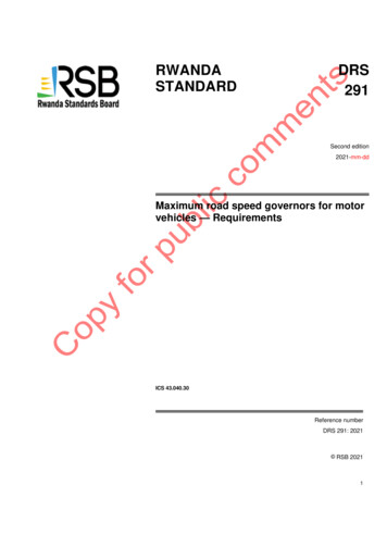
4.3.4 The file of at least within past 72 h driving time data shall be read only and stored in accordance with 4.3.3.5Durability and environmental performance5.1 System durabilityThe system, in condition equivalent to new, shall be tested in accordance with Annex A and, after completionof test, shall comply with the manufacturer’s specification.5.2 Time and temperature stabilityThe system, in condition equivalent to new, shall be tested in accordance with Annex B. During the proceduresin clause B.1 to B.7 and B.9 the sensed speed shall not differ from the set speed by more than 3.3 %.5.35.3.1Electrical power supplySteady state voltageThe system shall function normally when connected to a power supply in the range (12/24 V) d.c.5.3.2RippleNormal operation of the system shall not be affected by regular or irregular variations in voltage about theprevailing supply level (excluding transients) not exceeding 3 V ( 2 V d.c.) peak to peak in the range 10 Hz to10 000 Hz5.3.3Reverse polarityThe system shall be reverse polarity protector.5.3.4Transients5.3.4.1 After the set speed is achieved (see fig 1), the following conditions shall be fulfilled:a) the sensed speed shall not exceed the set speed by more than 5 %;b) the rate of change of sensed speed shall not exceed 0.5 m/s2; andc) the stabilized speed conditions specified in 5.3.5 shall be attained within 10 sec of first reaching the set speed. RSB 2021 - All rights reserved
DRS 291: 2021Figure 1 — Allowed tolerances of governor response characteristic5.3.4.2 Tests for immunity to transients shall be conducted in accordance with ISO 7637-1 for 12 V systemsand ISO 7637-2 for 24 V systems. Transient voltage test severity levels are given in Annex C.5.3.5Stabilized speedWhen stable speed control has been achieved (see fig 1), the following conditions shall be fulfilled:a) the sensed speed shall not differ from the set speed by more than 3.3 %; andb)the rate of change of sensed speed shall not exceed 0.2 m/s 2.5.3.6Input/output protectionEach output/input in turn shall withstand connection to earth for 1 min duration, without permanent damage,with the system operating and shall return to normal function when the connection is removed.5.3.75.3.7.1Electromagnetic compatibilitySupply line interfaceWhen tested in accordance with relevant approved standards, the system shall operate correctly with 3 V r.m.s.interference, at any frequency in the range 1 MHz to 150 MHz, superimposed on either battery supply line withrespect to a reference ground plane.5.3.7.2Electromagnetic emissionsWhen tested in accordance with relevant approved standards and with the values of electromagnetic emissionsmeasured on the output port of a 50-W line impedance stabilizing network, the system under test shall not causeinterference in the supply line exceeding the value shown in Table 1. RSB 2021 - All rights reserved
Table 1 — Maximum supply line interference levelsS/N5.3.7.3Frequency band MHzMeasured level relative to 1 microvoltin 50 W ( dB)10.15 to 0.2970 level20.30 to 4.9060 level35.00 to 2950 level430 to 108Slope 50 to 30Radio Frequency field susceptibilityWhen tested in accordance with relevant approved standards, the system shall function normally whensubjected to a Radio Frequency field of 140 dB above 1 µV/m (10 V/m) over a frequency range of 1 MHz to 220MHz.5.4 Environmental protectionFor environmental protection, components of the system shall be subjected to tests in accordance with IEC60068-2-1; IEC 60068-2-2 and 60068-2-38, after each of which they shall continue to function normally.6MarkingEach control unit and actual shall be marked with the following in one of the official languages used in Rwanda:a) name and/or trade mark of the manufacturer;b) model number;c) serial number;d) country of origin;e) set speed, expressed in km/h, at which the vehicle is calibrated; andf) calibration date (day, month and year). RSB 2021 - All rights reserved
DRS 291: 2021Annex A(normative)System durability testA.1 Connect the components of a system in accordance with the manufacturer’s instructions and wherenecessary adjust to simulate maximum load/travel conditions (worst case). Connect a 24 V (12 V) battery withthe charge maintained at 28 (14) 1 V d.c.A.2Activate the system through the following test cycle:a) drive to a full range travel (t1);b) reverse to zero output (t2)c) drive to mean position (t3)d) control at mean output for 5 (t1 t2 t3) and e) reverse to zero out; where t is the time required to completeeach individual operation.A.3Repeat this test cycle for 250 000 cycles RSB 2021 - All rights reserved
Annex B(normative)Time and temperature stability testB.1 Connect up the system in a test chamber at 18 0C 2 0C to a supply of 28 (14) 1 V d.c., complete withsimulation of components of the loop between the throttle actuator and speed (i.e. engine and transmission)outside of the test chamber.B.2 Set simulated throttle demand to maximum.B.3 Adjust the set speed of the system where appropriate.B.4 Activate the system and the recorder. Throughout the test, B.5 to B.7, record the maximum deviation fromthe set speed.B.5 Allow the system to operate for 10 h.B.6 Reduce the test chamber temperature to 0 0C 2 0C. After the temperature of the test chamber hasstabilized, operate the systems for further 30 min.B.7 Increase the test chamber temperature to 60 0C 2 0C. After the temperature of the test chamber hasstabilized, operate the system for further 30 min.B.8 Increase the test chamber temperature to 80 0C 2 0C. After the temperature of the test chamber hasstabilized, operate the system for a further 30 min. The system shall continue to function but accuracy may bedegraded.B.9 Reduce the test chamber temperature to 60 0C 2 0C. After the temperature of the test chamber hasstabilized, operate the system for further 30 min. Record the maximum deviation from the set speed. RSB 2021 - All rights reserved
DRS 291: 2021Annex C(normative)Transient voltage test severity levelsTable C.1 — Transient voltage test severity levelsTest pulseTest levelFunctional statusNumber of pulses ortest time1-150 (-75)C50002 150 ( 75)C50003) a-150 (-75)A1h3) b 150 ( 75)A1h4-12 (-6)C5 pulses5 180 ( 80)C1 pulseNOTE These values are for use in conjunction with ISO 7637-1 or ISO 7637-2NOTE A is normal function and C is fail but recover RSB 2021 - All rights reservedRemarks1 min between each
Annex D(normative)Transient voltage test severity levelsD.1 Chassis and cab mounted componentsD.1.1 GeneralSubject the component to be tested, mounted on its normal mount, complete with its ancillary components, toresonance search in all three planes using a sinusoidal wave form under the conditions given in D.1.2 followedby an endurance test under the conditions given in D.1.3.D.1.2 Resonance search Frequency range 10 Hz to 250 Hz Input Sweep time Duration2 gn2 minLong enough to establish resonant frequencyD.1.3 Endurance test at resonance frequencyD.1.3.1 If there is resonance, carry out a broad sweep endurance test under the following conditions: Frequency range 3 dB below peak for each resonance Input2 gn Sweep time1 Hz/s Duration7.2 hD.1.3.2 if there is no resonance, carry out a broad sweep endurance test under the following conditions: Frequency range10 Hz to 250 Hz Input2 gn Sweep rate Duration4 Hz/s30 h/planeD.2 Engine mounted componentsD.2.1 GeneralSubject the component to be tested, mounted on its normal mount, complete with it ancillary components to aresonance search in all three planes using a sinusoidal wave form under the conditions given in D.2.2 followedby an endurance test under the conditions given in D.2.3 RSB 2021 - All rights reserved
DRS 291: 2021D.2.2 Resonance research Frequency range 40 Hz to 2 000 Hz Input6 gn Sweep time2 min DurationLong enough to establish resonant frequenciesD.2.3 Endurance test at resonance rangesFrequency range 3 dB below peak for each resonance in the ranges 40 Hz to 200 Hz and 200 Hz to 2 000 Hz Input12gn6gn Sweep time2 Hz/s5 Hz/s Duration 107 reversals at resonant frequency If there is no resonance, carry out a broad sweep endurance test under the following conditions: Frequency range Input Sweep rate2 Hz/s Duration10 h/plane RSB 2021 - All rights reserved40 Hz to 200 Hz12gn200 Hz to 2 000 Hz6gn5 Hz/s10 h/plane
BibliographyRS 291: 2015, Maximum road speed governors for motor vehicles — Requirements RSB 2021 - All rights reserved
DRS 291: 2021Price based on nnn pages RSB 2021 - All rights reserved
4.1.15 The speed governor shall be suitable for installation in the vehicle and shall be installed in accordance with the installation procedures of the manufacturer. The installation shall be done by technicians approved by competent authority. 4.2 Requirements for speed governors 4.2.1 The speed governors shall meet the following requirements: