Transcription
Development and Demonstration of aNew Generation High-Efficiency 1-10 kWStationary PEM Fuel Cell Power SystemDurai Swamy, Ph.D.Intelligent EnergyJune 12th, 2008Project FC39This presentation does not contain any proprietary, confidential, or otherwise restricted information
OverviewBarriersTargetsTimeline Start:July 2007 End:July 2010 25% complete by 4/08Budget 4.4 million budget 50% DOE cost share 322K received FY07 450K projected for FY08Electrical Eff.Overall Eff.ProjectDOE 201140%40% 70%80%Durability40,000 hrs 40,000 hrsCapital Cost 400 / kW 750 / kWPartners Intelligent Energy, Inc. (lead) Intelligent Energy, Ltd. University of South Carolina California State PolytechnicUniversity, Pomona Sandia National Labs
ObjectivesDevelop and demonstrate a PEM fuel cell based stationarypower system that provides foundation for commercial, massproduced units that address identified technical barriers Technical objectives 40% electrical efficiency (fuel to electric energyconversion) 70% overall efficiency (fuel to electric energy usablewaste heat energy conversion) Potential for 40,000 hour life Potential for 450/kW Topic 7A – International Partnership for a HydrogenEconomy (IPHE) Engage international partners Demonstration phase in an IPHE country other than USA
MilestonesMonth/YearMilestone or Go/No-Go DecisionJuly 2007Contract signed and project launchedJanuary 2008Milestone: Evaluation of adsorbent materials foruse in adsorption enhanced reformercompleted; initial tests with high pressuremembrane reformer completedJuly 2008Go/No-Go Decision: Validation of hydrogengeneration and fuel cell performanceimprovements demonstrating the viability ofachieving a 40% electrical efficiency for thesystem will be complete. A Go decision will befollowed by proceeding to development andtesting of a prototype PEMFC power system.
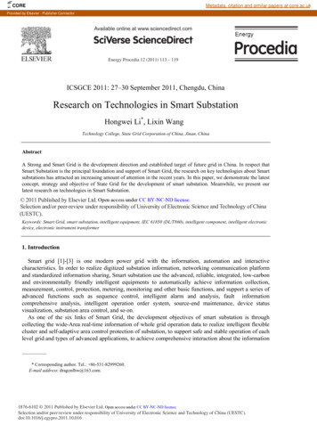
ApproachOpen architecture – high purity hydrogen interface between fuelcell, fuel processorAverage Fuel Cell Voltage, V/cell0.90CHP B0.850.80Design pointsabove lineexceed 40%efficiency15% Parasatic Power10% Parasatic Power5% Parasatic Power0.750.700.65CHP ACHP C0.60Designpointsbelow the60%line 65% 70% 75% 80% 85% 90%do not achieveH2 Generation Eff, %40% efficiencyNote: H2 generation efficiency isfor high purity hydrogen notreformate. A typical 85% efficientreformate and 75% anode fuelutilization would imply a 64% H2generation efficiency. Increase cellvoltages Increasehydrogengenerationthermalefficiency Decreaseparasitic loads
ApproachFuel cell stack and system Improved flow field design Fluid flow modeling Advanced MEA design Diffuser optimized for watermanagement Advanced bipolar platematerials Reduced air pressurerequirements Pressed plate architecture toaddress cost Optimized air delivery design Optimized power managementdesign & configurationHydrogen generationEthanol reforming - Twoplatforms in development MesoFuel advanced membranereactor ( 2 kWe) Increase reactor pressure Thermal integrationimprovements Hestia with rapid cycle PSA ( 2 kWe) With 100mV fuel cell voltageimprovement, efficiency targetcan be reached with optimizationof current Hestia design With 20mV fuel cell voltageimprovement, efficiency targetcan be reached with integration ofCO2 adsorption (AER) into Hestiaprocess
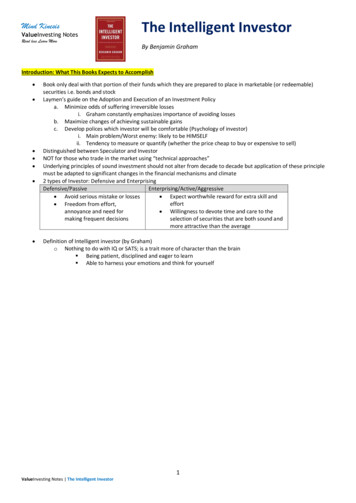
Technical 456Improvements show cumulativeeffects of new MEA, coolingarchitecture and diffuser material0.30.2Combined technology 00.600.70Current Density/A cm-20.800.901.0042281401.10Cell Power/WCell Voltage/VPEMFC – single cell performance improvements
Technical AccomplishmentsPEMFC – reduced system parasitic loadsHigh efficiency DC/DC converter development High voltage converter for compressor operation Low voltage converter for battery charging andauxiliaries Data indicate efficiencies of 95 % may be possibleCurrent work and next steps Test the converter in a system Test self-start operation
Technical AccomplishmentsPEMFC – forecast fuel cell system performance improvement70%57.4% efficient at 6kWe (baseline 50%)Gross Electrical Efficiency60%efficiency LHV H250%Net Electrical Efficiency40%30%Data show potential systemefficiencies based on: Improved fuel cell performance Reduced compressor power Unregulated DC voltage output20%10%Baseline SystemBaseline StackJan 08 SystemJan 08 StackApril 08 SystemApril 08 Stack0%02468net output power/kW1012
Technical AccomplishmentsHestia reformer - new reactor design Designed for ease of manufacture, assembly Reduced pressure drop across combustor/flue gas path Enhanced thermal integration Streamlined balance of plant Increased operating pressure / H2 recovery Status Fabrication, assembly completed fall 2007 Testing initiated December 2007 Initial ethanol tests performed January 2008 Preparing for next phases of tests April 2008
Technical AccomplishmentsHestia reformer – initial results New reformerreactor has beentested as standalonesystem, usingsimulated PSA offgas as heat source Results to left showexpected H2generation efficiencybbasedd on reformerftest results potential PSArecoveries
Technical AccomplishmentsMeso reformer – performance mapping of single module completedMetricTargetStatus(4/15/08)H2 purity 99.9% 99.9%Thermalefficiency 70%65 - 67%H2 production,slpm5-6(10 module)0.6 @ 65 67% efficiency(single module)H2 flux,sscm/cm215-2015-17TPfeedPprodS/C 575 – 640 C70 – 175 psig5 psig – 500 mbar4.5
Technical AccomplishmentsMeso reformer – summary of flux and efficiency Purity 99.99% Also demonstrated methane reforming Stable operation achieved
Technical AccomplishmentsAER – dynamic model for AER process steps (U South Carolina)PSA model adapted to PSA model adapted toinclude reforming reactionsModel has informed experimental apparatusdesigns Bed sizing Cycle times Temperatures CO2 breakthrough Purge gas requirementsStatus: Calibrating model with experimentalresults. Model breakthrough times are similarto test data– include reforming reactions– Model has informed experimental apparatusdesigns Bed sizing Cycle times Temperatures CO2 breakthrough Purge gas requirements– Status: Calibrating model with experimentalresults. Model breakthrough times are similarto test data1.0Volume fraction0.7CH4N2H2COCO2H2 SteamAER0.8N2 Purge0.90.60.5All gasesbut CO2getinstantlypurged outof the bed0.40.30.2Methanationwith H2 andsorbed CO20.10.00306090120150180210240TOS [min]TOS, min
Technical AccomplishmentsAER –experimental proof of conceptReformate Composition of 33 wt.% SR-1 / Pural MG70 with 20% K2CO3100N2EtOH H2ON2EtOH H2OH2 H2OH2 H2OH2 H2ON2H2 H2OH2CH4COCO280Concentration [vol.%]N2EtOH H2O60402000306090120150180210240TOS [min]The above chart demonstrates four consecutiveAER cycles successfully demonstrated onsmall reactor with ethanol‐water mixture(S/C 6, 70 psig) Chart shows consecutive cycles with Ethanolon larger reactor (S:C 4.5) Table below is total cycles on larger reactorthrough May 2008 e
Technical AccomplishmentsAER – full scale experimental results with integrated combustor Currently evaluating cycletiming, temperatureprofiles, heat balance Reactor and test standspecifications: Natural gas or ethanol 1 to 5 kWe Regenerate with nitrogen,steam or other All heat provided bycombustion Measure H2 productionenhancement as well as CO2breakthrough in bed
Technical AccomplishmentsAER – novel adsorbent materials (Cal Poly Pomona) Amorphous magnesium oxide (MgO)ambigel and xerogel materials Significant potential for increasedadsorption capacity Status: Several batches synthesized andcurrently being analyzed by IE Further batches plannedSEM of monolithic MgO aerogel(left) and xerogel (right)
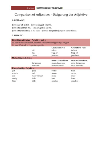
Technical AccomplishmentsSystem level performance assessment (Sandia) Collaboration with Sandia National Labs to assess potentialperformance of possible system architectures Part of Sandia’s contribution to IEA-HIA Task 18 Status (4/15/08): Collaboration launched in March 2008 System model adapted to capture IE’sapproachFuelH2O Initial results show 35% fuel-toAirelectric efficiency based on historicalWeHestia reformer data, new fuel celldata and parasitic power losses Next steps Consider other system architectures Continue to update models withexperimental data Form basis for go/no-go in July 2008SyngasRetentateReformerSeparation(PSA)H2FlueKO waterH2StorageFlueHeatRecoveryHeat LoadQFCPowerManageBatte-LoadWeH2Air
Future WorkFY08 Go/No-Go (July 2008): Determine system architectureleading to reaching technical objectives Go decision will be followed by proceeding to developmentand testing of a prototype PEMFC power systemFY09 Milestone (January 2009): Complete engineeringdesign of integrated power system Milestone followed by in-house system testing Go/No-Go (July 2009): Validation of the prototypepower system’s ability to meet performance targetswill be complete Go decision will be followed with continuing to the fielddemonstration of this system
SummarySummary of technical progress highlightsSystemBaselineStatus(4/15/08)Fuel ophisticatedmechanicaldesignDesign formanufacture andassemblyMesohydrogengeneratorefficiency50%65 – 67%AdsorptionenhancedreformerConcept onpaperExperimentalproof of concept Approach: Developportfolio of technologies inProject Year 1 (Jul-07 – Jul08) to determine bestarchitecture for meetingDOE objectives forstationary fuel cell power Partners IE in US (lead) & UK U of South Carolina Cal Poly Pomona Sandia Nationa Labs Future work: Down-selecttechnologies then engineer,test and demonstrate newgeneration PEMFC powersystem
Collaboration with Sandia National Labs to assess potential performance of possible system architectures Part of Sandia's contribution to IEA-HIA Task 18 e-Load Reformer Separation (PSA) Batt Power Manage FC Heat Recovery H2 Storage Heat Load Retentate Syngas Fuel H2O Air Q Air H2 H2 W e W e Flue KO water Flue Status (4/15/08):