Transcription
C O N T R O L SM A N U A LTouch Pilot Control30XA/XAS/XB/XBP/XW30XA-ZE/XW-ZEAquaForce PUREtec with R-1234ze(E)Original document
CONTENTS1 - SAFETY CONSIDERATIONS. 51.1 - General description. 51.2 - Safety precautions. 52 - CONTROLLER OVERVIEW. 52.1 - General description. 52.2 - Abbreviations. 53 - HARDWARE DESCRIPTION. 63.1 - General description. 63.2 - Electrical box. 63.3 - Connections of the main controller. 63.4 - Power supply to boards. 63.5 - Light emitting diodes on boards. 63.6 - Pressure sensors. 73.7 - Temperature sensors. 73.8 - Actuators. 73.9 - Connections at the user terminal block. 84 - TOUCH PILOT CONTROL INTERFACE. 94.1 - General description. 94.2 - Screens overview. 94.3 - Welcome Screen. 94.4 - Touch Pilot synoptic screen. 94.5 - Start/Stop screen. 104.6 - User Login screen. 104.7 - Language list selection. 114.8 - Main menu. 114.9 - Configuration menu. 124.10 - Override screen. 124.11 - Schedule screen. 125 - WEB CONNECTION. 135.1 - Web interface access. 135.2 - Web browser configuration. 135.3 - Technical documentation access. 136 - TOUCH PILOT INTERFACE DETAILS. 146.1 - Menu structure. 146.2 - Detailed menu description. 156.3 - Alarms menu . 226.4 - Configuration menu. 237 - TOUCH PILOT CONTROL OPERATION. 277.1 - Start/Stop control . 277.2 - Unit stop function. 277.3 - Heating/Cooling selection. 277.4 - Pumps control. 287.5 - Condenser water pump control. 287.6 - Control point. 297.7 - Capacity limitation. 307.8 - Current limitation. 307.9 - Capacity control. 307.10 - Night mode. 317.11 - Head pressure control. 317.12 - Circuit lead/lag selection (multi-circuit units). 317.13 - Compressor loading sequence (multi-circuit units). 317.14 - Circuit capacity loading sequence. 317.15 - Energy management module. 337.16 - Master/slave assembly. 337.17 - Heat reclaim option (30XA/30XB). 337.18 - Variable speed fans (option 17). 337.19 - Evaporator heater option (30XA/30XB). 337.20 - Free cooling option (30XA/30XB). 347.21 - Dry Cooler Free Cooling (30XB). 347.22 - Dry cooler option (30XW). 347.23 - Hydronic kit option (30XA/30XB). 347.24 - 30XA-ZE and 30XW-ZE units (HFO). 347.25 - High condensing temperature option (30XW). 347.26 - Maximum condenser leaving water temperature option (30XW). 347.27 - Time schedule function. 357.28 - Black box function. 357.29 - Trending. 352
CONTENTS8 - DIAGNOSTICS – TROUBLESHOOTING. 368.1 - E-mail notifications. 368.2 - Displaying alarms. 368.3 - Current alarms. 368.4 - Resetting alarms. 368.5 - Alarm history. 368.6 - Alarm codes. 37The cover photos are solely for illustration and forms no part of any offer for sale or any sale contract. The manufacturer reserves theright to change the design at any time without notice.3
PREFACEThe goal of this document is to give a broad overview of the mainfunctions of the Touch Pilot system used to control: 30XAS single-circuit air-cooled chillers, 30XA dual-circuit and triple-circuit air-cooled chillers, 30XB dual-circuit air-cooled chillers with fixed-speed fan controland 30XBP dual-circuit air-cooled chillers with variable-speedfan control,IMPORTANT: All screenshots of the interface provided in thismanual include text in English. After changing the languageof the system, all labels will be displayed in the languageselected by the user.Please read all instructions prior to proceedingwith any work. Pay attention to all safety warnings. 30XW single-circuit and dual-circuit water-cooled chillers, units that come with R-1234ze refrigerant (30XA-ZE air-cooledand 30XW-ZE water-cooled chillers).Instructions in this manual are given as a guide to good practicein the installation, start-up and operation of the control system.This document does not contain full service procedures for thecorrect operation of the equipment. The support of a qualifiedCarrier Service Engineer is strongly recommended to ensureoptimal operation of the equipment as well as the optimization ofall available functionalities.Note that this document may refer to optional components andcertain functions, options or accessories may not be available forthe specific unit. The cover images are solely for illustration andform no part of any offer for sale or any sale contract.4The information provided herein is solely for the purpose ofallowing customers to operate and service Carrier-manufacturedequipment and it is not to be reproduced, modified or used for anyother purpose without the prior consent of Carrier Corporation.
1 - SAFETY CONSIDERATIONS1.1 - General description1.2 - Safety precautionsInstallation, start-up and servicing of equipment can be hazardousif certain factors particular to the installation are not considered:operating pressures, electrical components, voltages and theinstallation site (elevated plinths and built-up structures).Only personnel qualified in accordance with IEC (InternationalElectrotechnical Commission) recommendations may be permittedaccess to electrical components. It is particularly recommendedthat all sources of electricity to the unit should be shut off beforeany work is begun. Shut off the main power supply at the maincircuit breaker or isolator.Only qualified installation engineers and fully trained techniciansare authorised to install and start the equipment. All instructionsand recommendations provided in the service guide, installationand operation manuals, as well as on tags and labels fixed to theequipment, components and other accompanying parts suppliedseparately, must be read, understood and followed. Failure tocomply with the instructions provided by the manufacturer mayresult in injury or product damage. Apply all safety standards and practices. Wear safety glasses and gloves. Use the proper tools to move heavy objects. Move units carefully and set them down gently.CAUTION: The equipment uses and emits electromagneticsignals. Tests have shown that the equipment conforms toall applicable codes with respect to electromagneticcompatibility.RISK OF ELECTROCUTION: Even when the main circuitbreaker or isolator is switched off, specific circuits may stillbe energised as they may be connected to a separate powersource.RISK OF BURNS: Electrical currents may cause componentsto get hot. Handle power cable, electrical cables and conduits,terminal box covers and motor frames with great care.IMPORTANT: Some specific safety precautions should betaken in case of HFO units.For more information about handling the equipment safely,please refer to the IOM Unit documentation (Installation,Operation and Maintenance instructions).2 - CONTROLLER OVERVIEW2.1 - General description2.2 - AbbreviationsThe Touch Pilot system controls the start-up of the compressorsneeded to maintain the desired heat exchanger entering andleaving water temperature. The controller manages the operationof the fans in order to maintain the correct condensing pressurein each circuit. Touch Pilot constantly monitors safety devices thatprotect the unit against failure and guarantee its optimalfunctioning.In this manual, the refrigeration circuits are called circuit A, circuit Band circuit C.The control system can operate in three independent modes: Local mode: The unit is controlled by commands from the userinterface. Remote mode: The unit is controlled by dry contacts. Network mode: The unit is controlled by network commands(CCN or BACnet). Data communication cable is used to connectthe unit to the CCN communication bus.The operating mode can be selected with the Start/Stop button(see also section 4.5). When the Touch Pilot system operatesautonomously (Local or Remote), it retains all of its controlcapabilities but does not offer any of the features of the Network.The Network emergency stop command stops the unit regardlessof its active operating type.CCNCarrier Comfort NetworkDCFCDry Cooler Free CoolingEMMEnergy Management ModuleEXVElectronic Expansion ValveLEDLight Emitting DiodeLENSensor Bus (internal communication bus linkingthe basic board to slave boards)OATOutdoor Air TemperatureNetwork modeOperating type: NetworkLocal-OffOperating type: Local OffLocal-OnOperating type: Local On modeLocal-ScheduleOperating type: Local On following a time scheduleMaster modeOperating type: master unit(master/slave assembly)Remote modeOperating type: by remote contactsVFDVariable Frequency Drive5
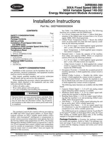
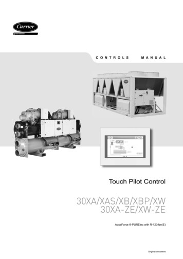
3 - HARDWARE DESCRIPTION3.1 - General description3.4 - Power supply to boardsEach circuit is by default fitted with one SIOB board used tomanage all inputs and outputs of the controller.All boards are supplied from a common 24 VAC supply referredto earth.TCPM board is used to control the operation of screw compressorsand AUX1 board is used for fans control (one AUX1 per each circuit).Please note that the first AUX1 board may also include the outputused to control the customer variable speed pump for single-circuitunits (see also section 7.4.3).CAUTION: Maintain correct polarity when connectingthe power supply to the boards, otherwise the boards maybe damaged.Options such as energy management, heat reclaim, free coolingrequire additional SIOB boards to be installed. Additionally, chillersfitted with a dry cooler have one extra AUX1 board used to controlthe optional dry cooler (the board included in the dry cooler).NOTE: There are two types of dry coolers available, i.e.dry cooler (condenser) used for 30XW water-cooled units andfree cooling dry cooler for 30XB air-cooled units.All boards communicate via an internal LEN bus. The main boardcontinuously monitors the information received from variouspressure and temperature probes and accordingly starts theprogram that controls the unit.The unit is equipped with the Touch Pilot user interface(5-inch colour LCD touch screen).3.2 - Electrical boxIn the event of a power supply interrupt, the unit restartsautomatically without the need for an external command. However,any faults active when the supply is interrupted are saved and mayin certain cases prevent a given circuit or the unit from restarting.3.5 - Light emitting diodes on boardsAll boards continuously check and indicate the proper operationof their electronic circuits. A light emitting diode (LED) lights oneach board when it is operating properly. The red LED flashing for a two-second period on the SIOBboard indicates correct operation. A different rate indicates aboard or a software failure. The green LED flashes continuously on all boards to show thatthe board is communicating correctly over its internal bus. If thegreen LED is not flashing, this indicates a LEN bus wiringproblem.The electrical box includes all boards controlling the unit and theuser interface.3.3 - Connections of the main controllerConnections are located on the bottom side of the main controller.(1)Legend1. USB connector2. Ethernet connector3. CCN connector4. LEN connector5. Power supply connector (24 VAC)6(2)(3)(4)(5)
3 - HARDWARE DESCRIPTION3.6 - Pressure sensors3.8 - ActuatorsTwo types of electronic sensors (high and low pressure) are usedto measure various pressures in each circuit. Evaporator pumpsThe controller can regulate one or two evaporator pumps andtakes care of the automatic changeover between these pumps(see also section 7.4).These electronic sensors deliver 0 to 5 VDC. The sensors areconnected to the SIOB board. Discharge pressure sensors (high pressure type)These sensors measure the discharge pressure in each circuit.They are used to control head pressure or high pressure loadshedding. Discharge pressure sensors are mounted on thedischarge line piping of each circuit. Suction pressure sensors (low pressure type)These sensors measure the suction pressure in each circuit.They are used for EXV control. Suction pressure sensors arelocated on the suction piping of each circuit. Oil pressure sensors (high pressure type)These sensors measure the oil pressure of each compressor.Oil pressure sensors are located at the oil port of thecompressor. The economizer pressure is subtracted from thisvalue to arrive at the differential oil pressure. Economizer pressure sensors (high pressure type)These sensors measure the intermediate pressure between highand low pressure. They are used to control the economizerperformance. Heat reclaim condenser outlet pressure sensors (optional)These sensors (for air-cooled units with heat reclaim option)permit control of the load in the heat reclaim mode (see alsosection 7.17). Condenser pumpIn water-cooled units the controller can regulate one condenserpump. Electronic expansion valveThe electronic expansion valve (EXV) is used to adjust therefrigerant flow to changes in the operating conditions of themachine. To adjust the refrigerant flow, a piston movesconstantly up or down to vary the cross-section of therefrigerant path. This piston is driven by an electronicallycontrolled linear stepper motor. The high degree of accuracywith which the piston is positioned provides precise control ofthe refrigerant flow. Water flow switchThe water flow switch configuration allows for the automaticcontrol of the minimum water flow setpoint of the water flowswitch. The configuration depends on the unit size and is madeautomatically at the start-up. If the measured water flow ratein the water loop is lower than the configured flow rate, thealarm condition shuts off the unit.3.7 - Temperature sensorsTemperature sensors constantly measure the temperature ofvarious components of the unit, ensuring the correct operation ofthe system. Evaporator entering and leaving water temperature sensorsThe evaporator entering and leaving water temperaturesensors are installed in the entering and leaving side waterbox. They are used for capacity control and safety purposes. Condenser entering and leaving water temperature sensorsThese sensors measure the entering and leaving watertemperatures in water-cooled units or air-cooled units with theheat reclaim option. Suction gas temperature sensorThis sensor is used to control the suction gas temperature.It is located at the suction line of each compressor. Discharge gas temperature sensorThis sensor is used to control the discharge gas temperature,and permits control of the discharge superheat temperature.It is located at the discharge line of the compressor. Motor temperature sensorThis sensor is used to control the motor temperature of eachcompressor. Oil temperature sensorThis sensor is used to control the oil temperature of eachcompressor. Temperature setpoint reset sensorThis 4-20 mA sensor can be installed remotely from the unit.It is used to reset the setpoint on the unit. Outdoor temperature sensorThis sensor is mounted on the control box of air-cooled units.Outdoor temperature sensor is used for start-up, setpointtemperature reset and frost protection control. Master/slave water sensor (optional)The water temperature sensor is used for master/slaveassembly control.7
3 - HARDWARE DESCRIPTION3.9 - Connections at the user terminal blockConnections available at the user terminal block may varydepending on the selected options.3.9.1 - General descriptionSome contacts can be accessed only when the unit operates inRemote mode.The following table summarises the connections at the userterminal block.Terminal block connectionsDescriptionBoardOn/Off switchSIOB, circuit AInput/Output Connector RemarksDI-01J1Used for the unit on/off control if the unit is in Remote modeSecond setpoint switchSIOB, circuit ADI-02J1The contact is taken into consideration if the unit is inRemote modeDemand limit switch 1SIOB, circuit ADI-03J1Used to control demand limit. See section 7.7Heat cool select statusSIOB, circuit ADI-04J1Used to select heat cool modeCondenser flow status (30XW only)SIOB, circuit ADI-08J1Used to control the condenser statusSetpoint reset controlSIOB, circuit AAI-10J9Allows the customer to reset the currently selected setpointAlarm relaySIOB, circuit ADO-05J23Indicates alarmsRunning relaySIOB, circuit ADO-06J22Indicates if the unit is ready to start or operatingVariable speed pump command(dual-circuit 30XW unitsand 30XB units with option 17)SIOB, circuit BAO-01J10Used to command the customer variable speed coolerpump (0-10V). See section 7.4.3Variable speed pump command(single-circuit 30XW units)AUX1 #1AOJ5Used to command the customer variable speed coolerpump (0-10V). See section 7.4.3Occupancy overrideSIOB, EMMDI-01J1Enables to switch between occupied (closed contact) andunoccupied mode (open contact)Demand limit switch 2SIOB, EMMDI-02J1Used to control demand limit. See section 7.7Customer interlockSIOB, EMMDI-03J1Used for the customer safety loopsIce done contactSIOB, EMMDI-04J1Used to control the setpoint according to the occupancyscheduleCapacity limit controlSIOB, EMMAI-10J9Used for capacity limitationChiller partially shutdownSIOB, EMMDO-05J23Indicates the shutdown of one of the circuitsChiller shutdownSIOB, EMMDO-06J22Indicates the unit shutdownChiller capacity running output (0 to 10 V)SIOB, EMMAO-01J10Reports the capacity percentage of the unitHeat reclaim condenser flow status(air-cooled units)SIOB,Heat reclaimDI-01J1Used to verify the water flow on the condenser sideHeat reclaim enable switch(air-cooled units)SIOB,Heat reclaimDI-02J1Used to switch between air-condenser (open contact) andwater condenser (closed contact) in Remote modeFree cooling disable switch(air-cooled units)SIOB,Free coolingDI-01J1Used to control free cooling when the unit is in Remote modeOptional3.9.2 - Volt-free contact on/off/cooling/heating3.9.3 - Volt-free setpoint selection contactIf the unit operates in Remote mode, on/off contacts and heating/cooling contacts operate as follows:This dry contact input is used to switch between setpoints. It isactive only when the control is in Remote mode.Without multiplexingOn/Off contactCooling/heating d3.9.4 - Volt-free demand limit selection contactWith multiplexingOn/Off contactCooling/heating osedAutoopenclosedLegend1. Off: Unit is stopped2. Cooling: Unit is allowed to start in Cooling3. Heating: Unit is allowed to start in Heating4. Auto: Unit can run in Cooling or Heating in accordance with the changeover values.8Setpoint selectioncontactCoolingHeatingSetpoint 1 Setpoint 2 Setpoint 1 Setpoint 2openclosedopenclosedUp to two dry contacts can be used to limit unit capacity. Note thatthe second contact is available for units with the energymanagement module.Capacity limitation with two contacts is as follows:100%Demand limit 1 contact openDemand limit 2 contact openLimit 1closedopenLimit 2openclo
3.2 -Electrical box The electrical box includes all boards controlling the unit and the user interface. 3.3 -Connections of the main controller Connections are located on the bottom side of the main controller. Legend 1. USB connector 2. Ethernet connector 3. CCN connector 4. LEN connector 5. Power supply connector (24 VAC) 3.4 -Power supply to .