Transcription
Westinghouse Technology Systems ManualSection 15.1Liquid Radioactive Waste Processing Systems
TABLE OF CONTENTS15.1 LIQUID RADIOACTIVE WASTE PROCESSING SYSTEMS. 15.1-115.1.1 Introduction . 15.1-115.1.2 System Description . 15.1-215.1.2.1 Separation of Reactor-Grade and Nonreactor-GradeLiquids. 15.1-215.1.2.2 Reactor-Grade Water (Recycle) . 15.1-215.1.2.3 Nonreactor-Grade Water (Waste). 15.1-315.1.3 Processing Methods . 15.1-315.1.3.115.1.3.215.1.3.315.1.3.4Filtration . 15.1-4Ion Exchange . 15.1-4Evaporation . 15.1-5Reverse Osmosis . 15.1-515.1.4 System Interrelationships . 15.1-615.1.4.1 System Decontamination Factor . 15.1-615.1.5 Summary . 15.1-6LIST OF TABLES15.1-1 Liquid Waste Systems and Capacities . 15.1-715.1-2 Liquid Waste Evaporators and Miscellaneous Tanks . 15.1-9LIST OF FIGURES15.1-1 . Liquid Radioactive Waste Processing System Flow Diagram15.1-2 . Deaerated Reactor Grade Water System15.1-3 . Miscellaneous Waste System15.1-4 . Chemical Waste System15.1-5 . Detergent Waste System15.1-6 .Secondary Waste System15.1-7 . Cartridge Filter15.1-8 . Precoat FilterUSNRC HRTD15.1-iRev 1100
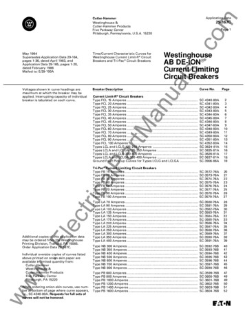
15.1 LIQUID RADIOACTIVE WASTE PROCESSING SYSTEMSLearning Objectives:1. Explain why liquid radioactive waste is separated into reactor-grade andnonreactor-grade wastes.2. List three inputs to the reactor-grade waste subsystem.3. List three categories of nonreactor-grade wastes.4. Briefly explain three liquid radioactive waste processing methods.5. Define the term Adecontamination factor@ (DF).15.1.1 IntroductionThe liquid radioactive waste (LRW) system collects, stores, and processesradioactive or potentially radioactive waste for recycling to the reactor coolantsystem (RCS) or for releasing to the environment. This system (Figure 15.1-1)begins at the interfaces with the reactor coolant pressure boundary, and theinterface valve(s) in lines from other systems, or at those sumps and floor drainsprovided for liquid waste with potential of containing radioactive material. Itterminates at the point of controlled discharge to the environment, at the point ofinterface with the waste solidification system, and at the point of recycle back tostorage for reuse.Provisions are made to sample and analyze these liquids. Based on laboratoryanalysis, these wastes are either recycled for reuse, released under controlledconditions via the service water system, retained for further processing, ortransferred to the solid waste system (Section 15.2) for solidification. The amount ofliquid waste that enters the LRW system is limited so that relatively small quantitiesof generally low level wastes are processed. To limit the input into the LRW system,most of the water discharged from the RCS is processed by the boron recyclesystem (Section 4.1).The liquids that are not processed by the boron recycle system enter the LRWsystem, which is arranged to recycle as much water entering the system aspractical. This is accomplished by segregation of equipment drains and wastestreams to prevent the intermixing of the liquid wastes. The LRW system consistsof two main subsystems which process reactor grade and nonreactor-gradeeffluents. In addition, the system is capable of handling drains which may containreagents or chemicals and has the capability for handling spent demineralizerresins.The LRW system is designed so that at least two valves must be manually openedto permit discharge of liquids to the environment. One of these valves is normallylocked closed. The discharge line also has a control valve that will automatically tripclosed on high effluent activity level.USNRC HRTD15.1-1Rev 1100
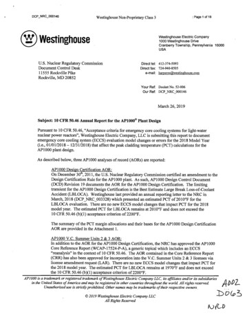
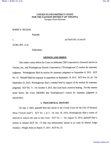
The LRW system is constructed of materials that meet the requirements of thesystem and applicable codes. In addition, all parts or components that may come incontact with borated water are fabricated of or are clad with stainless steel.Equipment and components within the LRW system are located and arranged toreduce radiation exposure to plant personnel during operation and maintenance. Alltanks and process equipment are shielded so that normally occupied areas are inradiation fields of less than 2.5 mrem/hr. Process equipment is located andarranged to provide space for removal and replacement of components and theequipment itself. Process subsystems are arranged to reduce the length of pipingruns. Process equipment, such as filters, ion exchangers and evaporators, areusually located in individual cells. Equipment is designed to facilitate rapiddisconnection for removal, replacement and ease of in-place maintenance. Table15.1-1 lists the liquid waste systems at selected facilities.15.1.2 System Description15.1.2.1 Separation of Reactor-Grade and Nonreactor-Grade LiquidsLiquid radioactive waste is collected in various tanks. The inputs to these tankscome from various drains and are separated and treated as reactor-grade andnonreactor-grade liquids.Reactor-grade liquids are liquids whose tritium concentration is 10% or more ofprimary coolant tritium activity and can be processed for reuse as demineralizedwater or concentrated boric acid solution.Nonreactor-grade liquids are liquids having a tritium concentration of less than 10%of that of the primary coolant and, due to their composition, cannot be processed forreuse.15.1.2.2 Reactor-Grade Water (Recycle)The recycle section is provided to process reactor-grade water which enters theLRW system. Deaerated, tritiated RCS water collected directly in the reactorcoolant drain tank, Figure 15.1-2, may be routed directly to the boron recycle holduptanks for processing in the boron recycle system or routed to the miscellaneouswaste tank. Aerated and tritiated water is collected in the miscellaneous waste tank,Figure 15.1-3.The systems used to process miscellaneous waste include ion exchange,evaporation, or equivalent processes. Evaporation is selected as a primaryprocessing method, as it is very efficient at reducing the amount of contaminatedwater with ionic and particulate contaminates. Various processing methods arediscussed in detail in section 15.1.3 in this chapter. The basic composition of theliquid collected in the miscellaneous waste tank is boric acid and water with someradioactivity. Liquid collected in this tank is evaporated to remove radioisotopes,boron, and air from the water so that it may be reused in the RCS.USNRC HRTD15.1-2Rev 1100
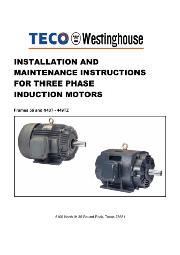
Evaporator bottoms are normally drummed (in the solid radioactive waste system)unless found acceptable for boric acid recycle. The condensate leaving themiscellaneous waste condensate polishing demineralizer enters the monitor tank.When a sufficient quantity of water has collected in the monitor tank, it is sampled todetermine if it is suitable for recycle (to the primary water storage tank for reuse),discharge, or if it must be reprocessed in the LRW system.15.1.2.3 Nonreactor-Grade Water (Waste)This waste category is designed to collect and process nonreactor-grade liquidwastes. These include chemical wastes, detergent wastes, and secondary systemwastes. The inputs to these tanks are gravity drains. Each of these collectionpoints has a pump to recirculate the contents of the collection tank for sampling andfor transferring the liquid for processing. After processing, the liquid is transferred toa monitor tank. The monitor tank has a pump to recirculate the contents of themonitor tank for sampling. Depending on the results of the sample, the monitor tanktransfers the contents for discharge, recycle for reuse, or reprocessing.Chemical WasteInput sources include radiochemistry laboratory drains, chemical cleaning waste,decontamination waste, and other liquid radioactive wastes which contain highconcentrations of chemicals. The chemical waste may be treated separately, asshown in Figure 15.1-4, and transferred to the miscellaneous waste system, ortransferred directly to the solid waste system.Detergent WasteInput sources, Figure 15.1-5, include laundry, personnel decontamination, and otherliquid radioactive wastes containing detergents and soaps. The detergent wastemay be treated separately or processed directly in the solid waste system. Thissystem should be segregated from other waste collection systems to reduceoperational problems with processing equipment.Secondary System WasteInput sources, Figure 15.1-6, include steam generator blowdown, turbine buildingdrains, and ion exchange spent regenerant solutions. The secondary systemwastes may be treated separately, or in the event of primary-to-secondary leakage,the turbine building drains and steam generator blowdown may be treated in themiscellaneous waste system. The ion exchanger spent regenerant solutions maybe treated in the chemical waste system.15.1.3 Processing Methods“Decontamination factor” is a term used to describe the efficiency of a processingmethod removing contaminants from a process stream. The decontamination factor(DF) is the ratio of the initial amount of activity in a stream to the final amount ofactivity in a stream following the treatment by a given process. Therefore, if a givenUSNRC HRTD15.1-3Rev 1100
process has a DF of 2, the final activity level is one half of the original activity.Decontamination factors for liquid waste processing are obtained by the selectionand combination of a number of unit operations. Currently, the principal unitoperations for treating liquid radioactive waste are filtration, ion exchange,evaporation and reverse osmosis.15.1.3.1 FiltrationFiltration is defined as the separation of undissolved particulate, suspended solidsfrom a fluid mixture by passage of most of the fluid through a septum or membranethat retains the solids on or within itself.Cartridge-Type FilterCartridge filters, Figure 15.1-7, are designed with replaceable elements which arediscarded when contaminated. These elements are usually constructed of pressedpaper, matted fibers, or porcelain materials. In general, these types of elements areused in low pressure, low temperature systems.Precoat-Type FilterPrecoat filters, Figure 15.1-8, use elements designed as retainers to prevent aprecoat material from being flushed downstream. The actual filtering of systemcontamination is accomplished by the precoat material. This type of filter is limitedby temperature, flow, and pressure extremes. In addition, the large quantities ofprecoat material which must be disposed of can present significant problems interms of handling and disposal.Filters will remove radioactive particulates but have no effect on ionic removal.Therefore, filters are normally given a decontamination factor of 1.15.1.3.2 Ion ExchangeAn ion exchanger (demineralizer) is a device that uses a polyelectrolyte to exchangemobile ions of equal charge from the surrounding solution. The polyelectrolyte isessentially a plastic bead which has ions weakly attached to it; typically used is HOHtype resin. When a liquid is passed across this bead, it will readily exchange theions on the bead with ions of the same charge in the liquid. There are basically twotypes of resins, cation and anion resins. The cation resin has a positive ionattached in the hydrogen (the H part of HOH resin) form. The anion resin has anegative ion attached in the hydroxide (the OH part of HOH resin) form. Generally,ion exchangers use a combination of these resins and are called mixed-bed ionexchangers or demineralizers.De-ionization with mixed bed ion exchangers is capable of producing water ofexceptional purity. On occasion, the effectiveness of an ion exchanger material maybe impaired due to the accumulation of insoluble materials, such as oil orparticulates, on the surface and the interior of the ion exchanger. It is best to avoidor minimize this fouling by the use of suitable pretreatment filtration.USNRC HRTD15.1-4Rev 1100
The decontamination factor of ion exchangers varies from 1 to 100. This dependsupon the conductivity of the solution, the location of the ion exchanger in theprocess stream, and if the ion exchanger is a single unit or in series with another ionexchanger.15.1.3.3 EvaporationEvaporation is the process by which a solution or slurry is concentrated via boilingthe solvent. This process leaves most of the solids behind, and the condensedsteam is essentially pure water.The basic operation of a waste evaporator is to receive a solution to cause boiling.This boiling causes radioactive gases to leave solution. These gases are collectedand vented to the waste gas system. The steam generated due to boiling iscollected, condensed, and treated as deaerated, essentially pure water, which canbe recycled for reuse. The solution left behind in the evaporator bottoms is calledthe concentrate. The concentrate generally has a high concentration of radioactivematerial, and this solution can be recycled for further processing, or more often, it istransferred to the solid waste system for solidification.Evaporation has a wide application in the nuclear industry for reducing wastevolumes and for reducing the amount of radioactive nuclides in liquid effluents. It isusually used for radioactive wastes that require a high degree of separation and arenot readily treated by low temperature operations such as filtration or ion exchange.In the design of evaporators for concentrating radioactive liquids, vapor separation isthe most important factor, as decontamination of the liquid is the main objective.Volume reduction is a secondary objective, and least important is minimizing theheating costs.Evaporators can separate water from solids very effectively, and a systemdecontamination factor of 104 to 105 is generally expected. However, for presentgeneration waste evaporators to realistically achieve this decontamination factor, theflow rate must be very low, on the order of 15 gpm or less.15.1.3.4 Reverse OsmosisReverse osmosis is a process in which filtering at the molecular level removesdissolved minerals, dissolved organics and biological and colloidal matter fromwater.Osmosis is the natural process whereby pure water flows through a semipermeablemembrane from a dilute solution into a more concentrated solution. This processdilutes the concentrated solution. Reverse osmosis is the process by whichpressure is applied to the concentrated solution thereby forcing pure water to flow inthe reverse direction through the semipermeable membrane.The result of this process is that the concentrated solution becomes moreconcentrated. Reverse osmosis has been found to be very effective in thetreatment of detergent waste. The decontamination factor for the reverse osmosisUSNRC HRTD15.1-5Rev 1100
unit is about 30 for the processing of detergent wastes. The decontamination factorfor all other liquid wastes is 10.15.1.4System Interrelationships15.1.4.1 System Decontamination FactorAs discussed in Sections 15.1.2.1 through 15.1.2.4, various methods are availablefor the processing of LRW. Usually the processing system employs several of thesein series. To determine the decontamination factor for a given process stream, theproduct of all the methods used in that stream is calculated.As an example, a hypothetical system consists of an inlet filter, an evaporator, anion exchanger, and an outlet filter. The decontamination factor for each of thesemethods would be: inlet filter - 1, evaporator - 104, ion exchanger - 10, and outletfilter - 1.To determine the system DF, the product of the component DFs is calculated:System DF 1 x 104 x 10 x 1 105Therefore, the DF for this hypothetical process stream is 100,000.15.1.5 SummaryThe liquid radioactive waste system is designed to collect, store, process anddispose of radioactive or potentially radioactive liquids. The liquids are collected bygravity drains and segregated into various tanks as reactor-grade and nonreactorgrade liquids. This segregation is necessary because the different grades of liquidsmust be processed by different methods.There are different methods of processing these collected liquids. The processingmethods include filtration, ion exchange, evaporation, and reverse osmosis.Normally, one or more of these processing units will be utilized in the processstream.After processing, the liquid is transferred to monitor tanks. The liquid is sampled,and depending upon the results of the sample, is recycled for reuse, reprocessed, orreleased to the environment.With today’s emphasis on limiting discharges from the LRW system to theenvironment, the LRW system is designed to recycle as much liquid as possible, tolimit the amount of radioactivity released to the environment, and to limit the dosesreceived by plant personnel. Therefore, great emphasis is placed on maximizing thedecontamination factors for the process stream and volume reduction. Liquid thatcannot be recycled (due to high activity, chemical composition, etc.) is transferred tothe solid waste system for processing. After solidification, this waste is placed instorage on site, or transported to a permanent burial facility.USNRC HRTD15.1-6Rev 1100
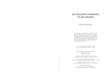
Table 15.1-1Liquid Waste Systems and CapacitiesPlant NameChemicalDrainLaundry & ReactorHot Shower Cont. DrainSpent ResinStorageWaste Holdup WasteMonitorR.E. Ginna3752 @ 6003502-?21,000KewauneeTo H/U Tank 2 @ 7003501-?24,490Point Beach 1 600*& 22 @ 7003501-?21,000*Prairie Island 1 600*&22 @ 7003501-?24,490*Beaver Valley1&22 @ 1,300* 3501,400*2 @ 5,000J. M. Farley 1 600&210,000*3502 @ 2,600*1000Sharon Harris?2@25,000*3502-?25,000North Anna?1,1002 @ 5,000H. B. Robinson 6002 @ 60056530024,000San Onofre?7841-?3 @ 52,0002 @ 3,740V. C. Summer 60010,0003502,60010,0002 @ 5,000Surry 1 & 2?2,019*2 @ 2,390*2 @ 3,000Turkey Point?3 @ 6003502 @ 10,000*2 @ 5,000Byron 1 & 0*3505,000*?Calloway60010,000350?10,0002 @ 5,000Catawba600*10,0003502 @ 5,0002 @ 5,000CommanchePeak600*10,000*3504,100*10,000*2 @ 5,000*D. C. Cook600*2 @ 600*350300*2 @ 25,000*Diablo Canyon 1,0002 @ 1,0004002 @ 15,0002 @ 15,000McGuire 1 & 2 600*10,000*3502 @ 5,0005,000*USNRC HRTD?37515.1-72@10,0002 @ 5,0002 @ 6,080Rev 1100
Table 15.1-1 (cont’d)Liquid Waste Systems and CapacitiesPlant NameChemicalDrainLaundry & ReactorHot Shower Cont. DrainSpent ResinStorageMillstone 3To Hi LvlWasteTo Lo LvlWaste3503,200Salem6002 @ 600*565300Seabrook 1 &2Waste Holdup WasteMonitor2 @ 21,000*2 @ 25,000350Sequoyah 1 600*&22 @ 600*2 @ 25,000*2 @ 25,000*3502,600*3472,60024,700*10,000*Trojan6,5002 @ 15,322Vogtle600*10,000*3502,60010,0002 @ 5,000Wolf Creek60010,0003502,60010,0002 @ 5,000Zion 1 & 212,5002 @ 1,5003505,0002 @ 30,0006,000* common to both unitsUSNRC HRTD15.1-8Rev 1100
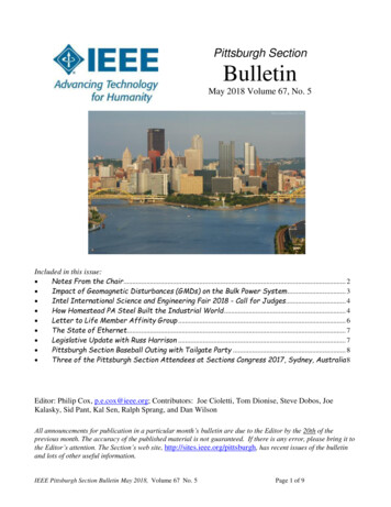
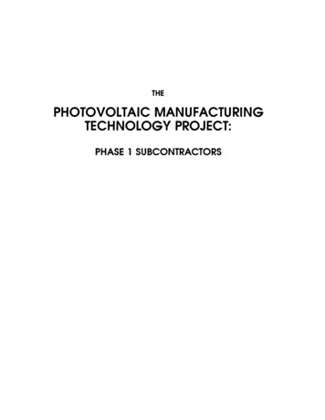
Table 15.1-2Liquid Waste Evaporators and Miscellaneous TanksPlant NameWasteWasteWaste Evaporator MiscellaneousEvaporatorEvaporatorCondensate Tank TankCapacity (gpm) ConcentrateTankR.E. GinnaKewaunee2 @ 6002-?CommentsUltra-filtrationas a prefilterfor evaporator2 @ 1,000Sump Tank 600Point Beach 1 1 - ?& 21,000*Sump Tank 600*Prairie Island1&22 @ 1,000*Sump Tank 600* SGBDAeratedDemins notfor WasteHandling2-5Beaver Valley 61&21,350*2 @ 3,000*Decon Drain1,400*J. M. Farley 1 15&2?5,000Floor Drain10,000Sharon Harris Fluid Bed Dryer 5,000North Anna6 ClarifierH. B.RobinsonSan Onofre9252 @ 1,500Lo Level Waste2 @ 11,2502 @ 1,000WasteCondensate3 @ 11,250ion exh / gasstripperV. C. SummerDecon Drain2,6005,000Surry 1 & 2not usedTurkey Point2 - 15Byron 1 & 23 - 30USNRC HRTDFloor Drains4 @ 25,0005,000Floor Drain10,000Lo Level Waste2 @ 2,8756,400*2,000*15.1-934 - 35 ftWasteProcessingDemins35 - 10 ftWasteProcessingDeminsAux Bldg FloorDrain 2 @ 8,000Rev 1100
Table 15.1-2 (cont’d)Liquid Waste Evaporators and Miscellaneous TanksPlant NameWasteWasteEvaporatorEvaporatorCapacity (gpm) ConcentrateTankWaste Evaporator MiscellaneousCondensate Tank TankBraidwood3 - 302,000*Aux Bldg FloorDrain 2 @ 8,0005,000Floor Drain2 @ 10,0002 @ 5,0003,0005,000Floor Drain10,000Cont. Vent UnitDrain 5,000Commanche 1-15Peak5,000*5,000*Floor Drain2 @ 10,000WasteDvaportor FloorDrainRev. Osmosis LaundryD.C. Cook2 - 15 and1-24,000*2 @ 1,500*DiabloCanyonMobile RadWaste2,000Floor Drain2 @ 10,0001 @ 30,000MobileRadwastePurification(ChemNuclear)Floor Drain2 @ 10,000Cont. VentCond. Drain4,0006,400*CallowayCatawba1 - 15McGuire 1 & 1-152Millstone 33,0005,000*1-35CommentsLo Level WasteDrain 2 @ 4,000SalemConcentratesHolding Tank 500Seabrook 1&2Floor Drain2 @ 10,000Sequoyah 1 1 - 30&23 @ 2,000*Aux Bldg Sump600*PortableFiltrationSystem(60gpm)2 @ 15,322Trojan1 - 152 @ 15,3221,300Dirty Waste Drain5,900Vogtle 1 & 21 - 152,000*5,000Floor Drain 10,000 2 @ 5,000USNRC HRTD15.1-10Rev 1100
Table 15.1-2 (cont’d)Liquid Waste Evaporators and Miscellaneous TanksPlant NameWasteEvaporatorCapacity(gpm)Wolf CreekZion 1 & 21 - densateTankMiscellaneousTank1,0005,000Floor Drain10,0002 @ 8,000Aux Bldg Sump250CommentsSpray FilmTypeEvaporator* common to both unitsUSNRC HRTD15.1-11Rev 1100
15.1.3 Processing Methods "Decontamination factor" is a term used to describe the efficiency of a processing method removing contaminants from a process stream. The decontamination factor (DF) is the ratio of the initial amount of activity in a stream to the final amount of activity in a stream following the treatment by a given process.