Transcription
Fast EMC Diagnostics of Complex On-BoardRadio Systems with Use of Experimentally RefinedWorst-Case and Conditionally Worst-Case Modelsof "Transmitter-to-Receiver" InteractionsEugene SinkevichEMC R&D LaboratoryBelarusian State University ofInformatics and RadioelectronicsMinsk, Belarusesinkevich@bsuir.byVladimir MordachevEMC R&D LaboratoryBelarusian State University ofInformatics and RadioelectronicsMinsk, Belarusmordachev@bsuir.byAlexey GalenkoEMC R&D LaboratoryBelarusian State University ofInformatics and RadioelectronicsMinsk, Belarusemc@bsuir.byYauhen KharasheuskiResearch Instituteof Automation FacilitiesMinsk, Belaruskharasheuski-riaf@tut.byMikalai PanchankaResearch Instituteof Automation FacilitiesMinsk, Belaruspanchanka-riaf@tut.byViktar BobraResearch Instituteof Automation FacilitiesMinsk, Belarusbobra-riaf@tut.byAbstract—An improved computationally efficient techniquefor EMC diagnostics of radio equipment of complex on-boardradio-electronic systems is presented. The first improvement isbased on the use of worst-case and conditionally worst-casemathematical models to describe unwanted electromagnetic(EM) interactions between transmitters and receivers of thesystem, which allows to detect all potentially dangerousinteractions rapidly and avoid second-type errors whenassessing the danger of these interactions. The secondimprovement concerns the iterative refinement of worst-caseand conditionally worst-case models of potentially dangerousinteractions (including models of transmitter radiation spectra,receivers susceptibility characteristics, amplitude-frequencycharacteristics of decoupling antenna filters and EM spuriouscouplings between antennas of on-board system) by the use ofboth numerical simulation methods and measurements toimprove the accuracy of EMC diagnostics. The thirdimprovement is associated with the use of an extremelyeffective technique of discrete nonlinear behavior simulation ofradio receivers’ operation in a severe EM environment formedby a set of powerful EM radiations from radio transmitters ofthe analyzed on-board system and a variety of external EMfields generated by various radio systems of different services.Keywords—EMC diagnostics, on-board system, receiver,transmitter, antenna, worst-case model, electromagneticcoupling, intermodulationI. RI– amplitude-frequency characteristic– antenna pattern– complex on-board local radio system– double frequency characteristic– double frequency diagram– discrete linear analysis– discrete nonlinear analysis– electromagnetic– electromagnetic compatibility– electromagnetic environment– radio receiver– radio transmitter– spurious coupling– spurious "transmitter-to-receiver" interactionII.INTRODUCTIONIntrasystem and intersystem EMC diagnostics are animportant parts of the design and ensuring normal operationof complex local on-board radio systems (CLRS), as thesediagnostics can detect, identify and take actions to eliminatepotentially hazardous spurious "transmitter-to-receiver" EMinteractions (STRI) between CLRS radio transmitters andreceivers, as well as promptly detect, identify and prevent theinfluence of undesirable effects of external sources of EMfields on the operational efficiency of these systems.Typically, performing of such CLRS EMC diagnosticrequires a multivariate STRI hazard analysis (taking intoaccount useful and unwanted components of the transmitterspectra and receiver susceptibility characteristics in a widefrequency band, spurious EM couplings between antennas,characteristics of cables, frequency filtering systems andactive components, for example, antenna amplifiers) forvarious options for the on-board location of antennas andmodes of operation of CLRS radio equipment, and also forvarious protective technical and organizational solutions. Inaddition, intersystem EMC analysis is often required for avariety of application scenarios for the on-board systemunder consideration that differ in external electromagneticenvironment (EME).In practice, there are many choices (for how CLRS areimplemented, configured, and operated) to be analyzed, soreducing the EMC analysis time for each case is especiallyimportant. With a large number of potentially dangerousSTRIs and existing limitations on computing power, such ananalysis is possible only using the IEMCAP technology [1],which assumes the use of simplified pessimistic models ofamplitude-frequency characteristics (AFC) of potentiallydangerous STRIs. In particular, this technique isimplemented in [2, 3], its practical efficiency is confirmed bythe results [4-7].The most challenging problems of EMC computerdiagnostics of CLRS are following: 2021 IEEE. Personal use of this material is permitted. Permission from IEEE must be obtained for all other uses, in any current or futuremedia, including reprinting/republishing this material for advertising or promotional purposes, creating new collective works, for resale orredistribution to servers or lists, or reuse of any copyrighted component of this work in other works.DOI: 10.1109/EMC/SI/PI/EMCEurope52599.2021.9559378
1) The lack of complete and reliable information aboutcharacteristics of CLRS equipment, for example, aboutcharacteristics of radiation spectra of radio transmitters(RT), susceptibility of radio receivers (RR), and AFC ofantennas in a wide frequency range (up to 3 decades). Anillustration of this circumstance, in particular, can be thedata [8] and the results of measurements of the spectra ofinterference emitters [9], showing that the pessimism ofmodels [1] of the RTs output spectra and RRs characteristicsof susceptibility can reach 20-30 dB at all frequencies,except for frequencies of narrowband sputious componentsof RTs output spectrum and RRs spurious responses;2) A sufficiently large number of STRI and externalmodulated EM fields (up to 103 . 105) to be analyzed, and alarge number of CLRS implementation options andoperation scenarios for which EMC analysis is required,with significant resource constraints (computational, time,etc.).Frequency domain EMC Discrete Linear Analysis (EMCDLA) technology developed by the IEMCAP [1] and basedon the worst-case analytical models of spurious couplings(SC) in CLRS between RTs and RRs antennas and on theintegrated interference margin (IIM) as the EMC systemcriterion, appears to be quite effective in solving EMC CLRSproblems under the following conditions:a) If it is implemented at the modern level [2, 3] usingmuch more detailed frequency sampling of spectra andcharacteristics of susceptibility (105-106 samples and more),in comparison with [1];b) If it is supplemented with the time domain EMCdiscrete nonlinear analysis technology (EMC DNA) [1012], which provides high computational efficiency in theanalysis of nonlinear effects (intermodulation, blocking,cross modulation, conversion of local oscillator noise, etc.)during radio reception in complex EME, including the useof specialized techniques [13, 14] for measuring parametersof the input nonlinearity of CLRS RRs.An important way to improve the objectivity andaccuracy of EMC DLA & DNA of CLRS is a sequentialiterative refinement of worst-case models of potentiallyhazardous STRIs between CLRS equipment. In early stagesof CLRS life cycle, this refinement is usually achievableonly by detailed circuit-level mathematical modeling of RTsspectra and RRs susceptibility characteristics, as well aselectrodynamic modeling of each of the options for therelative spatial arrangement of CLRS antennas [4-7]. At laterstages, a more significant refinement of these models ispossible based on the results of measurements ofcharacteristics of CLTS equipment and SC.The goal of this work is to improve the method of fastcomputer diagnostics of EMC of CLRS radio equipment(developed in [3-7] and based on the use of EMC DLA &DNA technologies) by using both pessimistic andconditionally pessimistic models of CLRS STRI, and also byrefining these models using the measurement results.III. STAGES OF FAST EMC DIAGNOSTICS OF CLRSThe improved technique for the fast EMC diagnostics ofCLRS is based on multi-variant EMC DLA & DNA ofCLRS equipment operation in severe EME with the use ofworst-case and conditionally worst-case models of STRIs.The technique includes the following main stages.A. At CLRS designing1) Develop a 3D geometric model of CLRS with help ofCAD system. This model helps to consider different variantsof allocation of RT and RR antennas and define allcharacteristics that affect EM SCs between the antennas(geometry and material of hull, characteristics of antennaplacement, etc.).2) Develop worst-case models of STRIs for differentvariants of CLRS implementation. This includes models ofEM SCs between antennas, models of antenna patterns (AP)to analyze impact of external EME, models of main andspurious emission spectra for each RT in a wide frequencyrange (up to ten times exceeding the maximum workingfrequency), models of susceptibility characteristics of eachRR via the main, adjacent, and spurious reception channelsin a wide frequency range (up to ten times exceeding themaximum tuning frequency of RR), and models offrequency selectivity of feeder components (filters,preselectors, combiners, etc.).3) Develop a model of external EME. The model has aform of an ensemble of external EMFs with predefinedpower characteristics, frequency spectra, direction of arrivaland polarization. The model is developed based on data onallocation and operation of external RTs (ground-based, RTsof other CLRSs, of aircrafts, etc.); the radiomonitoring datacould also be involved.4) Perform the EMC DLA with the use of basic worstcase models [1] of STRIs and taking into account externalEME for each variant of placement and elevation of CLRSantennas. The Integrated Interference Margin (IIM) is usedas a criterion of EMC [1]; it is calculated for each receptor(i.e., RR) as follows: n PIIM 10 lg IM f A i [dB], IM I ,S i 1 (1)where PI [W] is the level of unwanted signal at the receptor,S [W] is the receptor susceptibility to interference, fA [Hz] isthe analyzed frequency, n is the number of analyzedfrequencies (called frequency samples in [1,10,11]), IM isthe point Interference Margin at a fixed frequency.As a result of this stage, the set of potentially dangerousSTRIs that can cause radio interference in RRs of CLRS isdetected.5) Refine the models of potentially dangerous STRIs.Each potentially dangerous EM SC "Antenna-to-antenna" isanalyzed by the use of numerical methods (FDTD, MoM,etc.). Such analysis is performed in the following order:models of AFCs of S-matrix elements which characterizethe SC in predefined frequency ranges are developed andrefined by small variations in values of antenna parametersand coordinates; the worst-case envelope of the AFC of"antenna-to-antenna" SC is constructed; AP models takinginto account antennas’ design features and orientation wrtthe elements of CLRS hull structure and underlying surfaceare refined (for more accurate analysis of impact of externalEME).The worst-case envelope of the AFC is calculated foreach "antenna-to-antenna" SC as follows:
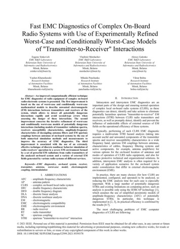
H ik ( f ) E nv H 1ik ( f ), H 2ik ( f ),., H Nik ( f ) ,(2)where f is the frequency, H1ik( f ) is the AFC of S-parameterSik obtained for the SC between antennas with the numbers iand k for the first fixed set of antenna parameters andcoordinates, H2ik( f ) is AFC of Sik obtained for the second setof antenna parameters and coordinates, etc.; Env{.} denotesthe worst-case envelope construction procedure described in[4-7]. Note that it is necessary to define the initial (reference)values of antenna parameters, based on information takenfrom technical specifications.Then the discrete models of RT radiation spectra and ofRR susceptibility characteristics are refined, e.g., by the useof numerical circuit-level simulation.A useful technique is to use conditionally pessimisticmodels. By them we mean such models, the pessimisticnature of which is ensured when certain conditions are met.As an example, we consider the VHF RR susceptibilitycharacteristic's models synthesized based on data from theRR technical specification and shown in Fig. 1. Outside themain reception channel, the pessimistic model is the lowerenvelope of the susceptibility levels of the spurious receptionchannels, and the conditionally pessimistic model describesthe susceptibility outside the spurious reception channels.Because the conditionally pessimistic model does notdescribe the spurious reception channels (image channel,spurious combination channels, etc.), then such a model ispessimistic, provided that, as a result of the selection of theoperating frequencies of on-board RTs and the analyzed RR,the impact of RTs main and spurious oscillations on the RRspurious channels is excluded.and RRs spurious channels, by frequency planning. Theadequacy of this approach is determined by the fact that theprobability of successful elimination of the indicatedinterference (as well as nonlinear interference) by frequencyplanning is rather high, since for each of the analyzed RTand RR several thousand frequency channels are available.6) Repeat the EMC DLA (ref. stage 4) with the use ofrefined models of potentially dangerous EM SCs, RTradiation spectra, and RR susceptibility characteristics. Thisanalysis refines the estimation of danger of STRIs detectedearlier at stage 4.7) Select the most promising variants of CLRSrealization for further detailed analysis. This variants shouldbe charectrized by the absence of interference via the mainreception channels and the least possible levels of out-ofband input disturbances. If necessary, a set of measures toeliminate linear interferences between the RTs and RRs isdeveloped for each selected variant of location of CLRSantennas (and then stage 4 is repeated taking into accountthe implementation of these measures).8) Perform the EMC DNA of CLRS for the situationsremaining potentially dangerous in terms of nonlinearinterference [10-12]. In order to perform the EMC DNA, thenonlinearity and selectivity characteristics of RR throughthe antenna input must be determined taking into accountpeculiarities of structure, components, and frequencyconversions in RR. The best result of the determination canbe achieved by involving the DFT technique [13,14] thatmakes it possible to detect, identify, and measure parametersof all existing linear and nonlinear paths of probable RRdamage by disturbances through the antenna input, as wellas to measure the RR input nonlinearity rather accurately.9) Develop measures to eliminate nonlinear radiointerferences. Technical (filtering, shadowing, cancellation,etc.) and organizational (time division, frequency planning,etc.) measures not related to change in location of antennasare considered.Fig. 1. Models of susceptibility characteristic RR of VHF transceivertuned at 80.2 MHz: worst-case model (blue line) and conditionally worstcase model (red line).Similarly, the model, which is the upper envelope of thespectrum of main, out-of-band and noise RT oscillations, butdoes not describe its narrow-band spurious oscillations, isconditionally pessimistic (i.e., pessimistic, provided that theinterferences which are caused by impact of TR spuriousoscillations through the main and spurious channels of onboard CLRS RRs are eliminated by selecting the operatingfrequencies of this TR and on-board RRs).The use of conditionally pessimistic models of RTsspectra and RRs susceptibility characteristics, from whichinformation about RTs narrow-band spurious oscillations andRRs spurious channels is purposefully removed, makes itpossible to estimate the levels of unwanted effects fromCLRS RTs at the inputs of CLRS RRs, subject to successfulremoval of interference caused by spurious RTs oscillationsNote: In the course of EMC diagnostics of on-boardCLRS, it is often essential to take into account not onlyantenna-to-antenna SCs but also other kinds of EM SCs(antenna-to-cable, cable-to-cable, antenna-to-equipmentcase, external EM field-to-cable, etc.). For this purpose,procedures 1 7 are carried out as a part of the EMCanalysis based on simulation of these SCs.B. At CLRS physical implementationAfter performing the above EMC diagnostics at theCLRS design stage, its results were refined during theCLRS physical implementation (CLRS prototypedevelopment). At this stage, the following was performed.1) Measurements of output spectra of all RTs of CLRSare performed (similar to how it was done in [9]); atdifferent RT tuning frequencies, the levels of out-of-bandand spurious oscillations, as well as their frequency bands,are determined.2) Measurements of susceptibility characteristics of allRRs of CLRS are performed (for example, using technique[13, 14]) at different RRs tuning frequencies; frequenciesand susceptibility levels of all spurious channels detected inthe RRs are determined, as well as all types and orders ofintermodulation channels of RRs nonlinear interference.
3) Measurements of AFC of SCs "Antenna-antenna" areperformed.4) AFCs of all elements of feeders (antenna filters,decoupling unit and other elements used to suppressinterference) are measured.5) AFCs worst-case mathematical models for antennafilters, decoupling units and SC "Antenna-antenna" arespecified based on the measurement results.6) EMC DLA & DNA procedures are repeated in orderto eliminate those STRIs, the danger of which turned out tobe overstated due to the pessimistic nature of theirtheoretical mathematical models.7) Undesirable combinations of RTs and RRs tuningfrequencies are determined, at which interference throughthe main and spurious RRs channels from narrowbandspurious RT oscillations and intermodulation interferencegenerated by RTs signals and strong signals of externalEME is possible (on this stage only those STRIs areconsidered, the danger of which is confirmed by theprevious stage).8) The set of conditionally worst-case models of RTsoutput spectra and the RRs susceptibility characteristics arerefined, from which the RTs narrowband spuriousoscillations and the RRs spurious channels are deliberatelyremoved (since the interference caused by these oscillationsand channels is eliminated by frequency planning byeliminating the unwanted combinations of RTs and RRsworking frequencies).9) EMC DLA & DNA procedures using refinedconditionally worst-case models of RTs output spectra andRRs susceptibility characteristics at different tuningfrequencies are performed (in order to confirm that themeasures taken will eliminate interference to CLRS RRsfrom CLRS RTs at CLRS operation in given external EME).IV.Fig. 3. CLRS primary block diagram.After completing procedures 1-8 in Section B above, arefined EMC analysis of the CLRS equipment using themeasurements was performed in the following sequence:1) EMC DLA using models refined based on the resultsof measuring the output spectra of all RTs, the susceptibilitycharacteristics of all RRs and AFCs of all potentiallydangerous SC. Refined models of phenomena that aresubject to strong variability during the CLRS operation, it isadvisable to make pessimistic, i.e. to find the envelopes ofthe measurement results (an example of such a model isshown in Fig. 4). As other models, it is possible to use themeasurement results directly (an example of such a model isshown in Fig. 5).PRACTICAL IMPLEMENTATIONThe technique of fast EMC diagnostics of complex onboard radio systems with the use of experimentally refinedworst-case and conditionally worst-case models of"transmitter-to-receiver" interactions was tested at thedevelopment of a specialized communication and controlvehicle, the 3D geometric model of which (with antenna'slayout adopted after the STRI and EMC DLA simulations atthe CLRS design stage) is shown on Figure 2. Figure 3shows the structure of its airborne CLRS.Fig. 2. 3D CAD model of location of CLRS antennas on vehicle body.Fig. 4. AFC of the SC between VHF antennas of CLRS: red line measurement result, blue line - refined pessimistic (worst-case) modelFig. 5. AFC of the SC through an antenna filter unit (AFU): blue line pessimistic model based on data from technical specification; the red line isthe refined model obtained from the measurement results.
In fig. 6 the image of the double frequency characteristic(DFC) [13,14] of RR of the first VHF transceiver is given;fig. 7 shows the image of its double-frequency diagram(DFD) - a map of DFC levels (levels below the standardresponse corresponding to the real RR sensitivity are notdisplayed on the DFD). In fig. 6 and 7, the RR spuriouschannels, as well as intermodulation channels up to the 7thorder inclusive, are detected. In fig. 8, the measured RRsusceptibility characteristic of the first VHF transceiver isshown as an example, on which the corresponding RRspurious channels are also observed.of RT and RR tuning frequencies, at which interference forRRs from narrow-band spurious RTs oscillations is possible.Fig. 8. Measured RR susceptibility characteristic of the first VHFtransceiver.Fig. 6. DFC of RR of VHF transceiver.2) EMC DLA using conditionally pessimistic models ofRTs output spectra and RRs susceptibility characteristics inorder to performing of intrasystem EMC diagnostics ofCLRS after the introduction of restrictions on the RTs andRRs operating frequencies (accepted at the previous stage ofthe analysis). At this stage, an additional unacceptablecombinations of frequency channels of RTs and RRsoperation may be revealed, due to the effect of wideband(out-of-band and noise) components of the RTs spectra onthe main and spurious channels of RRs reception. Based onthe results of this stage of the analysis, a decision is made onthe effectiveness of the measures taken to ensure EMC andon the need for additional measures to protect RR fromintrasystem interference. Fig. 9 shows an example of theresults of DLA of EMC of transceivers, located on vehiclebody, using conditionally-pessimistic models of RTs outputspectra and RRs susceptibility characteristics.Fig. 9. Results of the EMC DLA of CLRS using conditionally pessimisticmodels: red line - characteristic of receptor susceptibility (RR of VHFtransceiver), lines of other colors - spectra of signals of RTs of HF andVHF transceivers at the antenna input of the receptor (An example).Fig. 7. DFD of RR of VHF transceiver.The results of this stage made it possible to establish theabsence of interference for the operation of UHF & SHFtransceivers, as well as to determine all channels of on-boardRRs affected by the narrowband spectra components of onboard RTs, and to clarify the set of unwanted combinations3) EMC DNA using technology [10-11] and nonlinear RRmodels obtained using the results of measurements of theparameters of front-end nonlinearity of RRs using ADFTtechnology [13,14]. As an example, Fig. 10 shows the totalspectrum of unwanted signals observed at the output of theRR nonlinear model of VHF transceiver. This spectrumcontains both signals of RTs of HF and VHF transceivers,and intermodulation components of 3 . 7 orders.Based on the results of the last stages of the CLRSintrasystem EMC diagnostics, a decision is made on the
sufficiency or insufficiency of organizational measures(automatic control of the simultaneous operation of CLRSradio equipment and the exclusion of the use of dangerouscombinations of operating frequencies using the createdcorresponding database) and technical (frequency and spatialfiltering, blanking, etc.) to ensure EMC.oscillation spectra, RRs characteristics and frequencyresponses of the decoupling filters provides improvedaccuracy of the EMC DLA & DNA results, allowing topredict the CLRS performance characteristics, confirmed bytesting its prototypes.4) In case of insufficient repeatability of thecharacteristics of some samples of CLRS on-boardequipment (transceivers, antennas, filters), its replacementrequires repeating the last stages of EMC diagnostics withthe correction of the list of prohibited combinations ofoperating frequencies of on-board RTs and RRs.REFERENCES[1][2]Fig. 10. Results of EMC DNA for RR of VHF transceiver tuned to 81MHz: spectrum of unwanted signals at the output of the RR nonlinearmodel (green line) and the susceptibility characteristic of the receptorconnected to the output of the nonlinear model (red line). TheHammerstein-Wiener model with 15th order polynomial model of RRfront-end inertialess nonlinearity is used.In particular, after analyzing the results of this stage ofcomputer diagnostics of intrasystem EMC of the consideredCLRS, the LPF and HPF (see Fig. 3) were replaced withappropriate bandpass filters, which made it possible toexclude intermodulation interference created by outputsignals of on-board RTs, and also essentially decrease levelsof interference specified by broadband components of theRTs output spectra in the main and spurious RR frequencychannels, as well as somewhat reduce the number ofprohibited combinations of RTs and RRs tuning frequenciesof on-board VHF transceivers.V.CONCLUSIONThe presented testing results (see section IV) allowed usto come to the following conclusions about the effectivenessof the fast EMC diagnostics technology of complex on-boardradio systems with the use of experimentally refined worstcase and conditionally worst-case models of "transmitter-toreceiver" interactions:1) Execution of EMC DLA & DNA using "worst-case"models [1], obtained on the basis of technical specificationsof CLRS equipment, when developing and providing EMCof vehicle CLRS, gives too pessimistic results of diagnosticsof intrasystem EMC, far from reality, despite the use ofmuch more detailed frequency sampling of spectra andcharacteristics of susceptibility compared to [1].2) Execution of EMC DLA & DNA using "worst-case"models, refined by detailed electrodynamic modeling of SCwith variations in technical parameters, characteristics ofplacement and matching of on-board antennas [4-7],provides clarification of characteristics of SC betweenantennas, which is necessary for the adoption of designsolutions. However, the accuracy of such EMC diagnostics issignificantly limited due to the lack of complete and reliableinformation on the RTs oscillation spectra, RRssusceptibility characteristics and AFCs of the decouplingfilters.3) Refinement of the models of "Transmitter-toReceiver" interactions based on measurements of win, G.Capraro, "Intrasystem Electromagnetic CompatibilityAnalysis Program (IEMCAP)", IEEE Trans. on EMC, 22, Nov. 1980,pp. 224–228.A.Drozd, T.Blocher, A.Pesta, D.Weiner, P.Varshney, I.Demirkiran,"Predicting EMI Rejection requirements using expert system basedmodeling & simulating techniques", Proc. of the XV-th Int. WroclawSymp. on EMC, Poland, Wroclaw, 2000, Part 1, pp.313-318V.Mordachev, P.Litvinko, "Expert System for EMC Analysis TakingInto Account Nonlinear Interference", Proc. of the XVI-th Int.Wroclaw Symp. on EMC, Poland, Wroclaw, June 25-28, 2002,pp.265-270.V.Mordachev, E.Sinkevich, D.Tsyanenka, A.Krachko, G.Slepyan,I.Bezruchonok and A.Karaim, "EMC Diagnostics of Complex RadioSystems by the Use of Analytical and Numerical Worst-Case Modelsfor Spurious Couplings Between Antennas", Proc. of the Int. Symp.“EMC Europe 2016”, Wroclaw, Poland, 2016, pp. 608–613.V.Mordachev, E.Sinkevich, Y.Yatskevich, A.Krachko, P.Zaharov andXie Ma, "Simulation of Nonlinear Interference in Aircraft SystemsOperating in Complex Electromagnetic Environment Created byLand-Based and Air-Based Wireless Systems", Proc. of the Int.Symp. "EMC Europe 2017", Angers, France, 2017, 6p.V.Mordachev, E.Sinkevich, D.Tsyanenka, A.Krachko, Y.Yatskevich,A.Shuldov, A.Vodchits, Yingsong Li, Tao Jiang and Wei Xue,"Multi-Variant Discrete Analysis of EMC of On-Board RadioEquipment with Use of Worst-Case Models", Proc. of the Int. Symp."EMC Europe 2018", Amsterdam, Netherlands, 2018, pp. 190–195.V.Mordachev, E.Sinkevich, D.Tsyanenka, Y.Arlou, A.Svistunou,A.Galenko, A.Polkanov, A.Krachko, Yingsong Li, Tao Jiang and WeiXue, "EMC Diagnostics of Complex Ship Radioelectronic Systemsby the Use of Analytical and Numerical Worst-Case Models forSpurious EM Couplings", Proc. of the Int. Symp. "EMC Europe2019", Barcelona, Spain, Sept. 2– 6, 2019, p.214-219.A Handbook Series on Electromagnetic Interference andCompatibility. By Donald R.J.White. Published by: Don WhiteConsultants, Inc. Germantown, Maryland, 1971-1981.M.Miller, C.Behnke, G.Guida, "ARMS, an Automated MeasurementSystem for Broadband Modeling of Tx/Rx Devices for High-FidelityRF Interference Analysis", Proc. of the Int. Virtual Conf. “EMCEurope 2020”, Rome, Italy, Sept. 23-25, 2020, 5 p.V.I.Mordachev, E.V.Sinkevich " “EMC-Analyzer” expert system:improvement of IEMCAP models" // XIX Int. Wroclaw Symp. onEMC. 2008, pp. 423–428.S.L.Loyka, J.R.Mosig, "New Behavioral-Level Simulation Techniquefor RF/Microwave Applications. Part I: Basic Concepts", Int. Journalof RF and Microwave Computer-Aided Engineering, vol. 10, No.4,July 2000, pp. 221-237.E.Sinkevich, V.Mordachev, "Characterization of Radio Receiver’sFront-End Nonlinearity by Measurement of Spurious-Free DynamicRanges", Proc. of the Int. Symp. on EMC “EMC Europe 2012”,Rome, Italy, Sept. 17-21, 2012, 6 p.V.Mordachev, "Automated Double-Frequency Testing Technique forMapping Receiver Interference Responses", IEEE Trans. on EMC,42, 2, May 2000, pp. 213–225.V.Mordachev, E.Sinkevich, D.Petrachkov. Representation andAnalysis of Radio Receivers’ Susceptibility and Nonlinearity by theUse of 3D Double-Frequency Characteristics, Proc. of thje Int. Symp.“EMC’14/Tokyo”, Tokyo, Japan, May 12-16, 2014, pp. 689-692.
Frequency domain EMC Discrete Linear Analysis (EMC DLA) technology developed by the IEMCAP [1] and based on the worst-case analytical models of spurious couplings (SC) in CLRS between RTs and RRs antennas and on the integrated interference margin (IIM) as the EMC system criterion, appears to be quite effective in solving EMC CLRS