Transcription
ASTC Strawman BPR Proposal Ver. 2011Ͳ4Ͳ5.2 Manfred E. Schabes1), Thomas Albrecht1), Rene van de Veerdonk2), David Kuo2)1)Hitachi GST, San Jose Research Center2)Seagate Technology, Recording Media TechnologyThis report summarizes efforts of the ASTC BPR Systems Workgroup to develop BPR strawmanproposals for densities up to 4 Tb/in2. We seek to build a common denominator forunderstanding key geometric and magnetic performance parameters of BPR, and to provide afoundation for a BPR roadmap that is distinguished by a broad consensus across the ASTCmember companies.Clearly, some of the estimates are soft ("strawman proposal") and are expected to be refined byfuture research of the ASTC workgroups. Indeed, one of the main goals here is to make visibleto the functional ASTC Work Groups advantages and disadvantages of various approaches andthereby motivate a focused effort for finding optimum solutions at the component and systemslevel. These efforts will be crucial for commercial deployment of BPR in the future.The report is organized into the following main sections.1.2.3.4. BP media architecturesWrite architectureKey parameters of the BPR strawman proposals for 2 Tb/in2 and 4 Tb/in2Technology gaps 1
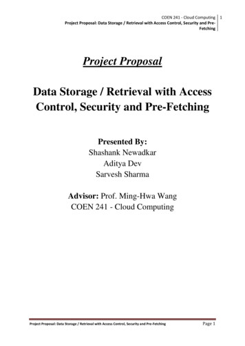
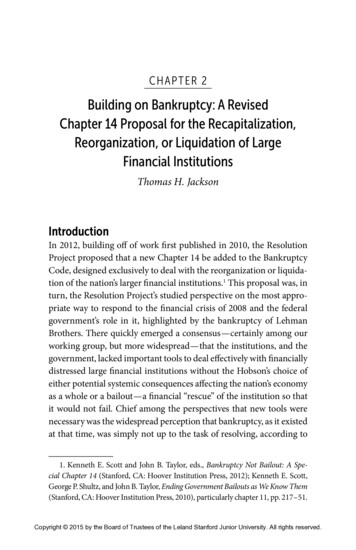
1. BP media architectures Three design strategies are considered for the BP media.1. high-BAR BPM,2. low-BAR BPM,3. hyper-track BPM.The islands may be arranged on square lattices, staggered lattices, or hexagonal lattices (asshown below) with obvious generalization to rectangular type lattices for higher BAR. FIG. 1. Island lattices 2. Write architecture For the write architecture, three approaches are considered as well (see fig. 2).1. centered writing,2. shingled writing,3. hyper-track writing. 2
FIG. 2. Write architectures. The blue boxes represent a (simplified) projection of the write poleonto the media. 3. Key parameters of the BPR strawman proposal for 2 and 4 Tb/in2 Tables 1 and 2 present summaries of key geometric and magnetic performance parameters of theASTC strawman proposals for 2 and 4 Tb/in2 BPR. Parts of the proposal are motivated by therecent BPR model of R. Victora [1], [2], who studies BPR at 4 Tb/in2 with a centered writearchitecture. Design strategy option 1 option 2 option 3 Areal density Tb/in2 2.0 2.0 2.0 BPͲMedia type highͲBAR BPM mediumͲBAR BPM lowͲBAR BPM Write architecture centered shingled hypertrack[1] 0.87Ͳ2.0 0.87Ͳ1.2[1a] Island BAR (range) 2.0Ͳ2.7 Island lattice rectangular hcp or rectangular hcp or staggered[2] kBPI (range) 2000Ͳ2325 1320Ͳ2000 2640Ͳ3095[3] kTPI (range) 1000Ͳ860 1516Ͳ1000 760Ͳ645[4] Island fill factor (% area of BPM unit cell) 30Ͳ50 30Ͳ50 30Ͳ50 3
Island placement tolerance, ʍ (% of BX[5] and BY[6]) 3Ͳ5 3Ͳ5 3Ͳ5 Island size tolerance, ʍ (% of island along BX and BY) 3Ͳ5 3Ͳ5 3Ͳ5 Switching field, mean (kOe) 8Ͳ9 10Ͳ11 9Ͳ10 Switching field distribution (tot)[6a], ʍ (% of mean) 3Ͳ5 3Ͳ5 3Ͳ5 Island magnetic material type ECC (medium gain) ECC [optional] (low Ͳ medium gain) ECC (low Ͳ medium gain) Ms, mean (emu/cc) 500Ͳ900 500Ͳ900 500Ͳ900 Media thickness (nm) 8Ͳ12 8Ͳ12 8Ͳ12 Thermal barrier (Eb/KBT) @ 350K 80Ͳ90 80Ͳ90 80Ͳ90 SUL thickness 30 30Ͳ60 30Ͳ50 Seedlayer thickness (nm) 2Ͳ3 2Ͳ5 2Ͳ5 Write pole width (trailing end) (% BY) 60Ͳ70 200Ͳ500 60Ͳ70[7] Perpendicular write field, peak (kOe) 9Ͳ10 11Ͳ12 10Ͳ11 Write field, @center of adjacent track (% of peak write field) 50Ͳ60 50Ͳ60 50Ͳ60 Write bit error rate (tot) 1EͲ03 1EͲ03 1EͲ03 Reader width (% of BY) 60Ͳ70 60Ͳ70 60Ͳ70[7] Reader utilization (%) 30 30 30 Electronic reader SNR (in channel BW) (dB) 28 26 30[8] Reader resolution (2T/1T) (%) 30Ͳ40 40Ͳ50 20Ͳ30 Magnetic spacing (nm) 5Ͳ6 5Ͳ6 5Ͳ6 4
Track missͲregistration, ʍ (% of TP) 3Ͳ5 3Ͳ5 3Ͳ5 Write clock sync error, ʍ (% of BX) 1Ͳ2 1Ͳ2 1Ͳ2 Write clock phase offset (mean, per sector) (% of BX) 2 2 2 Table 1. Summary of key performance parameters for the 2 Tb/in2 BPR strawman proposal.Footnotes are given after Table 2. 5
Design strategy option 1 option 2 option 3 Areal density Tb/in2 4.0 4.0 4.0 BPͲMedia type highͲBAR BPM mediumͲBAR BPM lowͲBAR BPM Write architecture centered shingled hypertrack[1] Island BAR (range) 2.0 Ͳ 2.7 0.87 – 2.0 0.87 – 1.2[1a] Island lattice rectangular hcp Ͳ rectangular hcp or staggered[2] KBPI (range) 2828 Ͳ 3286 1865 – 2828 3730 – 4382 [3] KTPI (range) 1414 Ͳ 1217 2144 Ͳ 1414 1072 – 913[4] Island fill factor (% area of BPM unit cell) 45Ͳ50 45Ͳ50 45Ͳ50 Island placement tolerance, ʍ (% of BX[5] and BY[6]) 3Ͳ5 3Ͳ5 3Ͳ5 Island size tolerance, ʍ (% of island along BX and BY) 3Ͳ5 3Ͳ5 3Ͳ5 Switching field, mean (kOe) 7Ͳ8 9Ͳ10 8Ͳ9 Switching field distribution (tot)[6a], ʍ (% of mean) 3Ͳ5 3Ͳ5 3Ͳ5 Island magnetic material type ECC (high gain) ECC (medium gain) ECC (medium Ͳ high gain) Ms, mean (emu/cc) 500Ͳ900 500Ͳ900 500Ͳ900 Media thickness (nm) 6Ͳ10 6Ͳ10 6Ͳ10 Thermal barrier (Eb/KBT) @ 350K 80Ͳ90 80Ͳ90 80Ͳ90 SUL thickness 20 20Ͳ50 20Ͳ40 Seedlayer thickness (nm) 2Ͳ3 2Ͳ5 2Ͳ4 Write pole width (trailing end) (% BY) 60Ͳ70 200Ͳ500 60Ͳ70[7] 6
Perpendicular write field, peak (kOe) 8Ͳ9 10Ͳ11 9Ͳ10 Write field, @center of adjacent track (% of peak write field) 50Ͳ60 50Ͳ60 50Ͳ60 Write bit error rate (tot) 1EͲ03 1EͲ03 1EͲ03 Reader width (% of BY) 60Ͳ70 60Ͳ70 60Ͳ70[7] Reader utilization (%) 30 30 30 Electronic reader SNR (in channel BW) (dB) 28 26 30[8] Reader resolution (2T/1T) (%) 30Ͳ40 40Ͳ50 20Ͳ30 Magnetic spacing (nm) 4Ͳ5 4Ͳ5 4Ͳ5 Track missͲregistration, ʍ (% of TP) 3Ͳ5 3Ͳ5 3Ͳ5 Write clock sync error, ʍ (% of BX) 1Ͳ2 1Ͳ2 1Ͳ2 Write clock phase offset (mean, per sector) (% of BX) 2 2 2 Table 2. Summary of key performance parameters for the 4 Tb/in2 BPR strawman proposal. [1] spans two subͲtracks [1a] BAR of bitͲcell is 4x BAR of islands, i.e. 3.48 – 4.8; see also [3], [4] [2] staggered tracks: subͲtracks of a square or rectangular lattice are alternatingly shifted by half a downͲtrack pitch (of subͲtrack) along the downͲtrack direction [3] interleaved on pair of staggered tracks [4] crossͲtrack pitch of hypertrack 2 x subͲtrackͲpitch in the crossͲtrack direction [5] BX is downͲtrack bit pitch [6] BY is crossͲtrack bit pitch [6a] SFD is total SFD at write frequency. Allocate about 50% of total SFD budget to intrinsic SFD and rest to demagͲinduced SFD. Detailed partitioning of the total SFD needs further research. [7] percentage refers to pitch of hyperͲtrack [8] The dB numbers refer here to the ratio of the fundamental signal power of a low frequency square wave to the integrated electronics noise (head amplifier) without equalization. Use of 7
a pseudorandom bit sequence (PRBS) and equalization would typically give lower dB numbers. E.g., 30 dB without equalizer may correspond to an equalized PRBS measurement of about 20 dB electronic reader SNR. 4. Technology gaps The required geometric and magnetic performance of BP media, writers, readers and systemsintegration presents various levels of difficulty depending on design strategy. Some challengeshave clear pathways for a timely solution, others need concentrated research effort to closetechnology gaps beyond what we can currently do in the laboratory.Tables 3-4 list some of the most serious gaps. A solution for closing the gaps is indicated ingeneral terms. We also estimate the difficulty of a timely solution of the technology gap. Arating is used according to the following scale. 0readily available solution1low risk2manageable risk3risk mitigation requires sustained and systematic development4high risk (but not impossible)5presently no known solution 8
Technology Gaps at 2 Tb/in2 Solution Likelihood of timely solution Option 1 Option 2 Option 3(centered) (shingled) (hypertrack) SelfͲassembly Novel block copolymer materials and process 3 2 2 Template Advanced process 3 2 2 Nanoimprint Advanced materials, process, and tooling 3 2 2 Etch processes Novel etch processes 2 2 2 Narrow reader stripe width Narrow sensors 3 2 2 Narrow write poles with high flux density and gradients Shingled write architecture or hyperͲtrack 3 1 2 Narrow write shield gaps Advanced processing 2 2 3 Narrow SFD Control edge nucleation 2 2 2 Servo margins Multistage actuators, He 2 2[1] 3 Thin ECC media Novel alloys 2 1 2 HDI Planarization, novel overcoats, ion implantation 2 2 2 Table 2. Technology gaps at 2 Tb/in2. [1] refers to the high end of the BAR range, where servo is easier 9
Technology Gaps at 4 Tb/in2 Solution Likelihood of timely solution Option 1 Option 2 Option 3(centered) (shingled) (hypertrack) SelfͲassembly Novel block copolymer materials and process 3 3 2 Template Advanced process 3 3 2 Nanoimprint Advanced materials, process, and tooling 3 3 2 Etch processes Novel etch processes 4 3 3 UltraͲnarrow reader stripe width UltraͲnarrow sensors 3 3 2 UltraͲhigh resolution Thin sensors, novel read architectures 2 1 3 UltraͲnarrow write poles with high flux density and gradients Shingled write architecture or hyperͲtrack 4 2 3 UltraͲnarrow write shield gaps Advanced processing 2 2 3 Narrow SFD Control edge nucleation 3 2 3 Servo margins Multistage actuators, He 2 3 4 Thin ECC media Novel alloys 3 2 3 HDI Planarization, novel overcoats, ion implantation 3 3 3 Table 4. Technology gaps at 4 Tb/in2. 10
References[1] R. Victora, Y. Dong, E. Cho, “System Modeling for 4 Tbpsi Bit Patterned Magnetic Recording, ASTC presentation, January 31, 2011. [2] R.Victora, et al., paper to be presented at the Intermag 2011 (private communication). 11
ASTC Strawman BPR Proposal Ver. 2011 r4 r5.2 Manfred E. Schabes1), Thomas Albrecht1), Rene van de Veerdonk2), David Kuo2) 1) Hitachi GST, San Jose Research Center 2) Seagate Technology, Recording Media Technology This report summarizes efforts of the ASTC BPR Systems Workgroup to develop BPR strawman proposals for densities up to 4 Tb/in2. We seek to build a common