Transcription
Introduction to AUTOSAR“AUTomotive Open System Architecture”Tarek Kabbani
Contents What is AUTOSAR Project Objectives & Benefits Use case “ Front-Light Management” AUTOSAR Main Concepts Architecture Methodology Application Interfaces Example of AUTOSAR System Conclusion 2
Contents What is AUTOSAR Project Objectives & Benefits Use case “ Front-Light Management” AUTOSAR Main Concepts Architecture Methodology Application Interfaces Example of AUTOSAR System Conclusion 3
What is AUTOSARAUTOSAR (AUTomotive Open System ARchitecture) Middle-ware and system-level standard, Jointly-developed by automobile manufacturers, electronics andsoftware suppliers and tool vendors and developers. More than 100 member companies Homepage : www.autosar.org Motto: “Cooperate on standards – compete on implementation” 4
What is AUTOSAR - HistoryAutomotive domainOEM request the reduce of ECU Numberfor standard FunctionsLeave room for innovation: NEW functionsare first implemented as new ECUsAnd Prepare the Future:Toward partially open Auto-motive EE Architecture 5OEM: Original Equipment ManufacturersECUs: Electronic Control UnitsEE : Electronic and Embedded
What is AUTOSAR - HistoryHistory of ECU in Vehicles1990 - Designing ECU’s1995 : Defining Network and MessagingSystems of Today2000 – Model-based design 6200X
What is AUTOSAR - History Model-based Development/General Task/Evolution of Models 7
What is AUTOSAR - History AUTOSAR integrates existing and emerging industry electronics standards. The AutoSar OS is a derivative of OSEK “Offene Systeme und deren Schnittstellen für dieElektronik in Kraftfahrzeugen“ (Open Systems and their Interfaces for the Electronics in Motor Vehicles)Responsible for real time functions, priority based scheduling and differentprotective functions. Some systems will continue to use their own OS but these must have AutoSarinterface (follows AutoSar specifications). 8
What is AUTOSAR - Story AutoSar partnership9 Core Partners112 AssociateMembers43 Premium MembersOEMTier 1StandardSoftwareToolsSource:28 Development Members18 AttendeesSemiconductors 9
What is AUTOSAR - Story AutoSar Timeline 10
Main Concepts: ArchitectureApplication scope of AUTOSARAUTOSAR is dedicated for Automotive ECUs. Such ECUs have thefollowing properties: Strong interaction with hardware (sensors and actuators), Connection to vehicle networks like CAN, LIN, FlexRay or Ethernet, Microcontrollers (typically 16 or 32 bit) with limited resources ofcomputing power and memory (compared with enterprise solutions), Real Time System and Program execution from internal or external flash memory.NOTE: In the AUTOSAR sense an ECU means one microcontroller plusperipherals and the according software/configuration. The mechanical design isnot in the scope of AUTOSAR. This means that if more than onemicrocontroller in arranged in a housing, then each microcontroller requires itsown description of an AUTOSAR-ECU instance. 11
What is AUTOSAR - Story Technical scope of AUTOSAR 12
Contents What is AUTOSAR Project Objectives & Benefits Use case “ Front-Light Management” AUTOSAR Main Concepts Architecture Methodology Application Interfaces Example of AUTOSAR System Conclusion 13
Project Objectives & Benefits AUTOSAR objective is to establish an open reference industrystandard for the automotive ECU software architecture. The standard comprises a set of specifications describing asoftware layered architecture (implemented in every ECU and freesthe applications software from the hardware components) anddefining their interfaces. The principal aim ofAUTOSAR is to master thegrowing complexity andimprove its management ofhighly integrated automotiveE/E architectures betweensuppliers and manufacturers. 14
Project Objectives & BenefitsHowwerevehicleimplemented usually?functions What will AutoSar give? Each function had it s own systemand microcontroller although theymay communicate through a bus. The number of ECU s (ElectronicControl Unit) were growing fast. A standard platform for vehicle software. An OS with basic functions and interface tosoftware. ThesameStandardizeduniquely-specifiedinterface for all basic software. Functionality is supplied as software components. Hardware and software were tightly Thesecomponentsarehardwareconnected.independent. The same vendor supplies both The software modules are exchangeable andhardware and software.reusable between OEM and suppliers. There are no alternative software More than one supplier can compete withsuppliers.their software. 15
Project Objectives & BenefitsHardware and software will be widely independent of each other Development processes will be simplified, as designer just pickssoftware components without knowing in what ECU they will beimplemented (not think in terms of ECUs when designing the system). Allow software Reuse of software increases at OEM and at suppliersand smooth evolutions (limiting re-development and validation), thisreduces development time and costs. This enhances also software quality and efficiency and easilyhandling of electronic in the automobile. Facilitate portability, composability, integration of SW componentsover the life time of the vehicle. 16
Project Objectives & BenefitsThe project goals will be met by standardizing the central architectural elementsThe specification offunctional interfaces isdivided into 6 domains:across functional domains, allowing industry competition to focus on implementation 17
Project Objectives & Benefits The ongoing development of AUTOSAR products by the membercompanies provides a unique feedback loop into the development of thestandard itself. This allows fast and pragmatic improvements. The previous benefits are for all type of stockholders. 18
Project Objectives & Benefits 19
Contents What is AUTOSAR Project Objectives & Benefits Use case “ Front-Light Management” AUTOSAR Main Concepts Architecture Methodology Application Interfaces Example of AUTOSAR System Conclusion 20
Use case “ Front-Light Management” Exchange of type of front-light 21
Use case “ Front-Light Management” Distributionon ECUs 22
Use case “ Front-Light Management” Multiple ECUs 23
Contents What is AUTOSAR Project Objectives & Benefits Use case “ Front-Light Management” AUTOSAR Main Concepts Architecture Methodology Application Interfaces Example of AUTOSAR System Conclusion 24
AUTOSAR Main ConceptsAUTOSAR Main Working Topics Architecture:Software architecture including a complete basic or environmentalsoftware stack for ECUs – the so called AUTOSAR Basic Software – asan integration platform for hardware independent software applications. Methodology:Exchange formats or description templates to enable a seamlessconfiguration process of the basic software stack and integration ofapplication software in ECUs and it includes even the methodology howto use this framework. Application Interfaces:Specification of interfaces of typical automotive applications from alldomains in terms of syntax and semantics, which should serve as a 25standard for application software modules.
Main Concepts: Architecture 26
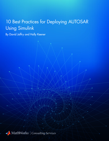
Main Concepts: Architecture The AUTOSAR Layered Architecture distinguishes on the highest abstractionlevel between three software layers:Application, Runtime Environment and Basic Software which run on a Microcontroller. 27
Main Concepts: Architecture The AUTOSAR Basic Software is divided in the layers: Services,ECU Abstraction, Microcontroller Abstraction and Complex Drivers. 28
Main Concepts: Architecture The applications functionality reside in the application layer. The only part of an AutoSar system that doesn’t consist of standardizedsoftware. Consists of SWCs (Software Components), the smallest part of a softwareapplication that has a specific functionality. Within AutoSar there are standard interfaces so that the components can be usedto build out a software applications. 29
Main Concepts: Architecture It is a standardized software without any own functionality that offers both hardware dependent andindependent services to higher layers. This is through API (Application Programming Interfaces).It makes the higher layers hardware independent.It has, for e.g., memory interfaces and interfaces to communication busses (LIN, CAN and FlexRay)Can be subdivided into the following types of services: Input/Output (I/O) Standardized access to sensors, actuators and ECU onboard peripherals Memory Standardized access to internal/external memory (non volatile memory) Communication Standardized access to: vehicle network systems, ECU onboard communicationsystems and ECU internal SW System Provision of standardizeable (operating system, timers, error memory) and ECU specific (ECUstate management, watchdog manager) services and library functions 30
Main Concepts: ArchitectureMCAL(MicrocontrollerAbstractionLayer) MCAL is the lowest software layer of the Basic Software It contains internal drivers, which are software modules with direct access tothe μC internal peripherals and memory mapped μC external devices. Consists of standardized functions that frees the hardware from the softwareand gives a standardized interface to Basic Software, making higher softwarelayers processor independent of abstracted μC and prevented from directlyaccessing the registers in the μC. MCAL handles the μC peripheral units and supplies processor-independentvalues to the Basic Software. 31
Main Concepts: ArchitectureEAL(ECUAbstractionLayer) The EAL interfaces the drivers of the MACL and also contains drivers forexternal devices. It offers an API for access to peripherals and devices regardless of theirlocation and their connection to the microcontroller (port pins, type ofinterface) Make higher layers independent of ECU hardware layout Its implementation properties, is μC independent and ECU hardwaredependent. For Upper Interface, it’s μC and ECU hardware independent 32
Main Concepts: Architecture The Complex Drivers Layer spans from the hardware to the RTE. Provide the possibility to integrate special purpose functionality, e.g.drivers for devices: which are not specified within AUTOSAR,with very high timing constrains orfor migration purposes etc. Its implementation and Upper Interface properties are: it might be anapplication, it’s μC and ECU hardware dependent. 33
Main Concepts: Architecture Services Layer is the highest layer of the Basic software which also applies for itsrelevance for the application software. While access to I/O signals is covered by theECU Abstraction Layer, it offers basic services for application and Basic Softwaremodules as: Operating system functionalityVehicle network communication and management servicesMemory services (NVRAM management), ECU state managementDiagnostic services (including UDS communication, error memory and fault treatment)Logical and temporal program flow monitoring (Wdg manager)Implementation Properties: mostly μC and ECU hardware independent. UpperInterface: μC and ECU hardware independent 34
Main Concepts: Architecture The Basic Software Layers are further divided into functional groups (11 main blocks plusComplex Drivers). Examples of Services are System, Memory and Communication Services. 35Example of Flow through layers: “NVRAM Manager” ensures the storage and maintenance ofnon-volatile data and is independent of the design of the ECU.
Main Concepts: Architecture The layered architecture has been further refined in the area of Basic Software andaround 80 modules have been defined.AUTOSAR extensibilityThe AUTOSAR SoftwareArchitecture is a generic approach: Standard modules can be extendedin functionality. Non-standard modules can beintegrated into AUTOSAR-basedsystems as Complex Drivers Further layers cannot be added. 36
Main Concepts: ArchitectureAUTOSAR SW-Cs (Software Components)They encapsulate an application which runs on the AUTOSAR infrastructure. And theyhave well-defined interfaces, which are described and standardized by SW-C Description(Provides a standard description format needed for the integration of the SW-C) Consist of Runnable Entities (or Runnables) procedures which contain the actualimplementation triggered cyclically or on event (e.g. data reception) Composite components for hierarchical design Ports Interface to other SW-Cs Other software components Application is divided into SW-Cs.There are three types of SW-C Atomic SW-C Composite SW-C Sensor/Actuator SW-C 37
Main Concepts: ArchitectureIntra‐ and Inter‐ECU Communication Ports are the interaction points of acomponent and they implement the interfaceaccording to the communication paradigm(client-server based). The communication layer in the basicsoftware is encapsulated and not visible atthe application layer.Communication is channeled via theAutoSar RTE (RunTime Environment) Implementation of Virtual Functional BusInterface between SW-Cs and Basic Software, therefore it frees SW-Cs from the hardware,BSW and from each other components.Every ECU in a AutoSar system must implement a RTEAll calls to basic software pass through the RTE, so all software components can communicatewithout being mapped to specific hardware or ECU.RTE uses the hardware MCAL (MicroController Abstraction Layer)Communication method : Send/Receive signals, Client/Server functionalityTriggering of runnables : Cyclically or On event 38
Main Concepts: ArchitectureThe Virtual Functional Bus (VFB ) The VFB is the sum of all communication mechanisms (and interfaces tothe basic software) provided by AUTOSAR on an abstract (technologyindependent) level. When the connections for a concrete system are defined,the VFB allows a virtual integration in an early development phase. The application components are linked andcommunicate through VFB. VFB is a visualization of all hardware andsystem services that the vehicle system supplies. Through VFB a software component doesn tneed to know which components it iscommunicating with and on which ECU thesecomponents are implemented. The VFB is implemented bythe AUTOSAR Runtime-Environment (RTE) and underlying Basic-SW layer. 39
Main Concepts: Architecture Communication between software componentsA SWC can communicate in two different ways: Client/server:Theclientinitiatesthecommunication and requests aservice from the serverThe client could be locked whileit is waiting for an answer fromthe server.The Client/server roles aredefined by who is initiating thecommunication and could beswitched. A SWC can at the same time actas both client and server indifferent communicationsSender/receiver: The sender expects no answer fromthe receiver as there will no be any. The sender is not blocked. The receiver decides on it s ownhow and when to act on theinformation. Theinterfacestructureisresponsible for the communication. The sender doesn t know Who the receiver is, if there are More than one receiver, or in What ECU the receiver is situated 40
Main Concepts: Architecture AUTOSAR Layered Architecture & ECU Software AUTOSARInterfaceStandardizedInterfaceAPI 3 PrivateInterfaces insideBasic eAPI AUTOSAR Runtime Environment (RTE)API 2VFB & RTErelevantAPI 1RTE edInterfaceBasic vers 41
Main Concepts: ArchitectureConclusion AUTOSAR harmonizes already existing basic softwaresolutions and closes gaps for a seamless basic softwarearchitecture. The decomposition of the AUTOSAR layeredarchitecture into some 80 modules has proven to befunctional and complete. AUTOSAR aims at finding the best solution for eachrequirement and not finding the highest commonmultiple. 42
Main Concepts: Methodology 43
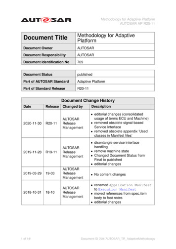
Main Concepts: MethodologyDerive E/E architecture from formaldescriptions of soft- and hard ware components Functional software is described formally interms of “software Components” (SW-C). Using “Software Component Descriptions”as input, the “Virtual Functional Bus” validatesthe interaction of all components and interfacesbefore software implementation. Mapping of “SW-C” to ECUs andconfiguration of basic software. The AUTOSAR Methodology supports thegeneration of an E/E architecture. 44
Main Concepts: MethodologyVirtual Integration Independent of hardwareIntroduction of HW Attributes Holistic viewof the entire system, both tangible and intangible 45ECU Configuration Run Time Environment Separationof system into its ECU (plus common infrastructure)
Main Concepts: Methodology AUTOSAR System - Design Process - Implementation Process 46
Main Concepts: Methodology Step 1a): Input Description (1 of 3) of SW-Componentsindependently of hardware 47
Main Concepts: Methodology Step 1b): Input Description (2 of 3) of hardware (ECU-ResourceDescriptions) independently of application software 48
Main Concepts: Methodology Step 1c): Input Description (3 of 3) of system (System-ConstraintDescription) 49
Main Concepts: Methodology Step 2: Distribution of SW-Component-Descriptions to all ECU with System Configuration on the basis of descriptions (not of implementations!)of SW Components, ECU-Resources and System-Description. Consideration of ECU-Resources available and constraints given in the System-Description. 50
Main Concepts: Methodology Step 3: ECU-Configuration by Generation of required configuration forAUTOSAR-Infrastructure per ECU 51
Main Concepts: Methodology Step 4: Generation of Software Executables Based on the configurationinformation for each ECU (example ECU1) 521) If need be, extract for ECU1 only2) SPAL: Standardized Peripheral Abstraction Layer
Main Concepts: Methodology 53
Main Concepts: MethodologyAutoSar Development process AutoSar has given a method for creating the systemarchitecture that starts in the design model.The model descriptions within AutoSar arestandardized to become tool independent.The descriptions have UML syntax (UnifiedModeling Language).The basic system descriptions are independent ofhow they are to be implemented.Necessary data are among others interface andhardware demands Standard interfaces aredescribed in XML (eXtendable Mark-up Language). 54
Main Concepts: MethodologyAutoSar MetaModel is modeled in UML is the backbone of the AutoSararchitecture definition. contains complete specification,how to model AUTOSAR systems Integrates methodology whichdefines activities and work-products Defines content of work-products, Formal descriptionof all the information that is produced or consumed inthe AUTOSAR methodology Has benefits as: The structure of the information can be clearly visualized and easily maintained.The consistency of the information and terminology isguaranteedUsing XML, a data exchange format can be generated automatically out of the MetaModel 55
Main Concepts: MethodologyExample 1: The Virtual Functional Bus (VFB ) Input to the System Design on an abstract level SW-Component-Description “get v()“ describes a function to acquire thecurrent vehicle speed and defines the necessary resources (such as memory,run-time and computing power requirements, etc.) Function “v warn()“ makes use of “get v()“ “ Virtual Integration“ by checking of Completeness of SW-Component-Descriptions (entirety of interconnections) Integrity/correctness of interfaces 56
Main Concepts: MethodologyExample 2: AutoSar Descriptions:To configure the system, input descriptions of all softwarecomponents, ECU resources and system constraints are necessary.Descriptionof Topology 57
Main Concepts: MethodologyExample 2: System ConfigurationMaps SW-C to ECUs and links interface connections to bus signals.SW-C to ECUsInterface Connectionsto Bus SignalsDescriptionof Mapping 58
Main Concepts: MethodologyConclusion The E/E system architecture can be described by meansof AUTOSAR. A methodology to integrate AUTOSAR softwaremodules has been designed. The meta model approach and the tool support forspecifying the AUTOSAR information model allowworking at the right level of abstraction. 59
Main Concepts: Application Interfaces 60
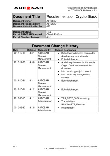
Main Concepts: Application Interfaces Standardized AUTOSAR interfaces approach will support HW independence,enable the standardization of SW components andensure the interoperability of functional SW-C (applications) from different sources. 61
Main Concepts: Application Interfaces AUTOSAR Application Interfaces Compositions under Consideration 62
Main Concepts: Application Interfaces To ease the re-use of SW-C across several OEMs. 63
Main Concepts: Application Interfaces Glance on Application Interfaces – Body DomainCmdWashing is the interface defined by following information: It is provided by the WiperWasherManager component through the[Washer]Activation port CmdWashing contains one data element command Command is of type t onoff which is a RecordType, whichdescribes a generic on/off information. 64
Main Concepts: Application Interfaces Major task: Conflict Resolution – Example Vehicle Speed 65
Main Concepts: Application InterfacesConclusion For several domains a subset of applicationinterfaces has been standardized to agreedlevels. It is a challenge to align standardization with thepace of application development. 66
Contents What is AUTOSAR Project Objectives & Benefits Use case “ Front-Light Management” AUTOSAR Main Concepts Architecture Methodology Application Interfaces Example of AUTOSAR System Conclusion 67
Use case “ Front-Light Management” 68
Use case “ Front-Light Management” 69
Use case “ Front-Light Management” Multiple ECUs 70
Use case “ Front-Light Management” Applying AUTOSAR 71
Example AUTOSAR System :Lighting System Software Component View 72
Example AUTOSAR System :Lighting System Virtual Functional Bus View 73
Example AUTOSAR System :Lighting System Mapped System 74
Example AUTOSAR System :Lighting System Basic Software Architecture 75
Contents What is AUTOSAR Project Objectives & Benefits Use case “ Front-Light Management” AUTOSAR Main Concepts Architecture Methodology Application Interfaces Example of AUTOSAR System Conclusion 76
ConclusionAUTOSAR Leverages model-based engineering of automotiveembedded software to whole systems. Enables management of the growing E/E complexity withrespect to technology and economics. Standardization itself is highly formalized and so supportsformal system development. Shifts implementation efforts to configuration. Pushes the paradigm shift from an ECU to a functionbased approach in automotive software development. Through interconnection of subsystems, new systemproperties emerge which have to be understood and 77controlled.
Further Information You can visit AutoSar website 78
Thank youAny questions . 79
Backup Slides 80
AUTOSAR –Implementation 81
AUTOSAR – Implementation (1 of 2) Implementation of functions independent on distribution on differentECU as communication will be done via ECU-individual AUTOSARRTE exclusivelyExample: view for one ECU 82
AUTOSAR – Implementation (2 of 2) The ability to transfer functions or SW modules (AutoSar Central Objective:Transferability) supports the following technical benefits Reuse of Intellectual Property (reuse of IP)Increase in design flexibilitySimplification of the integration taskReduction of SW development costsExample: viewfor two ECU 83
AUTOSAR Tools 84
AUTOSAR ToolsAutoSar is not manual - Scope of the standard support AutoSar MetaModel: 800 classes based of MOF with stereotypes extensions The standardization is based on exchanging XML at every steps Must be tooled: Manage (rights, configuration, changes,.)ImportDesignValidate 85
AUTOSAR Tools 86
AUTOSAR Builder ToolComponents AutoSar Requirement Management AUTOSAR Authoring Tool, AAT. ECU Extract. SWC Conformance Validation Tool, SCVT. Generic Configuration Editor, GCE. 87
AUTOSAR Builder ToolAuthoring Tool – SWCConformance ValidationApplication Level,Description and ValidationGCE,BSW Level,ConfigurationIn AutoSar ProcessSystem Configuration &ECU Extract, Descriptionand ValidationECU Configuration,Configuration 88
AUTOSAR Tools Integration of AUTOSAR Tools in AutoSar Process 89
AUTOSAR Tools 90
AutoSar BuilderPlatform Architecture Eclipse Plug-in mechanism Leverage on the mature existing tools in the market Open Framework adapted to System Engineering 91
Tool Architecture Starting Points: ECLIPSE 92
Technical infrastructure Model management UML/MOF/MDS (model driven schema) to EMFMulti resources support (files, database)Model validationModel extension, AUTOSAR profiles Model editing Tree view, forms, XML model of GUI, EMF methods generationGraphical editor, Topcased Collaborative support Svn integration Documentation Jet & Birt technologies,Creating jet code from the meta model Code Generation Jet External Tool integration 93
AUTOSAR – Drivers and Interfaces 94
AutoSar - DriversAn driver contains the functionality to control and accessan internal or an external device. Internal devices are located inside the microcontroller.Examples for internal devices are: Internal EEPROM Internal CAN controller Internal ADCA driver for an internal device is called internal driver and islocated in the MCAL “Microcontroller Abstraction Layer ”. 95
AutoSar - Drivers External devices are located on the ECU hardware outside themicrocontroller. Examples for external devices are: External EEPROM External watchdog External flashA driver for an external device is called external driver and is located in theEAL “ECU Abstraction Layer”. It accesses the external device via drivers of theMCAL. This way also components integrated in SBCs (System Basis Chips) liketransceivers and watchdogs are supported by AUTOSAR.Example: a driver for an external EEPROM with SPI interface accesses the externalEEPROM via the handler/driver for the SPI bus.Exception: The drivers for memory mapped external devices (e.g. external flashmemory) may access the microcontroller directly. Those external drivers arelocated in the MCAL because they are microcontroller dependent. 96
AutoSar - Interface An Interface (interface module) contains the functionality to abstractfrom modules which are architecturally placed below them. E.g., aninterface module which abstracts from the hardware realization of aspecific device. It provides a generic API to access a specific type ofdevice independent on the number of existing devices of that type andindependent on the hardware realization of the different devices. The interface does not change the content of the data. In general, interfaces are located in the ECU Abstraction Layer. Example: an interface for a CAN communication system provides ageneric API to access CAN communication networks independent onthe number of CAN Controllers within an ECU and independent ofthe hardware realization (on chip, off chip). 97
AutoSar – Handler and ManagerA handler Is a specific interface which controls the concurrent, multiple andasynchronous access of one or multiple clients to one or more drivers. i.e.it performs buffering, queuing, arbitration, multiplexing. Does not change the content of the data. Functionality is often incorporated in the driver or interface (e.g.SPIHandlerDriver, ADC Driver).A manager offers specific services for multiple clients. It is needed in all cases wherepure handler functionality is not enough to abstract from multiple clients. Besides handler functionality, a manager can evaluate and change or adaptthe content of the data. In general, managers are located in the Services LayerExample: The NVRAM manager manages the concurrent access to internal and/orexternal memory devices like flash and EEPROM memory. It also performsdistributed and reliable data storage, data checking, provision of default values etc. 98
AutoSar - LibrariesLibraries are a collection of functions for related purposes. They: Can be called by BSW modules (that including the RTE), SW-Cs,libraries or integration code run in the context of the caller in the same protection environment can only call libraries are re-entrant do not have internal states do not require any initialization are synchronous, i.e. they donot have wait points 99
AUTOSAR - Methodology andApplication InterfacesUse cases 100
Sensor/Actuator AUTOSAR SW-CThe Sensor/Actuator AUTOSAR Software Component is a specifictype of AUTOSAR Software Component for sensor evaluation andactuator control. Though not belonging to the AUTOSAR BasicSoftware, it is described here due to its strong relationship to localsignals. It has been decided to locate the Sensor/Actuator SWComponents above the RTE for integration reasons (standardizedinterface implementation and interface description). Because of theirstrong interaction with raw local signals, relocatability is restricted.Task:Provide an abstraction from the specific physical properties of hardwaresensors and actuators, which are connected to an ECU.Properties:Implementation: μC and ECU HW independent, sensor and actuatordependent 101
Main Concepts: Methodology AUTOSAR – Assignme
AUTOSAR (AUTomotive Open System ARchitecture) Middle-ware and system-level standard, Jointly-developed by automobile manufacturers, electronics and software suppliers and tool vendors and developers. More than 100 member companies Homepage : www.autosar.org Motto: "Cooperate on standards - compete on implementation" 4