Transcription
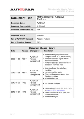
User-friendly Configuration of AUTOSAR ECUs withSpecialized Software ToolsThe simple CAN ECU is a thing of the past. Now, a typical ECU utilizes many functions of the AUTOSAR basic softwareto perform its complex tasks. However, the more functions there are, the more difficult and extensive the configurationprocess is too. Without tool support, developers would be lost.Three factors affect the complexity of ECU configuration: More standardizationA large share of ECU software has now been standard-controller Abstraction Layer modules (TIER2-MCAL).This means that more coordination effort is requiredinitially in the configuration process.ized as basic software by means of AUTOSAR. However,the AUTOSAR principle “configuration instead of imple-How do Software Tools Help here?mentation” forces developers to create a consistentThe AUTOSAR standard continues to develop in a highly dy-overall configuration from the start. There are nonamic manner. There are changes with each new release: the provisions for making corrections directly in the code. More functionsmodules are defined. All of these modules come with theirNew microcontrollers with multiple cores and memoryown configuration parameters. However, the AUTOSARprotection features and new networks such as Ethernetconfiguration approach is fundamentally able to handlehave increased the scope of the basic software, andthis dynamism with its formally described module struc-therefore configuration needs. New cooperation models1functionality of existing BSW modules is changed and newtures and parameters. This makes it possible to quickly andeasily define the Basic Software Module DescriptionsThe AUTOSAR methodology encourages new roles in the(BSWMD) contained in the delivered BSW. At first, this for-development process (Figure 1). In addition to themal method sounds enticing as an approach for tools: thesupplier of the AUTOSAR basic software (TIER2-BSW),tool company would develop a generic tool with a reason-there are also suppliers of the application softwareable amount of effort, and then all parameters could becomponents (TIER2-SWC) and hardware-related Micro-individually configured – those parameters that are known
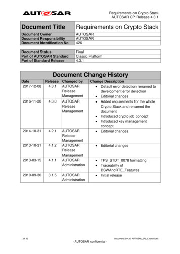
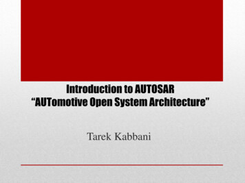
today as well as all future parameters. However, no onedefined configuration of arbitration rules, logical expres-would want to configure the thousands of necessary pa-sions and actions, for reacting to mode changes in otherrameters in such an editor without further support.BSW modules or for requesting mode changes itself. Anassistance function now helps to configure the BswM suchSpecific Editors and Assistance Functionsthat it behaves similarly to the relatively easy to handleThere are a number of approaches for developing a soft-ECU State Manager (EcuM) from AUTOSAR 3.ware tool that can simplify this work. A specially developededitor displays the relationships between parameters andDeriving Parameters from the System Descriptionsimplifies the configuration process, e.g. by bulk operations.Configuration of the communication modules for CAN, LIN,In addition, such an editor can group parameters themati-FlexRay or Ethernet must match the system descriptioncally – even extending beyond module boundaries. The edi-that originates from the OEM. AUTOSAR provides for der-tor’s graphic views make it easier to understand the com-ivation of a basic configuration of the modules (the Baseplex configuration. Such tools are helpful and necessary inEcuC) from an ECU-specific extract of the system descrip-all domains of the basic software such as communication,tion (System Extract). In practice, however, the situation ismode management, diagnostics, memory managementsomewhat more complicated (Figure 3): AUTOSAR has de-and I/O. When using an editor in the area of memory do-fined a standard format for the system descriptions. But inmains, for example, the developer can rather simply insertaddition to this format, OEMs also use the traditional DBC,a memory block, which is then consistently configured inLDF and FIBEX formats. Furthermore, the TIER1 supplierthe non-volatile RAM manager (NvM) as well as in the flashmight use its own system descriptions, e.g. for private CANEEPROM emulation (Fee). It is also very easy to estimatebuses within the ECU or for LIN buses that connect sensorsthe overhead from the ratio of user data to block size in awith the ECU. The software tool must therefore identify allgraphic display (Figure 2).possible types of input data, convert traditional formats byAssistance functions are also helpful in the configurationsuitable preprocessing methods and generate ECU-specificprocess. When the developer changes a parameter, for ex-extracts. It must also be possible to merge multiple, sepa-ample, other parameters that depend on it are automati-rate system descriptions into a common description. Onlycally corrected by a rules system. For more complex tasks,then is it possible to generate the Base EcuC.such as mapping runnable entities to operating systemSimilar considerations apply to the diagnostic modules. Thetasks, assistants may be of help: The developer can per-configuration of the modules must match the ODX specifi-form tasks like selecting runnable entities of the SWCscation of the ECU. Therefore, the ODX file must also be in-based on similar trigger conditions, assign a task and final-cluded into the Base EcuC.ly define the execution sequence within the task.Sometimes the TIER1 also has a standard configuration forAnother example from the mode management domain:its projects that is available directly in EcuC format. TheseThe BswM module in AUTOSAR 4 permits completely user- configuration elements should also be contained in theBase EcuC. The BSWMD files that the tool needs in orderto check the configuration can originate from varioussources. They are either provided by the TIER2-BSW supplier,Figure 1: Roles in an AUTOSAR development projectFigure 2: Advanced views simplify the ECU configuring2
or they might be supplied by the microcontroller manufac-scription and the delivery date of the ECU is very short. Aturer so that they match the MCAL modules.tool must therefore be able to update the configurationFinally, the SWCs might be contained in the system extractwith the new input data as automatically as possible. Awhich the OEM provides to its suppliers. According to theproject update function can do this by generating a newAUTOSAR 4 method, the system extract is first used toBase EcuC, and by updating the actual configuration to thegenerate an ECU extract, which represents a flat perspec-new Base EcuC.tive of the SWCs.But what happens when there are errors in the system de-Afterwards, for example, the ECU extract is extended toscription? Even when the problems have been clarified withinclude other SWCs which might be provided by externalthe OEM, a corrected system description is usually notsuppliers (TIER2-SWC).available immediately. In such cases, the ECU developerUsing the ECU Extracts and the Base EcuC, the ECU devel-might want to intentionally ignore some of the derived pa-oper creates the overall configuration of the BSW and RTErameters and overwrite them with other values. This is a(Runtime Environment). Here, the tool should treat thoseway to correct the error directly in the ECU configuration.parameters taken from the Base EcuC as write-protectedSince such a deviation is always critical, the ECU developerto avoid deviations from the system extract.should be able to explicitly set the parameter status as “user-defined” in the tool. As long as the parameter is inProject Updatethis status, the tool may not overwrite its value when per-Over the life of the project, the developer continually re-forming a project update. Only when the ECU developerceives updated input data. Typically, these updates arriveremoves the status “user-defined”, the parameter adoptsat different points in time and with varying frequency. Thethe derived value.OEM distributes new system descriptions according to theThe tool also helps in coordination between the ECU devel-specific milestones of vehicle development, while the diag-oper and the OEM, e.g. by generating a report on overwrit-nostic description is typically updated much more frequent-ten parameters.ly. Often, the time span between receiving the system de-Figure 3: Workflow for creatingand updating an ECU configuration based on the example ofDaVinci Configurator Pro fromVector3
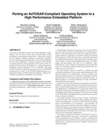
User-friendly Configuration of AUTOSAR ECUs with Specialized Software ToolsFigure 4: Development of “vertical” ECU functions“Merge” Function for Multiple Developers Working in Parallel Figure 5: Diff/Merge support in DaVinci Configurator ProEven on smaller ECU projects, multiple developers are always working on the project simultaneously. If competencies are clearly defined (e.g. “Colleague xy is always responsible for the operating system.”), then it is possible to avoidwould be of help here (Figure 5). Ideally, the user could viewmaking parallel changes to the same module or to thethe differences directly in the same editors with which thesame SWC. Typically, however, the developers are workinguser created the configuration. Then the user would feel “atin parallel, and they develop ECU functions that run verti-home” and would not have to work with a separate toolcally through all of the architecture layers of the ECU soft-with different, unfamiliar view of the data.ware (Figure 4). In the times of manual C-coding, the inte-Nonetheless, the following rule of thumb applies: The fewergrator would then merge the different code branches onthe changes that need to be merged the better. Massivetextual level. With AUTOSAR, however, this would meanchanges to the configuration might result from a projectthat the integrator would have to merge XML files inupdate to a new communications matrix (C-matrix), for AUTOSAR format that could be many megabytes in size. Itexample. Therefore, the following practical procedure is would be practically impossible to compare or merge anrecommended: Starting from an integration milestoneAUTOSAR configuration using general XML tools. TheMS0, the feature developers each do their developmentstructure of the file and the many references within the filework on a separate branch (Figure 6). The branches areare much too complicated for that.merged, one after another, in the main branch – possibly inOnly an AUTOSAR- tool that clearly displays the differencesseveral intermediate steps (MS1 to MS3). Only then can thein the AUTOSAR configuration and offers merge optionsintegrator update a project to a new C-Matrix (MS4).Figure 6: Working on the sameECU configuration in parallel4
Afterwards, new branches can be added and functions developed that match the new C-Matrix. All of this can besupported by a Configuration Management (CM) system,which also manages the implementation files of the SWCs.Available ToolsThe tool DaVinci Configurator Pro from Vector already enablesthe described working method. Soon, DaVinci ConfiguratorPro will also permit the creation of configuration variants,which can be dynamically switched in the ECU. They are alsoknown as Post-Build Selectable Variants. Here too it is important to intelligently implement the available AUTOSARconcepts in tool functions. Then the developer gets furthervaluable support in the development of AUTOSAR projects.Translation of a German publication in Elektronik automotive,Issue 4 / 2014Image rights:Vector Informatik GmbHLinks:Vector AUTOSAR Solution: www.vector.com/autosarMatthias Wernicke (Dipl.-Ing. (FH))After completing his studies in Industrial Electronics at the University of Applied Science at Ulm, he was employed at theDaimler Research Institute in Ulm for four years. Since early2000, he has been employed at Vector Informatik in Stuttgartworking on the development of methods and tools for designingdistributed electronic functions in motor vehicles. Today, he isresponsible for product management of the DaVinci AUTOSARtools.5
User-friendly Configuration of AUTOSAR ECUs with Specialized Software Tools The simple CAN ECU is a thing of the past. Now, a typical ECU utilizes many functions of the AUTOSAR basic software to perform its complex tasks. However, the more functions there are, the more difficult and extensive the configuration process is too.