Transcription
ODOT Inspector’s ManualFOREWORDThe 2014 Inspector’s Manual is a revision of the 2001 manual. The 2014 version includesdirection from the Specification Owners/Technical Experts on what they view as criticalinspection areas for a given specification. The Inspector’s Manual is a work in progress as welook to further enhance the materials with input from all users including inspectors.Along with the manual text, additional resources are included: General Guidance Section provided as a tool for those new to ODOT constructioninspection. The introduction sections we provide in the classroom training are condensed intothis section. The information focuses on navigating the specifications, special provisions,plans and other resources in general. The General Guidance section while directed to newInspectors is also a tool for experienced Inspectors as a review for the General ConstructionInspector certification exam. Inspector Manual Tables organized by specification including guidelines for inspecting anddocumenting work provided in a tabular format. Forms List organized by Specification with a hot link to the on-line forms. ODOT Checklists for Sections 00200’s through 01100’s as available. Not every section hasa checklist available but we have included what is available through ODOT. Non-Field Tested Materials Guide Flowchart as a basic reference to understanding howthe Guide is used. An example is provided to demonstrate the process. Documentation Information with hot links to the Construction Manual. We guessed that notevery Inspector has a Construction Manual on his/her desk so we provided links whichinclude examples of properly completed forms. The key documentation sections include:Dailies, Quality and Quantity. Reading Slope Stakes Reference to understand the basics of what is written on a slopestake.We foresee this document as a work in progress and welcome any suggestions to improve itsusefulness. If you have ideas for improvement, please contact us at:Liz Hunt, Inspection QA Program CoordinatorElizabeth.A.Hunt@odot.state.or.usJason Cieslak, Inspection QA SpecialistJason.Cieslak@odot.state.or.us
INSERT TABGeneral Guidance
ODOT Quality Assurance Materials & InspectionInspector’s ManualGeneral Construction InspectorGeneral GuidanceTable of ContentsRole of Construction Inspector .3Documentation .4Inspector Resources .4Order of Precedence .5Specifications and Plans .6Navigating the Specifications .7Navigating the Plans .8Plan Set Organization .8Basic Plan Reading . 10Select Plan Components . 10Standard Drawings. 18Summary Table . 18Summary of General Inspection Resources . 19Review: Putting It All Together. 20General Inspection Navigation: Where to Start . 21Standard Specifications Review. 21Non-Field Tested Materials Guide (NFTMG). 23Qualified Products List (QPL) . 23General Guidance1May 2014
ODOT Quality Assurance Materials & InspectionGeneral GuidanceInspector’s Manual2May 2014
ODOT Quality Assurance Materials & InspectionInspector’s ManualGeneral GuidanceRole of Construction InspectorThe construction inspector has the toughest job in construction. The Inspector has theresponsibility and authority to point out deviations from specifications, but has nocorresponding authority to approve changes, even though they might be minor. TheInspector’s function begins and ends with seeing that construction operations producethe results called for in the plans and specifications. If an Inspector has the quality offirmness coupled with patience, and judgment inherent with a desire to be correct butpractical, then they will fulfill their intended function on the construction team.Inspectors must work constantly to achieve a high standard of excellence in theadministration and quality control of constructionprojects. Each Inspector has the responsibility toSS 00150.01 Inspector’sperform in such a manner that their personal goals andAuthority and Duties includethe owner/designer goals are in harmony. Since anthe responsibility to orallyInspector is isolated from immediate supervisoryresources and guidance much of the time, they must bereject defective materials able and comfortable in making many individualjudgments throughout the workday affecting the qualityof construction. The Inspector represents the owner at the site of work and isempowered to enforce the provision of the Contract. The Inspector is authorized to rejectmaterials and workmanship not in conformance with contract requirements.The Inspector must be mature, confident, patient, meticulous in duties, and be a personof integrity who also possesses good judgment. There are innumerable attributes thatmake up a good Inspector. An unknown author once described an Inspector best bydefining what they are not: An Inspector is NOT a designer, although they must be able to read plans andspeak with designers. An Inspector is NOT a surveyor, although they must understand surveyingprinciples. An Inspector is NOT a superintendent, although they must know construction andgood planning. An Inspector is NOT a policeman, although they must secure compliance with theContract. An Inspector is NOT a lawyer, although they must understand and enforceContract Law. An Inspector is NOT a carpenter or other tradesman, although they mustrecognize qualified people. An Inspector is NOT an accountant, although they must be able to keep detailedrecords.General Guidance3May 2014
ODOT Quality Assurance Materials & InspectionInspector’s ManualThe ideal Inspector must have desire, reasonableness, firmness, good judgment,knowledge, and courtesy. Their interactions with construction crews must be friendly andfirm without familiarity, and must be conducted with the skill of a diplomat. Thefundamental requirements for a good Inspector are: Knowledge – It is of paramount importance that the Inspector has knowledge ofthe work inspected. Common Sense – The means to synchronize knowledge and specifications; applyone to the other. Observation – see with eyes as well as considered thought about the imageobserved. Physical Tools – Measuring devices, testing equipment, notebook, pencil; and theability to use them. Courtesy – Valid criticism; how one says it can drastically effect how one receivesit.DocumentationThe importance of documentation on a construction project cannot be stressed enough.It is critical for recording quantities and quality of materials placed which allows thecontractor to be paid and the Agency confirmation of quality. It is also critical to provide ahistory of how the project was built for future reference like for making adjustments in thecontract time. In addition, it could be important for providing information for the Agency inresolving a dispute. The ODOT Construction Manual has a complete chapter on ProjectRecords. To assist the Inspector, excerpts from the chapter are included in the GeneralInspection Training Manual under the documentation tab.Inspector ResourcesInspectors have many resources available to help them perform their jobduties effectively. The most important construction resources are theproject plans, special provisions and Oregon Standard Specifications,Volumes 1 and 2. These resources will be discussed in later sections.Other important resources that may be referred to in the plans orspecifications include: The Manual of Field Test Procedures (Brown Book): The Brown Book appliesto testing done at the jobsite like compaction and/or materials sampled at thejobsite like aggregate or concrete. The manual provides several sections includinga description of the ODOT Quality Assurance Program; testing requirements andtest methods for various materials used; report forms and examples; and TheField Tested Materials Acceptance Guide for Type D or E Projects Only.The Field Tested Materials Acceptance Guide for Type D or E Projects section isGeneral Guidance4May 2014
ODOT Quality Assurance Materials & InspectionInspector’s Manualimportant for inspectors to understand as it details what tests are to be performed;who is to perform them and how frequently they must be performed. While theQuality Control Compliance Specialist (QCCS) is responsible for monitoring thetesting, oftentimes it is the inspector’s responsibility to notify the QCCS whentesting will be needed. Also, it is important to be aware that the testing isoccurring and that where possible, test results are documented in the Inspector’sDaily Report. The Non-Field Tested Materials Guide: Non-field tested materials include itemslike sediment barrier, geotextile, steel piling and bolts. The Guide provides a tableof the materials covered along with a list of the required acceptance (quality)documents. A flow chart with guidance on how to use the NFTMG is included inthe NFTMG tab in the General Construction Inspection Training Manual. For morenavigational tips, refer to the Review Section of this Supplement. Qualified Products List: The "QUALIFIED PRODUCTS LIST" (QPL) is acomprehensive list of all finished products which have been evaluated and/orused by the Oregon DOT. Because there are items that are used over and overon projects, it makes sense to maintain a list of products that have been used anddon’t need to be re-evaluated every time they are to be incorporated. If an item isrequired to be taken from the QPL, the Non-Field Tested Materials Guide willprovide direction to the QPL. For more navigational tips, refer to the ReviewSection of this Supplement. Construction Manual: An additional useful publication isthe Construction Manual which you may find in the officebound in an orange binder. The Manual providesbackground and procedural guidance for Volume 1 of theOregon Standard Specifications. Chapter 12, ProjectRecords is of particular interest to an inspector as itprovides guidance on preparing Daily Reports/Diariesand Quality Documentation, etc.Order of PrecedenceMany documents may be referenced for a project and sometimes conflicting informationis included. For example, the project plans may call out for a given dimension and thespecial provisions have something different. To reconcile the differences, an order ofprecedence has been established. The order of precedence is listed in Volume 1 of theODOT Standard Specifications, under 00150.10(a).General Guidance5May 2014
ODOT Quality Assurance Materials & InspectionInspector’s ManualThe order is presented in the pyramid to the left indicating that the most general projectdocument which is also, in most cases the oldest, has the least precedence. As youmove up the pyramid, thedocuments become increasinglymore project specific and morecurrent with contract changeorders taking precedence overall other documents. Note thatan order of precedence formaterial specifications and testmethods also is established andcan be found in section00165.20.Specifications and PlansAs previously mentioned, the critical documents to have available when inspecting aproject include the Special Provisions, Standard Specifications and Plans. The plansprovide the requirements for constructing a project including the location and dimensionsof all features that will be incorporated which make them unique for each project. Toanswer questions like how deep to install a feature or which side of the highway to placea pipe, the answers are going to be found in the plans. Answers to questions about thescope of the work, the construction limitations, the necessary equipment are going to befound in the specifications.SpecificationsThe Oregon Standard Specifications forConstruction provide the basic guidelines forconstructing a project. The StandardSpecifications are printed about every six yearsso there are areas that require updates astechnology changes or best practices areidentified. To document the changes, ODOTposts boiler plate special provisions that includethe recent changes for a given specification. When a project is developed, the standardspecifications and/or boiler plate specifications are compiled and modified as neededand incorporated into the special provisions. From an inspector’s perspective, the firstcheck on a specification should be to the special provisions which may or may not referback to the standard specifications.General Guidance6May 2014
ODOT Quality Assurance Materials & InspectionInspector’s ManualNavigating the SpecificationsThe Oregon Standard Specifications for Construction include two volumes. Volume 1contains Part 00100 and covers the defined terms, the bidding process and contractualrelationships. Essentially, it covers the rules of the contract between the Agency and theContractor. Volume 2 contains Parts 00200 through 03000 which describe the actualdetails of how a design feature is going to be constructed.Believe it or not, ODOT standardspecifications and special provisions(Sections 00200 through 01999)subsections are organized in the sameway. The figure to the right shows thegeneral organization of the subsectionsEach specification will have uniquesubsections like scope, labor,construction, etc. but the individualsubsections will always be listed underX.00 for Scope; X.30 for Labor and X.40for construction, etc. For example, if thequestion was what type of labor isrequired for Pipe Lining? it could beanswered by looking under 00410.30Specification Organization(Pipe Lining, Personnel Qualifications). Ifthe question was, “How is pipe lining measured?” The answer could be found byreferencing 00410.80 (Pipe Lining, Measurement).Sometimes, however, moreeffort is required. Navigating thespecifications could be as easyas referring to the table ofcontents and/or index. The keyto finding answers in thespecifications is to not give up –and be sure to read the entiresubsection. The flow chart isprovided as a tool to assist insearching the specifications. Formore navigational tips, refer tothe Review Section of thisSupplement.Searching for a SpecificationSpecial Provisions and Schedule of ItemsAn alternate method to find a specification is to refer to the special provisions. If thequestion is specific to a construction project, there should be a related bid item. Thespecial provisions include a Schedule of Items toward the end of the document, whichlists all of the project bid items with a specification reference. Hence, if the bid item canbe found then the specification can be found.General Guidance7May 2014
ODOT Quality Assurance Materials & InspectionInspector’s ManualThe Schedule of Items is arranged by sections which are logically sequenced fromactivities that take place at the beginning of construction to those that take place later ina project. In the class project, the Schedule of Items has ten sections including Section0001: Temporary Features and Appurtenances, Section 0002: Roadwork, Section 0003:Drainage and Sewers, etc. By narrowing the area of construction, a bid item can befound. A snapshot of Section 0006 Roadwork is shown below:Items number 560, 570, 580 and 590 reference 0745 which means that SpecialProvision Section 00745 Hot Mix Asphalt Concrete includes multiple pay items. Sincehot mix asphalt concrete paving can include many materials, each material listed isrequired to be measured and paid for separately.Navigating the PlansODOT plans include the specific locations, dimensions, drawings, and installation notesfor constructing the features on the project. The plans have consistent layouts that makethem easy to navigate. The table below provides a description of what information isprovided in a plan set by sheet number.Plan Set OrganizationPagePage DescriptionGeneral GuidanceInformation Included8May 2014
ODOT Quality Assurance Materials & InspectionPageInspector’s ManualPage DescriptionInformation Included1Title page Project limits, location Work activities (below project name)1A’s Index of Sheets Index of StandardDrawingsTypical Sections (listedby line and station) List of project specific drawings Standard drawings used specific to the project2B’sDetails used specific tothe project (modifiedstandard drawings) 2C’sTraffic Control Plans Details of sign placements Detour Traffic control plans (including cross sections)2D’sPipe Data Sheets 3’sGeneral Construction(shown by line andstation) General construction alignment General construction profile including excavation and fill estimates Drainage and utilitiesG’sGeo/Hydro/Environmental SheetsDrawingNumbersFrom BridgeDrawingNumbersFrom Traffic2A’s Roadway dimensions Widening dimensions Pavement thicknesses (aggregate base, HMAC base course,HMAC wearing course) HMAC mix typeConstruction information that could be needed at various locations.HMAC pavement repairsSubgrade stabilizationMiscellaneousSize and length of pipePipe UsePipe materialList of standard drawings related to pipe installation Erosion Control (GA-) Geotechnical Data (GB-) Retaining Walls (GC-) Sound Walls (GD-) Culverts (GE-) Fish Passage (GF-) Temporary Water Management (GG-) Bank Protection (GH-) Stormwater (GJ-) Landslide Correction (GK-) HazMat (GL-) Material source/Disposal Sites (GM-) Roadside Development (GN-) Waterway Enhancement (GP-) Rockfall Mitigation (GQ-)See plan index (Sheet 1A) for what is included.See plan index (Sheet 1A) for what is included. Most common sheetsinclude: Permanent Pavement Markings Permanent SigningGeneral Guidance9May 2014
ODOT Quality Assurance Materials & InspectionPageInspector’s ManualPage DescriptionInformation Included Illumination Plans Signal PlansBasic Plan ReadingConstruction plans include tabular information as well as graphical information. It isimportant to understand what the graphical depictions are in order to match up theinformation to the field. The fundamental graphical views are discussed here asbackground.Common views presented include the plan, elevation, and cross section view. The viewsare presented below using a four wheel motorized vehicle, courtesy of NHI Course134108 Plan Reading. For more information and detail, check out the NHI website foron-line training modules.The Plan View is a snapshot of a feature lookingdirectly down on it. The elevation is looking at a featurestraight on from one side or the back. The crosssection view can either be a slice across the side or themiddle as shown in the example to the right.In the cross section view to the right, a section hasbeen “sliced” away and the inside of the armored car isseen from the side. The inside of the car is also shown.In a drawing, dotted lines show parts not seen, such asthe tires or other parts that cannot be seen.Select Plan ComponentsAlignmentGeneral Guidance10May 2014
ODOT Quality Assurance Materials & InspectionInspector’s ManualWhen building a project, oftentimes more than one roadway segment includes workactivities. Each roadway segment is an alignment with a unique designation. Thedesignation may apply to an off-ramp or an adjoining street or separate alignments ondivided highways. For example, for a project constructed in Lane County for the BeltlineHighway, one alignment was designated BL for Belt Line while another alignment wasdesignated EBO for East Bound Off-ramp. Information in the plan set will be tied to analignment which can typically be found on the Title Sheet.StationingStationing is used to identify the beginning and ending of a given section on analignment or to identify a point where a feature is located. Stationing is designatedcontinuously from a starting point of 0 00. Each 100 feet increases the stationing by oneso that the stationing would run 1 00 to 2 00, etc. The 2 00 indicates that the point is200 feet from a starting point. If the point was 3005 feet from a starting point, the stationwould be 30 05.Stationing is marked along thecenterline of a given alignment asshown in the example. Stationingallows the distance between anytwo points to be determined. Forexample, to determine thedistance between Sta. EBO104 00 to Sta EBO 105 07.5,remove the “ ” in the stations andsubtract the higher station fromthe lower station: 10507.510400 107.5 feet.Image courtesy of NHI Course 134108General Guidance11May 2014
ODOT Quality Assurance Materials & InspectionInspector’s ManualWhen a particular feature is located along an alignment, a station will be provided withan offset distance designated either left or right. To determine the orientation of left andright side of road, picture yourself standing on thebeginning station looking ahead with the stationingincreasing. From that perspective, the right offset is toyour right and the left is to the left side of the roadway.Example of construction note withdirection Rt. designated.Typical Sections – GeneralTypical sections are cross sectional views that define the configuration of a proposedroadway at right angles to the centerline. Typical sections show the width, thickness, anddescriptions of the surfacing courses, as well as, the geometrics of the graded roadbed,side ditches, and side slopes. Typical sections will have the alignment designation andthe beginning and ending stations to show where that typical section is used and what isgoing on between those stations.Typical Section ComponentsTypical section requirements differ from project to project; however, all typical sectionsshare the same general components as shown in the figure above and described below. Median – The portion of a divided highway separating the traveled way for trafficin opposing directions. The principal functions of a median are to separateopposing traffic, provide a recovery area for out-of-control vehicles, provide astopping area in case of emergencies, allow space for speed changes, storage ofleft turning vehicles, minimize headlight glare, and to provide width for futurelanes. Profile Grade – A control point referring to the design profile for maintainingproper roadbed grade. Traveled Way – The area of roadway surface designed for vehicular movement(traffic lanes) between fog lines.General Guidance12May 2014
ODOT Quality Assurance Materials & InspectionInspector’s Manual Paved Shoulder – The portion of the roadway contiguous with the traveled wayfor emergency use recovery of out of control vehicles, accommodation ofpedestrians, bicyclists, and stopped vehicles, and for lateral support of subbaserock, base rock, and surface courses. Rock Shoulder – The shoulder created with rock drainage material used to coverthe ends of the surface courses and bases, and for additional area for recovery ofout of control vehicles. Curb – Edging along a street or roadway. Foreslope – Negative slope of drainage channel. Slope must accommodaterecovery of out of control vehicles. Backslope – Positive slope of drainage channel. Slope must accommodaterecovery of out of control vehicles.Typical Sections – ODOTTypical sections are used in most contract plans developed in the ODOT format. Theyare an important part of the plans because they show a detailed cross-sectional view ofthe work to be done. Therefore, each subsequent typical section or partial sectionrepresents a change or variation in the design.Typical Sections are listed in the following order: Mainline Frontage Roads or Intersecting Alignments RampsCheck the Stationing on the typical sections to be sure that the entire project isrepresented with no gaps or overlaps. When looking for a feature, make sure to verifythe proper alignment.Working with the typical section above, many things can be determined including: This section is applicable for 5800 - 5668 132 feet The pavement section includes a subgrade geotextile, 15″ of aggregate base, 6″of HMAC for base (Level 3 (mix type) dense mix (aggregate gradation) with ¾″aggregate (largest aggregate size)), and 2″ of HMAC for a wearing course (Level4 open mix with ¾″ aggregate) The side slope is to be constructed at 1:2 which represents 1 vertical to 2horizontal (listed as a separate note in the plans).General Guidance13May 2014
ODOT Quality Assurance Materials & InspectionInspector’s ManualODOT Typical SectionTaper SectionsThe typical section above includes taper sections since the road width is changing overthe 132 feet. At the beginning station for the typical section, the first taper width listed isused. At the ending station for the typical section, the final taper width listed is used. Forthe section above the taper widths would be: 2' at STA. WOF 56 68 12' at STA. WOF 58 00Pipe Data SheetsPipe data sheets include a wealth of information that can easily be overlooked unlesseach section is carefully reviewed. Included in the data sheets are the sheet number thatprovides the location of the pipe installation, the pipe length, diameter, type, use, andappurtenances like attached manholes or inlets. The sheet also includes a list ofstandard drawings that are needed for the project. Examples of information included inthe pipe data sheets are shown in the figures.General Guidance14May 2014
ODOT Quality Assurance Materials & InspectionInspector’s ManualExample Pipe Data Sheet InformationGeneral Construction InformationAfter the pipe data sheet, the plans include general construction information. The sheetsare bundled by station for easy navigation. The first sheet in the set is GeneralConstruction sometimes followed by Drainage and Utilities and then the Profile Sheet,The Profile Sheet may include information on manhole and inlet elevations, grades, andexcavation and embankment quantities. For example, general construction informationfrom station 1 00 to 2 00, would start on sheet 3, Sheet 3A would include drainage andutilities and 3B would be the profile. Station 2 00 to 3 00 would be covered by sheets 4through 4B. Other sheets could be included in the packet like the alignment plan, detourinformation or removal plans. The other sheets would be linked to the GeneralConstruction, Drainage and Utilities and Profile sheets with the same number followedby the next letter in the alphabet. (See Plan Set Organization table.)General Guidance15May 2014
ODOT Quality Assurance Materials & InspectionInspector’s ManualPlan ViewThe plan views for a project are included on the Construction Plan Sheets. Thestationing on the sheets typically increases from left to right. The top of the sheet (abovethe centerline) is left to the centerline and the bottom of the sheet (below the centerline)is right. Installation location information for features like signs, fencing, guardrail,delineators, and/or guardrail is included.Construction Plan SheetProfile ViewThe profile view is like a longitudinal cross section of the road. Elevation, in feet is listedon the left and right hand sides of the section with station listed underneath the section.The profile grade is drawn on the scaled profile at an elevation taken at a point on thehighway, usually at the centerline. The original ground line depicts the land beforegrading. If the original ground is excavated to match the profile grade, the section is acut area. If the original ground is below the profile grade line, fill material will be requiredto bring it up to grade.Information included on the profile sheet includes the elevation of the original ground,finished grade, subgrade elevation, curve information and grades. The sheet may alsoinclude excavation and embankment quantities, as shown below.General Guidance16May 2014
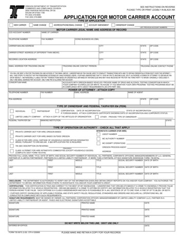
ODOT Quality Assurance Materials & InspectionInspector’s ManualConstruction Profile SheetSigningPermanent signing sheets fall within the broad category of traffic. The sheets includeinformation on the location of the sign, whether it is to be removed or left in place, thelocation of new signs and the type of sign support all referenced to a sign number. Theactual signs are located on a separate plan sheet that shows new signs indicated withsolid borders and existing signs indicated with broken borders.Also included with the sign sheets, are a sign and post data table. The table includes areference back to the sign number, the size, legend type and the post support type. Thesign and post data table references the Oregon Standard Drawings needed for aparticular sign construction. Like the pipe data sheet, the signing plan sheets are full ofinformation and careful attention to detail is needed.General Guidance17May 2014
ODOT Quality Assurance Materials & InspectionInspector’s ManualStandard DrawingsStandard drawings include design features that are us
contract time. In addition, it could be important for providing information for the Agency in resolving a dispute. The ODOT Construction Manual has a complete chapter on Project Records. To assist the Inspector, excerpts from the chapter are included in the General Inspection Training Manual under the documentation tab. Inspector Resources