Transcription
Installation and Operation ManualX-TMF-5850E-MFC-engPart Number: 541B102AAGSeptember, 2009Brooks Model 5850EModel 5850EMass Flow ControllerModel 5850EMass Flow Controllerwith Card Edge ConnectorModel 5850EMass Flow Controllerwith D-Connector
Brooks Model 5850EInstallation and Operation ManualX-TMF-5850E-MFC-engPart Number: 541B102AAGSeptember, 2009Essential InstructionsRead this page before proceeding!Brooks Instrument designs, manufactures and tests its products to meet many national and international standards. Becausethese instruments are sophisticated technical products, you must properly install, use and maintain them to ensure theycontinue to operate within their normal specifications. The following instructions must be adhered to and integrated into yoursafety program when installing, using and maintaining Brooks Products. Read all instructions prior to installing, operating and servicing the product. If this instruction manual is not the correctmanual, please see back cover for local sales office contact information. Save this instruction manual for future reference. If you do not understand any of the instructions, contact your Brooks Instrument representative for clarification. Follow all warnings, cautions and instructions marked on and supplied with the product. Inform and educate your personnel in the proper installation, operation and maintenance of the product. Install your equipment as specified in the installation instructions of the appropriate instruction manual and per applicablelocal and national codes. Connect all products to the proper electrical and pressure sources. To ensure proper performance, use qualified personnel to install, operate, update, program and maintain the product. When replacement parts are required, ensure that qualified people use replacement parts specified by Brooks Instrument.Unauthorized parts and procedures can affect the product's performance and place the safe operation of your process atrisk. Look-alike substitutions may result in fire, electrical hazards or improper operation. Ensure that all equipment doors are closed and protective covers are in place, except when maintenance is beingperformed by qualified persons, to prevent electrical shock and personal injury.Pressure Equipment Directive (PED)All pressure equipment with an internal pressure greater than 0.5 bar (g) and a size larger than 25mm or 1" (inch) falls under thePressure Equipment Directive (PED). The Directive is applicable within the European Economic Area (EU plus Norway, Icelandand Liechtenstein). Pressure equipment can be traded freely within this area once the PED has been complied with. Section 1 of this manual contains important safety and operating instructions related to the PED directive. Meters described in this manual are in compliance with EN directive 97/23/EC module H Conformity Assessment. All Brooks Instrument Flowmeters fall under fluid group 1. Meters larger than 25mm or 1" (inch) are in compliance with category I, II, III of PED. Meters of 25mm or 1" (inch) or smaller are Sound Engineering Practice (SEP).ESD (Electrostatic Discharge)Handling Procedure:1. Power to unit must be removed.2. Personnel must be grounded, via a wrist strap or other safe, suitable means before any printed circuit card or other internaldevice is installed, removed or adjusted.3. Printed circuit cards must be transported in a conductive container. Boards must not be removed from protective enclosureuntil immediately before installation. Removed boards must immediately be placed in protective container for transport,storage or return to factory.CommentsThis instrument is not unique in its content of ESD (electrostatic discharge) sensitive components. Most modern electronicdesigns contain components that utilize metal oxide technology (NMOS, SMOS, etc.). Experience has proven that even smallamounts of static electricity can damage or destroy these devices. Damaged components, even though they appear to functionproperly, exhibit early failure.
Installation and Operation ManualX-TMF-5850E-MFC-engPart Number: 541B102AAGSeptember, 2009Brooks Model 5850EDear Customer,We appreciate this opportunity to service your flow measurement and control requirements with a BrooksInstrument device. Every day, flow customers all over the world turn to Brooks Instrument for solutions to theirgas and liquid low-flow applications. Brooks provides an array of flow measurement and control products forvarious industries from biopharmaceuticals, oil and gas, fuel cell research and chemicals, to medical devices,analytical instrumentation, semiconductor manufacturing, and more.The Brooks product you have just received is of the highest quality available, offering superior performance,reliability and value to the user. It is designed with the ever changing process conditions, accuracy requirementsand hostile process environments in mind to provide you with a lifetime of dependable service.We recommend that you read this manual in its entirety. Should you require any additional information concerningBrooks products and services, please contact your local Brooks Sales and Service Office listed on the back coverof this manual or visit www.BrooksInstrument.comYours sincerely,Brooks Instrument
Installation and Operation ManualX-TMF-5850E-MFC-engPart Number: 541B102AAGSeptember, 2009Brooks Model 5850ETHIS PAGE WASINTENTIONALLYLEFT BLANK
ContentsInstallation and Operation ManualX-TMF-5850E-MFC-engPart Number: 541B102AAGSeptember, 2009Brooks Model 5850ESection 1IntroductionParagraphNumberPage1-1Purpose . 1-11-2Description . 1-11-3Specifications . 1-3Section 122-13Receipt of Equipment .Recommended Storage Practice .Return Shipment .Gas Connections .Installation .In-Line Filter .Soft Start.Remote Setpoint (Command) Input .Valve Override .Remote Transducer Input .Valve Test Point/Purge .Valve Off .Five Volt Reference Output/Valve Drive Configuration -43-5Theory of Operation . 3-1Operating Procedure . 3-3Zero Adjustment . 3-3Calibration Procedure . 3-6Response . 3-104-14-24-34-44-54-64-7General . 4-1Troubleshooting . 4-2Sensor Tube . 4-6Disassembly and Assembly . 4-6Gas Conversion Factors . 4-13Orifice Sizing . 4-17Restrictor Sizing . 4-21Section 3OperationSection 4Maintenance &Troubleshootingi
ContentsInstallation and Operation ManualX-TMF-5850E-MFC-engPart Number: 541B102AAGSeptember, 2009Brooks Model 5850ESection 5Parts List5-1General . 5-1Section ACE CertificationCE Certification of Mass Flow Equipment . A-1Warranty, Sales/Service Contact Information . Back CoverFiguresFigureNumberPage1-1Command Steps, Soft Start Disabled . 1-21-20-100% Command Step, Soft Start Enabled . 1-22-12-22-32-4Model 5850E Dimensions . 2-3Model 5850E Card Edge Connector Comparison Guide . 2-4Model 5850E Card Edge Connector Hookup Diagram . 2-5D-Type Connector Pin Arrangement . 2-53-13-23-33-43-53-63-7Flow Sensor Operational Diagram . 3-2Flow Control System Block Diagram . 3-3Card Edge PC Board Jumper Location & Function . 3-4D-Connector PC Board Jumper Location & Function . 3-5Model 5850E Calibration Connections . 3-6Adjustment Potentiometer Location . 3-9Fast Response Adjustment . 3-114-14-2a4-2b4-34-4Torque Sequence for the Valve Retainer Plate . 4-7Valve Adjusting Spacer Locations (N.C.) . 4-11Valve Adjusting Spacer Locations (N.O.) . 4-12Voltmeter Connections for Valve Adjustment . 4-14Example Nomograph . 4-185-1Model 5850E Parts Drawing . 5-1TablesTableNumberiiPage2-1Recommended Filter Size . 2-64-14-24-34-44-5Bench Troubleshooting . 4-4Sensor Troubleshooting . 4-5Conversion Factors (Nitrogen Base) . 4-15Model 5850E Orifice Sizing Nomograph . 4-19Model 5850E Standard Restrictors . 4-235-15-2Model 5850E Replacement Parts List . 5-2Tool and Spare Part Kits for 5850E Series . 5-4
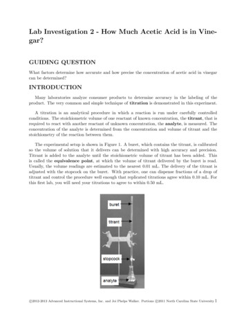
Section 1 IntroductionInstallation and Operation ManualX-TMF-5850E-MFC-engPart Number: 541B102AAGSeptember, 2009Brooks Model 5850E1-1 PurposeThe Brooks Model 5850E Flow Controller is a mass flow measurementdevice designed for accurately measuring and rapidly controlling flows ofgases. This instruction manual is intended to provide the user with all theinformation necessary to install, operate and maintain the Brooks 5850EMass Flow Controller. This manual is organized into five sections:Section 1Section 2Section 3Section 4Section 5Back CoverIntroductionInstallationOperationMaintenance & TroubleshootingReplacement PartsWarranty, Local Sales/Service Contact InformationIt is recommended that this manual be read in its entirety before attemptingto operate or repair the Model 5850E.1-2 DescriptionThe Brooks Model 5850E Mass Flow Controller is used widely in theSemiconductor Industry as well as many others, where manual, electronicor computer controlled gas handling occurs. The Model 5850E consists ofthree basic units: a flow sensor, a control valve and an integral electroniccontrol system. This combination produces a stable gas flow, whicheliminates the need to continuously monitor and readjust gas pressures.Standard features include:Fast Response Control permits rapid gas settling times with little or noover/undershoot. (Refer to Figure 1-1.)Soft Start provides a flow ramping function which slows down theintroduction of the process gas for those processes which cannottolerate rapid flow transition. (Refer to Section 2-6 and Figure 1-2.)Valve Override permits the user to fully open and close the control valveindependent of the command setting. (Refer to Section 2-8.)Setpoint (Command) permits the user to program the mass flow controllerwith an external 0-5 Vdc command potentiometer.(Refer to Section 2-7.)Low Command Valve Inhibit (Auto Shut-off) prevents the valve fromopening whenever the set-point is less than 2% of full scale.Removable Cleanable Sensor permits the user to clean or replace thesensor. (Refer to Section 4-4.)Output Limiting prevents possible damage to delicate data acquisitiondevices by limiting the output to 6.8 Vdc and -0.7 Vdc.1-1
Section 1 IntroductionBrooks Model 5850EFigure 1-1 Command Steps, Soft Start DisabledFigure 1-2 0 - 100% Command Step, Soft Start Enabled.1-2Installation and Operation ManualX-TMF-5850E-MFC-engPart Number: 541B102AAGSeptember, 2009
Section 1 IntroductionInstallation and Operation ManualX-TMF-5850E-MFC-engPart Number: 541B102AAGSeptember, 2009Brooks Model 5850EValve Off accessed via terminal J on the Card Edge or Pin 4 on the DConnector version. This feature allows the user to close the controlvalve independently of the command signal by supplying a TTL levellow signal to the proper terminal. This function is useful whenperforming repetitive flow operations or as a safety shutdown.(Refer to Section 2-11.)Valve Test Point/Purge accessed via terminal D on the Card Edge or Pin7 on the D-Connector version. This feature allows the user to monitorthe control valve voltage during operation. Shorting the valve test pointpin to power supply common will cause the valve to open regardless ofcommand input voltage. (Refer to Section 2-10.)Remote Transducer Input accessed via Terminal 5 on the Card Edge orPin 15 on the D-connector version. This feature allows the use of theintegral control electronics and valve to regulate flow in response to thesignal from an external 0-5 Vdc signal. The mass flow signal from theModel 5850E is still available for process monitoring.(Refer to Section 2-9.)1-3 SpecificationsStandard Ranges:3 sccm to 30 slpm* (Nitrogen equivalent)*Standard temperature and pressure in accordance with SEMI(Semiconductor Equipment and Materials International) standard: 0 Cand 101.3 kPa (760 Torr).Accuracy: 1% full scale including linearity at calibration conditions. 1.5% full scale including linearity for flow ranges greater than 20 slpm.Repeatability:0.25% of rateResponse Time:Less than 3 seconds response to within 2% of full scale final value with a 0to 100% command step.Power Requirements (NC Valve): 15 Vdc 5%, 35 mA-15 Vdc 5%, 180 mA3.5 watts power consumption1-3
Section 1 IntroductionInstallation and Operation ManualX-TMF-5850E-MFC-engPart Number: 541B102AAGSeptember, 2009Brooks Model 5850EPower Requirements (NO Valve): 15 Vdc 5%, 215 mA-15 Vdc 5%, 180 mA11.85 watts power consumptionAmbient Temperature Limits:Operating: 40 F to 150 F (5 C to 65 C)Non-operating: -13 F to 212 F (-25 C to 100 C)Working Pressure:1500 psi (10.342 mPa) maximumDifferential Pressure:5 to 50 psi (minimum pressure drop depends on gas and range). Refer toOrifice Sizing, Section 4-6.Output Signal:0-5 Vdc into 2000 ohms or greater. Maximum ripple 3 mV.5 Volt Reference Output:5 Volts 0.2%. Maximum load 1 k ohms.Temperature Sensitivity:Zero: less than 0.075% F.S. per degree C.Span: less than 1.0% F.S. shift over 10-50 C rangePower Supply Sensitivity: 0.09% full scale per % power supply voltage variationMounting Attitude Sensitivity: 0.5% maximum full scale deviation after re-zeroingCommand Input:0-5 Vdc. Input resistance 200 k ohmLeak Integrity:1 x 10⁻⁹ Atm. cc/sec HeliumControl Range:50 to 1Mechanical Connection:Compatible with most popular mass flow controllers. Refer to Figure 2-1.Electrical Connection:Card edge, 20 terminals, gold over low stress nickel plated copper. 15-pinD-Connector (DA-15P)1-4
Installation and Operation ManualX-TMF-5850E-MFC-engPart Number: 541B102AAGSeptember, 2009Section 2 InstallationBrooks Model 5850E2-1 Receipt of EquipmentWhen the equipment is received, the outside packing case should bechecked for damage incurred during shipment. If the packing case isdamaged, the local carrier should immediately be notified regarding hisliability. A report should be submitted to the Product Service Department,Brooks Instrument, 407 West Vine Street, Hatfield, Pennsylvania 19440.Brooks Instrument407 W. Vine StreetP.O. Box 903Hatfield, PA 19440 USAToll Free (888) 554 FLOW (3569)Tel (215) 362 3700Fax (215) 362 3745E-mail: comBrooks InstrumentNeonstraat 36718 WX Ede, NetherlandsP.O. Box 4286710 BK Ede, NetherlandsTel 31 (0) 318 549 300Fax 31 (0) 318 549 309E-mail: BrooksEu@BrooksInstrument.comBrooks Instrument1-4-4 Kitasuna Koto-KuTokyo, 136-0073 JapanTel 81 (0) 3 5633 7100Fax 81 (0) 3 5633 7101Email: BrooksAs@BrooksInstrument.comRemove the envelope containing the packing list. Outside of your cleanarea, carefully remove the equipment from the packing case. Make surespare parts are not discarded with the packing material. Inspect fordamaged or missing parts.2-2 Recommended Storage PracticeIf intermediate or long-term storage is required for equipment, as suppliedby Brooks Instrument, it is recommended that said equipment be stored inaccordance with the following:a. Within the original shipping container.b. Store in a sheltered area, with the following conditions.1. Ambient temperature 21 C (70 F) nominal, 32 C (90 F) maximumand 7 C (45 F) minimum.2. Relative humidity 45% nominal, 60% maximum and 25% minimum.Upon removal from storage, a visual inspection should be conductedto verify the condition of the equipment is "as received". If theequipment has been in storage for an excess of ten (10) months orin conditions in excess of those recommended, all pressure boundary seals should be replaced and the device subjected to a pneumatic pressure test in accordance with applicable vessel codes.2-1
Installation and Operation ManualX-TMF-5850E-MFC-engPart Number: 541B102AAGSeptember, 2009Section 2 InstallationBrooks Model 5850E2-3 Return ShipmentPrior to returning any Brooks equipment to the factory, contact the factory for a Return Materials Authorization Number (RMA#). This can be obtainedat Brooks Instrument, Product Service Department, 407 West Vine Street,Hatfield, PA 19440-0903, or call toll free 1-888-554-FLOW (3569).Brooks Instrument407 W. Vine StreetP.O. Box 903Hatfield, PA 19440 USAToll Free (888) 554 FLOW (3569)Tel (215) 362 3700Fax (215) 362 3745E-mail: comBrooks InstrumentNeonstraat 36718 WX Ede, NetherlandsP.O. Box 4286710 BK Ede, NetherlandsTel 31 (0) 318 549 300Fax 31 (0) 318 549 309E-mail: BrooksEu@BrooksInstrument.comBrooks Instrument1-4-4 Kitasuna Koto-KuTokyo, 136-0073 JapanTel 81 (0) 3 5633 7100Fax 81 (0) 3 5633 7101Email: BrooksAs@BrooksInstrument.comAlso, completion of Form RPR003-1, Brooks Instrument DecontaminationStatement, as well as, a Material Safety Data Sheet (MSDS) for the fluid(s)used in the meter, is required before any Brooks Personnel can beginprocessing the equipment. Copies of the form can be obtained at one ofthe locations above.2-4 Gas ConnectionsStandard inlet and outlet connections supplied on the Model 5850E are1/4" compression fittings for flow rates up to 10 slpm, and 3/8"compression fittings for higher flow rates.Optional VCOTM and VCRTM connections are available upon request. Priorto installation, make certain all piping is clean and free of obstructions.Install the piping in such a manner that permits easy removal if theinstrument is to be removed for cleaning or test bench troubleshooting.2-5 Installation (Refer to Figs. 2-1 through 2-4)2-2
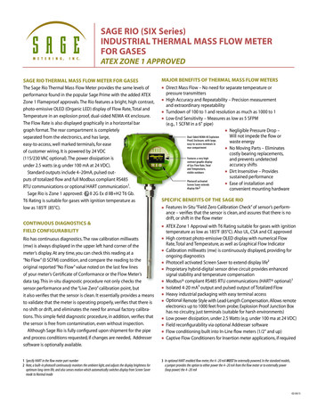
Installation and Operation ManualX-TMF-5850E-MFC-engPart Number: 541B102AAGSeptember, 2009Section 2 InstallationBrooks Model 5850EFigure 2-1 Model 5850E DimensionsRecommended installation procedures:a. The Model 5850E should be located in a clean, dry atmosphere relatively free from shock and vibration.b. Leave sufficient room for access to the electrical components.c. Install in such a manner that permits easy removal if the instrumentrequires cleaning.d. The Model 5850E Mass Flow Controller can be installed in any position.However, mounting in orientations other than the original factorycalibration (see data sheet) will result in a 0.5% maximum full scaleshift after re-zeroing.2-3
Installation and Operation ManualX-TMF-5850E-MFC-engPart Number: 541B102AAGSeptember, 2009Section 2 InstallationBrooks Model assisGroundChassisGround1 upplyCommon0-5 VoltSignalCommon0-5 VoltSignalCommon0-5 VoltSignalCommon2 BCommandCommonCommandCommonSignal &CommandCommonCommandCommon0-5 VoltSignalOutput0-5 VoltSignalOutput0-5 VoltSignalOutput0-5 VoltSignalOutput3 n 15 VdcSupply 15 VdcSupply 15 VdcSupply 15 VdcSupplyValve TestPoint/PurgeValve TestPointNot UsedValve TestPoint/PurgeNot UsedNot UsedNot UsedRemoteTransducerInput***5 ENot UsedValveNot UsedPointTestNot UsedNot UsedZenerTestZenerTestNot Used6- 15 VdcSupply- 15 VdcSupply- 15 VdcSupply- 15 VdcSupplySlotSlotSlotSlot7 H*SlotSlotSlotSlot (G)Not UsedNot UsedNot UsedNot Used8 J*Not UsedNot UsedNot UsedNot Used (H)Not UsedNot UsedNot UsedValve Override9 K*Not UsedNot UsedOpen/CloseValveNot Used (I)CommonNot UsedNot Used 5V Ref. *** orValve Returnor Not Used10 L*ValveOffNot UsedOffNot UsedValve Off (J)4 DF* Unit designates Pins H, J, K, & L as G, H, I, & J** Jumper Selectable*** Factory Activated Option2-4Figure 2-2 Model 5850E Card Edge Connector Comparison Guide
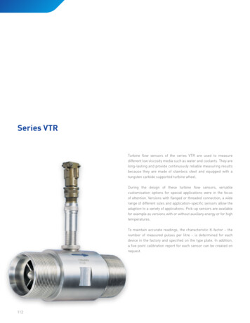
Installation and Operation ManualX-TMF-5850E-MFC-engPart Number: 541B102AAGSeptember, 2009Section 2 InstallationBrooks Model 5850EFigure 2-3 Model 5850E Card Edge Connector Hookup DiagramPIN NO.123456789101112131415FUNCTIONCommand Common (Potentiometer Pin "CCW")0-5 Volt Signal OutputNot UsedValve Off 15 Vdc Supply-15 Vdc SupplyValve Test PointCommand Input (Potentiometer Pin "S")Supply Voltage Common0-5 Volt Signal Common 5 Volt Reference Output (Potentiometer Pin "CW")Valve OverrideNot UsedChassis GroundRemote Transducer Input*COLOR :1. Cable shield tied to chassis groundin meter connector. Make noconnection on customer end.2. All power leads must be connectedto power supply.*Jumper SelectableFigure 2-4. D-Connector Pin Arrangement2-5
Installation and Operation ManualX-TMF-5850E-MFC-engPart Number: 541B102AAGSeptember, 2009Section 2 InstallationBrooks Model 5850Ee. When installing controllers with full scale flow rates of 10 slpm orgreater, be aware that sharp, abrupt angles in the system piping directlyupstream of the controller may cause a small shift in accuracy. Ifpossible, have at least ten pipe diameters of straight tubing upstream ofthe Model 5850E Mass Flow Controller.Note: The control valve in the Model 5850E provides precision controland is not designed for positive shut-off. If positive shut-off is required,it is recommended that a separate shut-off valve be installed in-line.2-6 In-Line FilterIt is recommended that an in-line filter be installed upstream from thecontroller to prevent the possibility of any foreign material entering the flowsensor or control valve. The filtering element should be replacedperiodically or ultrasonically cleaned.Table 2-1 Recommended Filter Size.Maximum Flow Rate100 sccm500 sccm1 to 5 slpm10 to 30 slpmRecommended Filter Size1 micron2 micron7 micron15 micronNote: The above lists the maximum recommended porosity for each flowrange. It is recommended that the minimum micron porosity that does notlimit the full scale flowrate be used.Electrical InterfacingTo insure proper operation, the Model 5850E must be connected perFigures 2-3 and 2-4, and configured according to Sections 2-6 to 2-13.2-6As a minimum the following connections must be made for newinstallations:Chassis Ground0-5 Volt Signal Common0-5 Volt Signal Output 15 Vdc Supply-15 Vdc SupplyCommand InputCommand CommonSupply Voltage CommonValve Return (Refer to Section 2-12 for jumper configuration)
Installation and Operation ManualX-TMF-5850E-MFC-engPart Number: 541B102AAGSeptember, 2009Section 2 InstallationBrooks Model 5850EFor installations which replace Unit Instruments UFC-1000's, (Card Edgeversion) Pin 10 is frequently grounded. In these situations the 5 Voltreference output must be disabled. Refer to Section 2-12.For installations which will be connected to Brooks secondary electronics,the Card Edge version must have the 5 Volt reference enabled on Pin 10and the D-Connector version should be configured for external valvereturn. Refer to Section 2-12. If the Model 5850E was shipped as asystem with Brooks secondary electronics then the electronics will alreadybe configured properly.Note: To obtain access to the jumpers for the following options theelectronics cover can must be removed. Remove the can by removing thethree screws and the valve connector. The can must be replaced beforereturning the unit to service.2-7 Soft StartRefer to Figures 3-3 and 3-4. To enable soft start, place the red jumper onthe controller printed circuit board at J2 in the (ss) position.To disable soft start, place the red jumper on the controller printed circuitboard at J2 in the (n) position.2-8 Remote Setpoint (Command) InputIf the mass flow controller is to be commanded by an external 0-5 Vdcsignal, the command potentiometer is not used.The command input hookup is as follows:a. Card Edge ConnectorConnect the external command voltage to Terminal A and externalcommand return to Terminal B. Refer to Figures 2-2 and 2-3.b. D-ConnectorConnect the external command voltage to Terminal 8 and externalcommand return to Terminal 1. Refer to Figure 2-4.2-9 Valve OverrideThe valve override function allows full opening and closing of the valveindependent of the command setting. The unique command reset featureprevents flow overshoot when the controller goes from valve overrideclosed to normal control. The valve override for the mass flow controller isas follows:a. To open the valve, apply 15 Vdc to the valve override terminal.b. To close the valve, apply -15 Vdc to the valve override terminal.2-7
Installation and Operation ManualX-TMF-5850E-MFC-engPart Number: 541B102AAGSeptember, 2009Section 2 InstallationBrooks Model 5850Ec. Isolating the valve override terminal returns the controller to normaloperation.1. Card EdgeThe valve override function can be accessed from Terminal 9. Referto Figure 2-3.Note: For normal operation, Terminal 9 must be left open (floating).2. D-ConnectorThe valve override function is accessed from Terminal 12. Refer toFigure 2-4.2-10 Remote Transducer InputRefer to Figures 3-3 and 3-4. To allow the Model 5850E control circuitryand valve to be used with a 0-5 Vdc external transducer signal, a greenjumper is moved to the lower two pins at J7. With this feature enabled, a 05 Vdc signal may be applied to the external transducer input terminal. TheModel 5850E controller circuitry will modulate the valve position to increaseor decrease the flow rate to maintain the transducer output at the desiredset-point. The control circuitry is reverse acting, e.g., for an increase intransducer output, the flow will correspondingly be decreased.2-11 Valve Test Point/PurgeRefer to Figures 2-2, 2-3 and 2-4. The valve voltage can be monitored onPin D of the Card Edge version and Pin 7 of the D-Connector version. Thisvoltage relative to circuit common is proportional to the valve voltage perthe following equation:Valve Voltage (1.53 x TP3) 20.7( Note: The valve voltage calculation is an approximate value.)Shorting the valve test point pin to power supply common will cause thevalve to open regardless of command input voltage.2-12 Valve OffRefer to Figures 2-2, 2-3 and 2-4. The control valve can be forced closedregardless of command input signal by applying a TTL level low ( .4 Vdc)to Terminal L of the Card Edge version or Pin 4 of the D-Connectorversion. A TTL level high or floating at this pin has no effect.2-8
Installation and Operation ManualX-TMF-5850E-MFC-engPart Number: 541B102AAGSeptember, 2009Section 2 InstallationBrooks Model 5850E2-13 Five-Volt Reference Output/Valve Drive Configurationa. Card EdgeRefer to Figures 2-3 and 3-3. Terminal 10 can be jumper selected as 5 Voltreference output, external valve return or “not used.” The 5 Volt referenceoutput is required if a potentiometer is to be used to generate thecommand signal. To enable the 5 Volt reference output on Terminal 10,place the yellow jumper at J1 in the D-E position. To disable the 5 Voltreference output, place the yellow jumper at J1 in the E-F position.To minimize the effect of resistance in the connection wiring, a separate“external valve return” can be accessed on Pin 10. To enable this feature,place the black jumper at J1 in the B-D position and connect Terminal 10 topower supply common. If the “external valve return” is not enabled, placethe black jumper at J1 in the B-C position.Note: If the “external valve return” feature is not enabled, the valve voltageis returned internally on the printed circuit board and the connection wiringresistance must be less than 0.2 ohms.b. D-ConnectorRefer to Figures 2-4 and 3-4. The 5 Volt reference is always available onPin 11.To minimize the effect of resistance in the connection wiring, a separate“external valve return” can be accessed on Pin 3. To enable this feature,place the black jumper at J1 in the B-D position and connect Pin 3 topower supply common. If the “external valve return” is not en
X-TMF-5850E-MFC-eng Part Number: 541B102AAG September, 2009 Brooks Model 5850E Dear Customer, We appreciate this opportunity to service your flow measurement and control requirements with a Brooks Instrument device. Every day, flow customers all over the world turn to Brooks Instrument for solutions to their gas and liquid low-flow applications.