Transcription
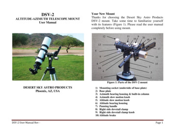
DSV-2ALTITUDE-AZIMUTH TELESCOPE MOUNTUser ManualYour New MountThanks for choosing the Desert Sky Astro ProductsDSV-2 mount. Take some time to familiarize yourselfwith its features (Figure 1). Please read the user manualcompletely before using mount.1211109201819131756168157144321Figure 1: Parts of the DSV-2 mountDESERT SKY ASTRO PRODUCTSPhoenix, AZ, USADSV-2 User Manual Rev -1) Mounting socket (underside of base plate)2) Base plate3) Azimuth bearing housing & built-in column4) Azimuth slow motion knob5) Altitude slow motion knob6) Altitude bearing housing7) Panning handle8) Right side dovetail clamp9) Right side dovetail clamp knob10) Altitude brakePage 1
11) Bubble level12) Left side dovetail clamp knob13) Left side dovetail clamp14) Left side dovetail clamp set screws (3)15) QBS adjustment plate16) QBS balancing weight17) QBS balancing track18) QBS adjustment plate slots (2)19) QBS adjustment knobs (2)20) QBS short dovetail adapterPackage contentsThe shipping box contains a fully assembled DSV-2mount, a fully assembled Quick Balance System (QBS)unit, Velcro dot balance point markers, a Velcro strip andwrenches. Other items may be present in the boxdepending on your specific order. Please removeprotective wrapping prior to use.mount, telescopes and accessories used and equippedwith mounting bolt that matches the mount.Leveling the MountUse the built-in bubble level to level the mount. Whileperfect leveling is not required, an out of level mount willnot perform well.Attaching the QBSThe QBS attaches to the left or right side dovetail clampby sliding the short dovetail adapter into thecorresponding dovetail clamp, as shown in Figure 2. Tofacilitate installation, place the balancing weight so that itis aligned with the altitude axis. Tighten dovetail knob tosecure QBS in place.Recommended PayloadThe DSV-2 mount is recommended for use withRefractor telescopes up to 102mm f/7, SchmidtCassegrain telescope (SCT) up to 8” aperture andMaksutov-Cassegrain telescope (MCT) up to 6” aperture.Attaching mount to a tripodThe mount attaches to a tripod (sold separately) bythreading the tripod’s mounting screw onto the mountmounting socket. Recommended tripods are Desert SkyAstro Products Surveyor-Style Tripod or any heavy dutytripod capable of supporting the combined weight of theDSV-2 User Manual Rev -Figure 2: Attaching the QBSPage 2
The QBS is shipped configured for mounting to the rightside dovetail clamp. If left side installation is desired,reverse the balancing track so the QBS is configured asshown in Figure 3.Figure 3: QBS in left side clamp configurationAttaching a telescope and setting up QBSQBS must be setup prior to operating the mount. Properbalancing of the altitude axis is essential for the correctoperation of the DSV-2 mount.Prepare the telescope to be used with the mount byinstalling the star diagonal, finder, tube rings and thelightest eyepiece you will regularly use. The telescopemust be equipped with a Vixen-style dovetail bar adapterin order to be attached to the DSV-2 mount. Prepare theQBS by applying the supplied Velcro strip to the topedge of the balancing track.DSV-2 User Manual Rev -1. Adjust the QBS so that the balancing track is allthe way up on the rear adjustment slot andapproximately in the middle of the frontadjustment slot, and the balancing weight is all theway to the back end of the track. The balancingtrack is adjusted by loosening the two knurledQBS knobs and sliding the track on the adjustmentslots, then tightening the adjustment knobs. Thebalancing weight is adjusted by turning itcounterclockwise to loosen, sliding it to the desiredposition and turn weight clockwise to set in place.Insert the telescope and slide the telescope back orforth on the dovetail clamp (or the telescope on thetube rings) to balance the telescope in thefront/back direction as shown in Figure 4. Tightendovetail clamp knob once telescope is balanced.Small EPVelcro stripSlide telescope back or forth to balance,tighten dovetail clamp knob after balancing.Balancing weight all the way back and balancingtrack all the way up on adjustment slot.Figure 4: QBS setup step 1Page 3
2. Point telescope at or near the zenith and check iftelescope is balanced for high pointing angles(telescope should not tip forward or back). Adjustthe position of the balancing track on the rearadjustment slot as needed to obtain balance. Thismay be necessary if your smallest EP is not sosmall and/or you are using a finder scope. SeeFigure 5.Small EPnot tend to drift in any direction. Mark the rear end of thebalancing track with one of the supplied Velcro dots3. Engage the altitude brake. Remove the small EPand insert the largest EP you intend to regularlyuse with your telescope and the DSV-2 mount.Typically, up to a 35mm Super Wide Angle or26mm Ultra Wide Angle can be balanced with a102mm f/7 refractor (41mm SWA/31mm UWAwith an 80mm F/7 refractor), although this willdepend on the particular telescope being used. Forextra heavy EPs or binoviewers an extra weightmay be required. Call or email for more details.Release the altitude brake while holding thetelescope to prevent sudden tipping. Slide thebalancing weight forward on the track until thetelescope is balanced in the back/front direction, asshown in Figure 6.Large EPSlide rear end of balancing track onthe rear adjustment slot to balancescope at high pointing anglesFigure 5: QBS setup step 2.When the telescope is properly balanced, it takes thesame amount of force to swing it up or down and it willSlide balancing weight forward untilscope is balanced in the front/backdirection.Figure 6: QBS setup step 3DSV-2 User Manual Rev -Page 4
Mark the balancing point with one of the supplied Velcrodots.4. Point telescope at or near the zenith and check iftelescope is balanced for high pointing angles(telescope should not tip forward or back). Adjustthe position of the balancing track on the frontadjustment slot as needed to obtain balance, asshown in Figure 7.not tend to drift in any direction. Tighten the QBSadjusting knobs to set the balancing track in place.Once the balancing points for the smallest and largestEPs in your set have been identified, the balancing pointsfor the remaining EPs can be found by installing the EPand adjusting the balancing weight on the track until thetelescope is balanced. Mark each balancing point withone of the Velcro dots supplied (5 total).Changing EyepiecesTo change EPs during an observing session, engage thealtitude brake, remove the current EP, the install the newEP and move the balancing weight to the balancing pointcorresponding to the new EP. Then release the altitudebrake to continue observing.Large EPSlide balancing track on the frontadjustment slot to balance scope athigh pointing anglesFigure 7: QBS setup step 4When the telescope is properly balanced, it takes thesame amount of force to swing it up or down and it willDSV-2 User Manual Rev -Removing the telescopeIf you remove the telescope for storage at the end of theobserving session, put an indexing mark (small piece oftape or crayon mark) on the telescope’s dovetail bar torecord its position with respect to the dovetail clamp.This way you will not need to setup the QBS again whenthe telescope is reinstalled on the mount.Removing the QBSThe QBS can be removed for mount transportation orstorage. Put an indexing mark (small piece of tape orcrayon mark) on the QBS dovetail adapter to record itsposition with respect to the dovetail clamp. This way youPage 5
will not need to setup the QBS again when it isreinstalled on the mount.Slow Motion ControlsThe DSV-2 is equipped with geared slow motioncontrols. Slip clutches allow the slow motion controls tomove the mount without the need to unlock/lock the axesfor slewing. A small amount of friction is used to transferthe slow motion control inputs to the mount (hence theimportance of properly balancing the mount).Turning the altitude slow motion knob clockwise willmove the telescope towards the zenith andcounterclockwise will move the telescope move thetelescope towards the horizon.the DSV-2 mount makes it ideal for scanning the skywith a short focal length telescope. The handle can beremoved by unthreading it from the dovetail clamp.Double Telescope OperationThe DSV-1 can be used with two telescopes in a side byside configuration. To use in double telescope mode, atleast one of the scopes must be equipped with tube rings.In this mode, the QBS (with the short dovetail adapterremoved) in attached to the top holes of the tube rings ofone of the scopes, as shown in Figure 8.It is preferable to attach the QBS to the lighter of the twotelescopes being used, for better Azimuth axis balance.Follow the steps listed in the “setting up QBS” section tosetup QBS for double telescope use.Turning the azimuth slow motion clockwise will movethe telescope to the right (clockwise as seen from the top)and counterclockwise moves the telescope to the left.The slow motion controls are adjusted at the time themount is assembled. No adjustments are needed duringnormal use. If you believe the slow motion controls inyour mount need adjustment, please email for furtherinstructions.Panning HandleA panning handle is provided standard with the DSV-2mount. It can be used for slewing the mount and pointingthe telescope. The panning handle and lock-less design ofDSV-2 User Manual Rev -Figure 8: Setup for double telescope operationPage 6
Aligning the two dovetail clampsFor double telescope operation, you may want to alignthe two dovetail clamps so the two scopes point at thesame object. Because the alignment between the opticaltube and dovetail bar varies from telescope to telescope,alignment of the dovetail clamps must be made with theactual telescopes to be used. Alignment is more easilydone during the day. Find a distant, easily visible object(i.e. a power transmission tower).WARNING:NEVER POINT TELESCOPES AT OR NEAR THE SUN.DAMAGE TO THE EYES AND/OR THE INSTRUMENTMAY OCCUR.Perform the following steps:1. Remove the QBS if it is attached to the mount.2. Mount a telescope (with star diagonal, EPs, etcattached) on the dovetail clamp on which youintend to use the telescope (for example, if youintend to use a refractor on the left side and aMaksutov on the right side, they should bemounted to that side during alignment).3. Roughly balance the scopes by sliding back orforth on the dovetail clamps as needed, tighten thedovetail clamp knobs.4. Point the mount to the object chosen and center itin the field of view of the right side telescope.5. Engage the altitude brake tightly.6. Loosen slightly the left side dovetail clampsetscrew (located on the underside of the clamp).DSV-2 User Manual Rev -7. Rotate up or down the left side telescope on thealtitude axis as needed so the object is centered inup/down direction in the field of view of the lefthand telescope (object may not be centered in theleft/right direction, this will be corrected in thefollowing steps).8. Tighten the left side dovetail clamp setscrew.9. Release the altitude brake.10.Center (up/down and left/right) the alignmentobject in the field of view of the left side telescope.Object should be centered in the up/down directionin the field of view of the right side telescope. Ifnot, repeat steps 4-8.11. Engage the altitude brake.12. On the right side dovetail clamp, loosen the frontsetscrew (located next to the panning handle) andback setscrew (located opposite the panninghandle).13. Tighten the front or back dovetail clamp setscrewas needed to center the object in the left/rightdirection of the right side telescope. Whichsetscrew to tighten will depend on the type oftelescope and type of diagonal (star or correctimage) used.14. Once the object is centered in both directions inthe field of view of both scopes, tighten thesetscrews.15. Reinstall QBS as needed for single telescope ordouble telescope operation.Page 7
Alignment Notes:a. If you notice after aligning the dovetail clamps thatthe friction in the altitude axis has increased ordecreased compared to the original setting, it canbe adjusted by tightening or loosening either sidedovetail clamp cap screw (located on the center ofthe face of the dovetail clamp, scopes must beremoved to perform this adjustment). Only a smalladjustment is needed, work in small incrementsuntil the original setting is restored. The amount offriction in the altitude axis must be equal to that inthe azimuth axis and just enough for the slowmotion controls to operate. If in doubt, email us forfurther instructions.b. The right side dovetail setscrews offer a limitedadjustment range. Prior to attempting to align thedovetail clamps, make sure the dovetail bar isaligned with the optical tube. If the misalignmentbetween the dovetail bar and optical tube is toolarge, alignment of the views may not be possible.Mount CareStore mount protected from the elements. If the mountbecomes wet or soiled during use, wipe water or dirt withclean lint-free cloth and allow it to dry indoors. Allbearings and moving parts have been lubricated atmanufacture and do not require further lubrication duringuse.The mount is not intended to be disassembled or servicedby user. Please call or email if mount needs service.Warranty and ServiceYour mount is guaranteed to be free of material andworkmanship defects for one year from date of originalpurchase. Within this period of time, Desert Sky AstroProducts will repair or replace at its discretion anydefective components. This is the only and exclusivewarranty offered. Abuse, accidental damage andunauthorized modifications & repairs are not covered bythe warranty.To obtain service, please call 602-550-4331 or emaildesertskyastro@cox.net to make return arrangements. 2011 Desert Sky Astro Products.c. The alignment of the dovetail clamps is specificfor the scopes used during the alignment process.If you later switch to different scopes, the viewsmay not be aligned (due to differences in thealignment between the telescope’s optical tube anddovetail bar). Repeat alignment process for thenew telescopes, if desired.DSV-2 User Manual Rev -Page 8
DESERT SKY ASTRO PRODUCTS Phoenix, AZ, USA Your New Mount Thanks for choosing the Desert Sky Astro Products DSV-2 mount. Take some time to familiarize yourself with its features (Figure 1). Please read the user manual completely before using mount. Figure 1: Parts of the DSV-2 mount 1) Mounting socket (underside of base plate)