Transcription
Rainbow PowerVictron DIY SolarInstallation Manual[Type here]
IndexIntroductionSafetyScope of DeliveryAdditional Tools RequiredProduct DescriptionInstallation RequirementsDistribution BoardSolar PanelsArray WiringBatteriesElectrical ConnectionsConnection of Optional AccessoriesInverterBattery Charger / GeneratorCommissioningAdditional InformationTechnical DataContact[Type here]
IntroductionThe Rainbow Power Victron DIY Solar Systems are compact, do-it-yourselfpower systems. These systems can energize a lot of small gear, including anefficient fridge. Suitable for low-consumption or infrequent electricity users. Idealfor remote sheds, beach huts, motor homes or weekenders.A Victron DIY Off-Grid System consists of a prewired wall-mountable distributionboard complete with MPPT solar regulator, Circuit breaker referred to as CB.The system can be used on 12 or 24 volt battery banks up to 1000 AH, and canintegrate a maximum of 4 x 260 watt solar panels (@ 12v) or 6 x 260 watt solarpanels (@24v).The board offers easy integration of a Victron Battery Voltage Monitor (BMV),battery charger and a DC/AC battery inverter (300w @ 12v, 700W @ 24V).The distribution Board comes Prewired with a 10 amp cigarette lighter socket, 2x USB ports 2.1 mm DC socket for lights and 40 amp Anderson Plug for Inverter.SafetyThe RPC Victron MPPT Distribution board is an electrical device with potentiallydangerous equipment. Care is required to protect yourself from injury. Read thissection carefully and follow all safety precautions at all times. Please Take noteof !Warning! throughout this guide.Please refer to your specified wiring diagram to ensure correct connectionof all equipment.Please NoteRainbow Power Co. takes no responsibility for any faults that occur due toincorrect connection or use of this equipment.If after reading this manual you have any questions relating to the installation oroperation of your system please contact RPC on 02 6689 1430[Type here]
Danger to life due to Spark HazardOperating damaged equipment can lead to hazardous situations that result in death orserious injuries due to spark hazards and resulting risk of fire. Only use equipment when it is technically faultless and in an operationally safe state. Check the equipment for visible damage. Make sure that all external safety equipment is freely accessible at all times. Make sure that all safety equipment is in good working order.Danger to life due to explosive gasesExplosive gases may escape from the battery and cause an explosion if ignited. Thiscan result in death or serious injury. Protect the battery environment from open flames, embers or sparks. Install, operateand maintain the battery according to the manufacturer's specifications. Do not heat the battery above the temperature permitted. Ensure that the battery room or enclosure is sufficiently ventilated.Chemical burns and poisoning due to battery electrolyteIf handled inappropriately, electrolyte from the battery can burn the eyes, respiratorysystem and skin, and emit toxic fumes. This may result in blindness and seriouschemical burns. Protect the battery enclosure against destruction. Do not open or deform thebattery. Whenever working on the battery, wear suitable personal protective equipment suchas rubber gloves, apron, rubber boots and goggles. Rinse acid splashes thoroughly with clear water for a long time and consult a doctor. Install, operate, maintain and dispose of the battery according to the manufacturer'sspecifications. Spills can be neutralized with a mixture of Bi-Carbonated Soda and waterRisk of injury due to short-circuit currentsShort-circuit currents in the battery can cause heat build-up and electric arcs. Burns oreye injury due to flashes may result. Remove watches, rings and other metal objects. Use insulated tools. Do not place tools or metal parts on the battery.Working at heightsClimbing up the roof exposes you to the risk of falling off. A physical barrier(scaffolding) or a correctly supported safety harness is required whenever anyoneclimbs onto the roof.Lifting InjuriesThe batteries are heavy and should be moved using good lifting techniques. Keep back straight, Stomach muscles should be tightened and lifting should be done with your legs.[Type here]
If they are too heavy to lift by one person then two people or mechanical lifting aidswill be required[Type here]
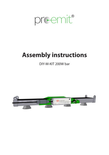
Scope of DeliveryYour kit includes the following itemsRPC Distribution BoardBattery BoxSolar PanelsBattery LeadsAdditional Tools RequiredScrew DriverShifterWire Cutters20mm hole sawMultimeter[Type here]BatteriesSolar Cable
Product DescriptionRainbow Power Victron DIY Solar consistsThe Rainbow Power MPPT Mini Distribution board comes with: Victron MPPT solar controller 9 pole DC Distribution box 1 x 63A DC CB Main battery - double pole 1 x 20A DC CB solar controller – double pole 1 x 13A CB for Cigarette socket/USB socket 1 x 40A CB for Pluggable Inverter. 1 x 6A CB for 2.1mm DC Socket for Sundaya Ulita Lighting 1 x inline fuse for digital LED Voltmeter 1 x 40A CB for Battery charger Optional[Type here]
Victron MPPT Solar RegulatorThe BlueSolar -MPPT charge controller is able to charge a lower nominalvoltage battery from a higher nominal voltage PV array, and is rated at max 100Vopen circuit voltage (on input).Volt MeterThe Led Voltmeter provides information regarding your battery voltage. This isuseful in the operation of your system. Please refer to your Operation Manual forfurther details.Battery Monitor (BMV) OptionalHigh precision battery monitor from Victron Energy with the basic displayoptions, such as voltage, current and ampere-hours consumed, the BMV-700series also displays state of charge, time to go, and power consumption in watts.InverterVictron Energy Phoenix Inverter 12V 300W or 24v 700W, with 230 volt AC output(standard AU/NZ outlet).The Phoenix is built for professional duty and yet competitively priced withoutcompromise in performance. The compact Phoenix delivers a pure sinusoidal(sine wave) output waveform and an impressive start up power (peak power).Please refer to the Victron Phoenix SeriesOptional Battery ChargerCompact battery charger in a wall-mountable, compact IP22 enclosure.The Blue Power charger features a microprocessor controlled 'adaptive' batterymanagement. The adaptive feature will automatically optimize the chargingprocess relative to the way the battery is being used.Note!Please refer to supplied manufacturer’s equipment manuals for detailedinstructions on installation and operation of each piece of equipment.[Type here]
Installation RequirementsDistribution BoardThe Rainbow Power Victron MPPT Distribution Board will need to be placed in acool, dry place, with enough room to plug your optional inverter into theAnderson plugs on the Distribution board.Solar PanelsSolar Panels need to be secured in a sunny position close to the RPCDistribution board. The wire size needs to be large enough to overcome theresistance in the cable which causes voltage drop. If the cable length is 20m apair of 4 mm 2 cables can be used, if cable run is between 20-30m 6mm2 cableis advised. Panels should preferably face due north at an optimum sun angle ofbetween 20 – 40 degrees from horizontal depending on your latitude. This willget the most power from your panel. Please consult your framing installationmanual for detailed installation instructions.[Type here]
PV Array WiringTo increase safety, the PV array wiring in RPC renewable energy systemsoperates at less than 100 VDC. Although this increases safety, precautionsagainst faults and fire risks should be taken. All PV array wiring should beprotected from environmental damage. Protection from UV, Water and Verminneeds to also be considered. RPC recommends the use of conduit or otherprotective measures to alleviate these risks.PV Panels come in a range of voltages. Your installation may require acombination of series and/or parallel connections to achieve the correct solarvoltage for your system. Please consult with the PV data sheet and your “WiringDiagram” for correct configuration details. We have provided a generic diagramin this manual. Make sure that the PV Panels all have the same electricalcharacteristics, if they are not of the same brand when connecting to your ‘RPCMini Distribution board’.BatteriesThe Batteries need to be housed in a safe place out of the sun, which allowsadequate ventilation for any explosive gases to dissipate. The batteries ideallyshould be located in a lockable box with vermin proof ventilation holes. TheBattery Box needs to ensure escaping hydrogen gas will not be exposed tosparks, naked flames or electrical equipment. Battery boxes and appropriatebattery warning signs can be supplied by RPC if required.Placement of Battery ventilation in box to stop buildup of explosive gases.[Type here]
[Type here]
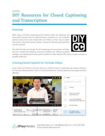
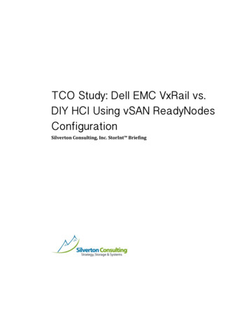
Electrical ConnectionsPhoto 1: Inside of box showing connection points for solar.GlandentryforsolarcableSolarDC CBPos & NegSolarconnectionpointConnecting Solar Panels.1 Make sure the MAIN BATTERY ISOLATOR is turned off and solar array cablesare disconnected from the panels via the MC4 plug and socket.2 Open DC distribution box and locate the double pole Solar DC CB located atthe far right hand side of the din rail.3 The PV array cables will feed into the distribution board through the gland atthe top of the box.4 Connect the Positive solar cable to the bottom positive terminal Solar ofthe Solar DC CB5 Connect the Negative - solar cable to the bottom negative terminal Solar - ofthe Solar DC CBOnly two strings per CB, as per you wiring diagram. Solar “Strings” are panelsconnected in series to give a specific voltage. The string voltage must neverexceed 100 OCV. Before turning on check with a Multimeter to make surepolarity is correct and voltage is 100VDC.[Type here]
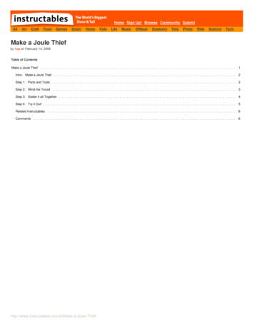
Battery ConfigurationBattery banks are made up of multiple 2v cells. Cells are assembled intoindividual batteries of 2, 6 or 12V. These units are combined in series to attainthe designed system voltage of (2 x 6v 12VDC , 4 x 6v 24 VDC)To make a Series connection the POS from one battery will be connected to the-NEG of the second battery and so on until the desired voltage is achieved byadding the individual battery voltages.Connecting 1 x 12V batteryConnect the POS lead from the distribution board onto the POS batteryterminal. Connect the -NEG lead from the distribution board onto the -NEG poleon the battery. Make sure all connections are tight.Connecting 2 x 6V batteriesIf your system is supplied with 2 x 6V batteries, you will need to connect them inseries. Make sure all connections are tight.[Type here]
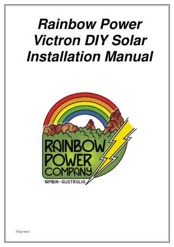
12v & 24v Battery Bank Configuration .2 x 6v 12v6 x 2v 12v[Type here]4 x 6v 24v12 x 2 v 24v
To Connect the Batteries,1. Drill a hole for the positive and negative battery cables through the sideof the battery box.2. Connect the Battery POS cable from you distribution board to thepositive terminal on your battery and the Battery -NEG cable to thenegative terminal on your battery.3. Connect battery (or batteries) interconnect cables, if applicable, in thecorrect configuration as shown in your “Wiring Diagram”. Check voltagewith a Multimeter to determine battery voltage and correct polarity.4. Make sure all connections are tight. Check that voltage and polarity arecorrect with a Multimeter at the ‘Main Battery Isolator’ terminals.5. Smear Petroleum jelly or a similar product onto the battery terminals, thiswill help protect the terminals from corrosion.!Warning!Make sure all Circuit Breakers are in the off position before working onBatteries.!Warning!When connecting the batteries be careful not to connect between positiveand negative on the same battery. Batteries can, under fault conditions,deliver thousands of amps and explode spraying sulphuric acid.!Warning!Lead Acid Batteries contain Sulphuric Acid. Care is required as well as useof appropriate Safety Equipment (Safety Glasses, Rubber gloves and aleather apron, insulated tools). If Batteries are Flooded Lead acid batteries(FLA), they require demineralized water to be added periodically. If anyacid has been spilt from the batteries a Bi-carb Soda and water mixtureshould be used to neutralize the acid. Do not get this in the battery.GEL or VRLA or Sealed lead acid batteries do not require anything addedto them but still require care when handling.[Type here]
Connecting Optional AccessoriesThe RPC MPPT Mini Distribution board also has the ability to connect a smallinverter via an Anderson plug. A battery charger can also be installed with theinclusion of an appropriate sized CB. Always be sure to check that wire and CBsare the right size for the appliance and application. See tables 2,3 & 4 for wiresize and allowable voltage drop.InverterThe inverter connects to the Rainbow Power Distribution board via a 50amp Anderson plug located at the bottom of the board( Pictured below). 230 VoltAC connection is via a standard 10 amp AU/NZ Plug. Before plugging orunplugging the inverter ensure you turn off the inverter and CB beforeconnecting into the Anderson plugs on the Rainbow Power DC Distribution box.[Type here]
Battery Charger / GeneratorThe optional Battery Charger can be hard wired via an additional CB on the dinrail. The right sized CB should be selected to protect the wiring between thebattery charger and the distribution box (please see wiring guide Tables 1-3)Adding Additional CB to your systemWhen adding additional CB to your system you will need to energize the top ofthe CB by adding a short linking wire the, same size as the Batterie Chargercable, between the top of the existing CB and the top of the additional CB.Connecting the Battery Charger1. Shut down your system via shutdown procedure.2. Connect Battery Charger NEG to Battery Negative link in DistributionBoard3. Connect Battery Charger POS to bottom
Array Wiring Batteries Electrical Connections Connection of Optional Accessories Inverter Battery Charger / Generator Commissioning Additional Information Technical Data Contact [Type here] Introduction The Rainbow Power Victron DIY Solar Systems are compact, do-it-yourself power systems. These systems can energize a lot of small gear, including an efficient fridge. Suitable for low .