Transcription
Backflow Prevention Productswatts.com
Table of ContentsGeneral Information . . . . . . . . . . . . . . . . . . . . . . . . . . . . . . . . . . . . . . . . . . . . . . . . . . . . . . . . . . . . . . . . . . . . . . . . . . . . . . . . .2Backflow Applications . . . . . . . . . . . . . . . . . . . . . . . . . . . . . . . . . . . . . . . . . . . . . . . . . . . . . . . . . . . . . . . . . . . . . . . . . . . . . .2Section 1 – Double Check Valve Assemblies757, 757N . . . . . . . . . . . . . . . . . . . . . . . . . . . . . . . . . . . . . . . . . . . . . . . . . . . . . . . . . . . . . . . . . . . . . . . . . . . . . . . . .4757Na . . . . . . . . . . . . . . . . . . . . . . . . . . . . . . . . . . . . . . . . . . . . . . . . . . . . . . . . . . . . . . . . . . . . . . . . . . . . . . . . . . . .6774 . . . . . . . . . . . . . . . . . . . . . . . . . . . . . . . . . . . . . . . . . . . . . . . . . . . . . . . . . . . . . . . . . . . . . . . . . . . . . . . . . . . . . .8709 . . . . . . . . . . . . . . . . . . . . . . . . . . . . . . . . . . . . . . . . . . . . . . . . . . . . . . . . . . . . . . . . . . . . . . . . . . . . . . . . . . . . .10007 . . . . . . . . . . . . . . . . . . . . . . . . . . . . . . . . . . . . . . . . . . . . . . . . . . . . . . . . . . . . . . . . . . . . . . . . . . . . . . . . . . . . .12719 . . . . . . . . . . . . . . . . . . . . . . . . . . . . . . . . . . . . . . . . . . . . . . . . . . . . . . . . . . . . . . . . . . . . . . . . . . . . . . . . . . . . .14Section 2 – Double Check Detector Assemblies757DCDA, 757NDCDA . . . . . . . . . . . . . . . . . . . . . . . . . . . . . . . . . . . . . . . . . . . . . . . . . . . . . . . . . . . . . . . . . . . . . .16757NaDCDA . . . . . . . . . . . . . . . . . . . . . . . . . . . . . . . . . . . . . . . . . . . . . . . . . . . . . . . . . . . . . . . . . . . . . . . . . . . . . .18774DCDA . . . . . . . . . . . . . . . . . . . . . . . . . . . . . . . . . . . . . . . . . . . . . . . . . . . . . . . . . . . . . . . . . . . . . . . . . . . . . . . .20709DCDA . . . . . . . . . . . . . . . . . . . . . . . . . . . . . . . . . . . . . . . . . . . . . . . . . . . . . . . . . . . . . . . . . . . . . . . . . . . . . . . .22007DCDA . . . . . . . . . . . . . . . . . . . . . . . . . . . . . . . . . . . . . . . . . . . . . . . . . . . . . . . . . . . . . . . . . . . . . . . . . . . . . . . .24Section 3 – Reduced Pressure Zone Assemblies957, 957N, 957Z . . . . . . . . . . . . . . . . . . . . . . . . . . . . . . . . . . . . . . . . . . . . . . . . . . . . . . . . . . . . . . . . . . . . . . . . . . .26994 . . . . . . . . . . . . . . . . . . . . . . . . . . . . . . . . . . . . . . . . . . . . . . . . . . . . . . . . . . . . . . . . . . . . . . . . . . . . . . . . . . . . .28994BLT, 994HMB . . . . . . . . . . . . . . . . . . . . . . . . . . . . . . . . . . . . . . . . . . . . . . . . . . . . . . . . . . . . . . . . . . . . . . . . . .29909 . . . . . . . . . . . . . . . . . . . . . . . . . . . . . . . . . . . . . . . . . . . . . . . . . . . . . . . . . . . . . . . . . . . . . . . . . . . . . . . . . . . . .30909 . . . . . . . . . . . . . . . . . . . . . . . . . . . . . . . . . . . . . . . . . . . . . . . . . . . . . . . . . . . . . . . . . . . . . . . . . . . . . . . . . . . . .32009 . . . . . . . . . . . . . . . . . . . . . . . . . . . . . . . . . . . . . . . . . . . . . . . . . . . . . . . . . . . . . . . . . . . . . . . . . . . . . . . . . . . . .34919 . . . . . . . . . . . . . . . . . . . . . . . . . . . . . . . . . . . . . . . . . . . . . . . . . . . . . . . . . . . . . . . . . . . . . . . . . . . . . . . . . . . . .36Section 4 – Reduced Pressure Detector Assemblies957RPDA, 957NRPDA . . . . . . . . . . . . . . . . . . . . . . . . . . . . . . . . . . . . . . . . . . . . . . . . . . . . . . . . . . . . . . . . . . . . . .38994RPDA . . . . . . . . . . . . . . . . . . . . . . . . . . . . . . . . . . . . . . . . . . . . . . . . . . . . . . . . . . . . . . . . . . . . . . . . . . . . . . . .40909RPDA . . . . . . . . . . . . . . . . . . . . . . . . . . . . . . . . . . . . . . . . . . . . . . . . . . . . . . . . . . . . . . . . . . . . . . . . . . . . . . . .42Section 5 – Dual Check Valves9 . . . . . . . . . . . . . . . . . . . . . . . . . . . . . . . . . . . . . . . . . . . . . . . . . . . . . . . . . . . . . . . . . . . . . . . . . . . . . . . . . . . . . . .449D . . . . . . . . . . . . . . . . . . . . . . . . . . . . . . . . . . . . . . . . . . . . . . . . . . . . . . . . . . . . . . . . . . . . . . . . . . . . . . . . . . . . . .45SD-2, SD-3 . . . . . . . . . . . . . . . . . . . . . . . . . . . . . . . . . . . . . . . . . . . . . . . . . . . . . . . . . . . . . . . . . . . . . . . . . . . . . . .467 . . . . . . . . . . . . . . . . . . . . . . . . . . . . . . . . . . . . . . . . . . . . . . . . . . . . . . . . . . . . . . . . . . . . . . . . . . . . . . . . . . . . . . .47Cu7 . . . . . . . . . . . . . . . . . . . . . . . . . . . . . . . . . . . . . . . . . . . . . . . . . . . . . . . . . . . . . . . . . . . . . . . . . . . . . . . . . . . . .47L7U2-2 . . . . . . . . . . . . . . . . . . . . . . . . . . . . . . . . . . . . . . . . . . . . . . . . . . . . . . . . . . . . . . . . . . . . . . . . . . . . . . . . . .487B . . . . . . . . . . . . . . . . . . . . . . . . . . . . . . . . . . . . . . . . . . . . . . . . . . . . . . . . . . . . . . . . . . . . . . . . . . . . . . . . . . . . . .4807S . . . . . . . . . . . . . . . . . . . . . . . . . . . . . . . . . . . . . . . . . . . . . . . . . . . . . . . . . . . . . . . . . . . . . . . . . . . . . . . . . . . . .48Section 6 – Vacuum Breakers8 . . . . . . . . . . . . . . . . . . . . . . . . . . . . . . . . . . . . . . . . . . . . . . . . . . . . . . . . . . . . . . . . . . . . . . . . . . . . . . . . . . . . . . .49800M4QT, 800M4FR . . . . . . . . . . . . . . . . . . . . . . . . . . . . . . . . . . . . . . . . . . . . . . . . . . . . . . . . . . . . . . . . . . . . . . .50008PCQT . . . . . . . . . . . . . . . . . . . . . . . . . . . . . . . . . . . . . . . . . . . . . . . . . . . . . . . . . . . . . . . . . . . . . . . . . . . . . . . .50188A, 288A, 289, N388 . . . . . . . . . . . . . . . . . . . . . . . . . . . . . . . . . . . . . . . . . . . . . . . . . . . . . . . . . . . . . . . . . . . . .51Section 7 – Miscellaneous Backflow ProductsWB . . . . . . . . . . . . . . . . . . . . . . . . . . . . . . . . . . . . . . . . . . . . . . . . . . . . . . . . . . . . . . . . . . . . . . . . . . . . . . . . . . . . .52TWS . . . . . . . . . . . . . . . . . . . . . . . . . . . . . . . . . . . . . . . . . . . . . . . . . . . . . . . . . . . . . . . . . . . . . . . . . . . . . . . . . . . .54Governor 80 . . . . . . . . . . . . . . . . . . . . . . . . . . . . . . . . . . . . . . . . . . . . . . . . . . . . . . . . . . . . . . . . . . . . . . . . . . . . . .54SS07F . . . . . . . . . . . . . . . . . . . . . . . . . . . . . . . . . . . . . . . . . . . . . . . . . . . . . . . . . . . . . . . . . . . . . . . . . . . . . . . . . . .54Test Kits . . . . . . . . . . . . . . . . . . . . . . . . . . . . . . . . . . . . . . . . . . . . . . . . . . . . . . . . . . . . . . . . . . . . . . . . . . . . . . . . .55Test Cocks . . . . . . . . . . . . . . . . . . . . . . . . . . . . . . . . . . . . . . . . . . . . . . . . . . . . . . . . . . . . . . . . . . . . . . . . . . . . . . .56Caps & Tethers . . . . . . . . . . . . . . . . . . . . . . . . . . . . . . . . . . . . . . . . . . . . . . . . . . . . . . . . . . . . . . . . . . . . . . . . . . . .56Air Gaps, Elbows . . . . . . . . . . . . . . . . . . . . . . . . . . . . . . . . . . . . . . . . . . . . . . . . . . . . . . . . . . . . . . . . . . . . . . . . . .57Spools, Flanges . . . . . . . . . . . . . . . . . . . . . . . . . . . . . . . . . . . . . . . . . . . . . . . . . . . . . . . . . . . . . . . . . . . . . . . . . . .58PVS-1000 Pre-engineered Valve Stations . . . . . . . . . . . . . . . . . . . . . . . . . . . . . . . . . . . . . . . . . . . . . . . . . . . . . . .59BIC-1000 Backflow Irrigation Control Stations . . . . . . . . . . . . . . . . . . . . . . . . . . . . . . . . . . . . . . . . . . . . . . . . . . .60FR 500 Thermostatic Freeze Relief Kits . . . . . . . . . . . . . . . . . . . . . . . . . . . . . . . . . . . . . . . . . . . . . . . . . . . . . . . . .61Section 8 – Guide to OptionsSection 9 – Flow Charts. . . . . . . . . . . . . . . . . . . . . . . . . . . . . . . . . . . . . . . . . . . . . . . . . . . . . . . . . . . . . . . . . . . . . .62. . . . . . . . . . . . . . . . . . . . . . . . . . . . . . . . . . . . . . . . . . . . . . . . . . . . . . . . . . . . . . . . . . . . . . . . . . .64Note: Watts product specifications in U.S. customary units and metric are approximate and are provided for reference only. For precisemeasurements, please contact Watts Technical Service. Watts reserves the right to change or modify product design, construction,specifications, or materials without prior notice and without incurring any obligation to make such changes and modifications on Wattsproducts previously or subsequently sold.Noryl is a registered trademark of General Electric Company.1
General InformationBackflow is defined as the reverse flow of a liquid into the potable watersupply. The installation of a backflow preventer protects the water supply fromcontamination from this very serious condition. This product guide includesinformation on Watts’ complete line of backflow prevention devices. Shouldyou require additional information, contact your local Watts Representativelisted on the back of this guide.Code RequirementsAll major plumbing code bodies address protection against backflow. All potential orexisting cross connections must be protected from backflow by the installation of aproper backflow prevention device. Consult your national and local plumbing codeauthorities for more specific information on your code requirements.757 OSYBackflow DefinitionsBackpressure: pressure, higher than the supply pressure, caused by a pump, elevated tank,boiler, or any other means that may cause backflowBacksiphonage: backflow caused by negative or reduce pressure in thesupply pipingCross-Connection: a connection or a potential connection between any part of thepotable water system and other environment containing substances in a manner thatunder any circumstances would allow such a substance to enter the potable watersystem. Other substances may be gases, liquids, or solids, such as chemicals, wasteproducts, steam, water from other sources (potable or non-potable) or any other matter that may change the color or add odor to the water. Bypass arrangements,jumper connections, removable sections, swivel or changeover assemblies, or anyother temporary or permanent connecting arrangement through which backflow mayoccur are considered to be cross connections.Health Hazard: a cross-connection or potential cross-connection involving any substance that could, if introduced into the potable water supply, cause death, illness, orspread disease, or have a high probability of causing such effectsNon-Health Hazard: a cross-connection or potential cross-connection involving anysubstance that generally would not be a health hazard but constitutes a nuisance orwould be aesthetically objectionable, if introduced into the potable water supplyBackflow ApplicationsTYPE & PURPOSEREDUCED PRESSURE ZONEASSEMBLIESFor health hazard crossconnections and continuouspressure applications.REDUCED PRESSUREDETECTOR ASSEMBLIESHealth hazard cross-connections and continuous pressure applications.DOUBLE CHECK VALVEASSEMBLIESFor non-health hazard cross-connectionsand continuous pressure applications.DOUBLE CHECK DETECTORASSEMBLIESFor non-health hazard cross-connectionsand continuous pressure applications.2DESCRIPTIONINSTALLED ATEXAMPLES OF INSTALLATIONTwo independent check valves withintermediate relief valve.Supplied with shutoff valves andball type test cocks.All cross-connections subjectto backpressure or back siphonage wherethere is a potentialhealth hazard.Main supply linesCommercial boilersHospital equipmentLaboratory equipmentWaste digestersCar washesRPZ backflow preventers with a watermeter and RPZ in the bypass line.Fire protection system supply main. Detectsleaks and unauthorizeduse of water.Fire Sprinkler Lines where additivesor foaming agents are utilized.Two independent check valves.Checks are replaceable forrepair & testing.All cross-connections subject tobackpressure or back siphonagewhere there is a non-health hazard.Main supply linesFood cookersTanks and VatsLawn sprinklersFire Sprinkler LinesCommercial PoolsDouble check valve backflowpreventers with water meter anddouble check in the bypass line.Fire protection system supply main. Detectsleaks and unauthorizeduse of water.Fire Sprinkler Lines
Backflow ApplicationsTYPE & PURPOSEDUAL CHECK VALVEBACKFLOW PREVENTERSFor non-health hazard cross-connectionsand continuous pressure applications.SPECIALTY BACKFLOWPREVENTERS with INTERMEDIATEATMOSPHERIC VENTFor non-health hazard cross-connectionsin small pipe sizes. Continuouspressure applications.LABORATORY FAUCETDUAL CHECK VALVE withINTERMEDIATE VACUUM BREAKERIn small pipe sizes forhealth hazard cross-connections not subject to continuous pressureATMOSPHERIC VACUUMBREAKERSFor health hazard cross-connections notsubject to continuous pressure –6" above flood rim.PRESSURE VACUUM BREAKERSFor health hazard cross-connections.Continuous pressure applications –12" above flood rim.ANTI-SIPHON, SPILL-RESISTANTVACUUM BREAKERSFor health hazard cross-connections.Continuous pressure applications.Factory installed 1" above flood rimField installed 6" above flood rim.HOSE CONNECTIONVACUUM BREAKERSFor residential and industrial hosesupply outlets not subject tocontinuous pressure.ENCLOSURESTo protect backflowpreventers installed outdoors fromvandalism and cold temperatures.(cont.)DESCRIPTIONINSTALLED ATEXAMPLES OF INSTALLATIONTwo independent check valves. Checks arereplaceable for repair and testing.Cross-connection where there is anon-health hazard.Residential Supply Lines (at the meter)Residential fire sprinkler systemsPost-Mix beverage machines, tea and coffeemachinesCross-connection subject to backpressure orbacksiphonage where there isnon-health hazard. Continuous pressure.Boilers (small)Dairy equipmentPressure outlet to prevent backflowof carbon dioxide gas and carbonated waterinto the water supply systemto beverage machinesPost-Mix carbonated beverage machine, teaand coffee machines, ice machinesTwo independent check valveswith intermediate vacuum breakerand relief vent.Cross-connection subject tobackpressure or back siphonagewhere there is a health hazard.Laboratory Faucets and Pipe Lines Barbershop and Beauty Parlor sinksSingle float and disc withatmospheric portCross-connection not subject tobackpressure or continuous pressure.Install at least 6" above fixture rim.Protection against back siphonage only.Process TanksDishwashersSoap DispensersWashing MachinesLawn SprinklersSpring-loaded float and disc withindependent check. Supplied withshutoff valves and ball type test cocksValve is designed for installation in a continuous pressure system 12" above theoverflow level of the system being supplied. Protection againstbacksiphonage only.Laboratory equipmentCooling towersCommercial Laundry MachinesSwimming PoolsChemical Planting tanksLawn SprinklersSpill-resistant vacuum breakerwith modular check and floatassembly of thermoplastic.Housing bronze body.Indoor point of use cross-connectionsChemical DispenserCommercial DishwasherSterilizersSingle check with atmosphericvacuum breaker vent.Install directly on hose bibbs, service sinksand wall hydrants. Not forcontinuous pressure.Hose bibbsService sinksHydrantsAluminum or fiberglass structuresused to protect meters, valves, and backflow preventers from vandalism and freezedamage.Backflow preventer location.Irrigation systems and domesticservice line connections.Two independent check valves with intermediate vacuum breaker and relief vent.3
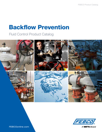
Series 757, 757NDouble Check Valve AssembliesSizes: 21 2" – 10" (65 – 250mm)1Double Check Valve Assemblies757 OSY (Vertical)757N BFG757 OSYSeries 757, 757N Double Check Valve Assemblies are used to prevent backflowof pollutants that are objectionable but not toxic, from entering the potablewater supply system. This Series can be applied, where approved by the localauthority having jurisdiction, on non-health hazard installations. The 757, 757Nmay be installed under continuous pressure service and may be subjected tobackpressure. The 757, 757N consist of two independently operating checkvalves, two shutoff valves, and four test cocks.FeaturesPressure – Temperature Extremely compact designTemperature Range: 33 F – 110 F(0.5 C – 43 C)Maximum Working Pressure: 175psi(12.1 bar) 70% lighter than traditional designs Groove fittings allow integralpipeline adjustment Patented tri-link checksprovide lowest pressure loss Unmatched ease of serviceability Available with grooved butterflyvalve shutoffs May be used for horizontal, verticalor N pattern installations Replaceable check disc rubberMaterials Housing & Sleeve: 304 (Schedule 40)Stainless Steel Elastomers: EPDM, Silicone and Buna-N Tri-link Checks: Noryl , Stainless Steel Check Discs: Reversible Silicone orEPDM Test Cocks: Bronze Body Nickel Plated Pins & Fasteners: 300 Series StainlessSteel#3 TestcockQuickAccessSleeveCorrosionResistant 300Series StainlessSteel Body andSleeveModelsSuffixNRS - non-rising stem resilient seatedgate valvesOSY - UL/FM outside stem and yokeresilient seated gate valves*OSY FxG - flanged inlet gate connectionand grooved outlet gate connection*OSY GxF - grooved inlet gate connectionand flanged outlet gate connection*OSY GxG - grooved inlet gate connectionand grooved outlet gate connectionBFG - 21 2" – 8" UL/FM grooved gearoperated butterfly valves with tamper switchQT - 21 2" – 3" quarter-turn, ball valvesTri-linkCheck ModulesReplaceableSeat DiscsAvailable with grooved NRS gate valves consult factory*Post indicator plate and operating nut available- consult factory**Consult factory for dimensionsApprovals Springs: Stainless Steel10154(BFG & OSY only)B64.5For additional information, request literature ES-757/757N.See Flow Charts on p. 70
Dimensions – WeightsJC(open)1IHAGP757, 757NSIZE (DN)DIMENSIONS (APPROX.)Ain.mm21 23468106580100150200250in.C (OSY)in. mmmm31 7873111 16 8053311 16 856431 2 110550 1270571 2 1460163 8187 8223 4301 8373 4453 44164795787659591162C (NRS)in.mm93 8101 4123 16161915 162313 16D238260310406506605Gin.mm31 2311 16451 2611 1683 168994102140170208in.WEIGHTHmmin.Immin.291 16 738 22 559 151 2301 4 768 223 4 578 171 833 838 24 610 181 2443 4 1137 333 4 857 233 16541 8 1375 405 8 1032 277 1666 1676 50 1270 321 2JPmmin.mmin.mm757NRSlbs. kgs.393435470589697826813 1693 16915 16131 161511 16175 1622323325233239944093 16101 2113 1615173 4199327757OSYlbs. kgs.757N NRSlbs. kgs.757N OSYlbs. 431IDAPHG757 BFG, 757N BFGSIZE (DN)DIMENSIONS .mmin.mmin.mmin.mm21 23468658010015020028281 2293 16361 2437117247419271092885 16815 1610121 420321122725431131 2311 16311 16561 2899494127165297 83011 163115 16433 16511 167597798111097129722223 424333 4405 855957861085710321415 16157 16161 41911 16235 16379392412500592813 1693 16915 16131 161511 16223233252332399991 210101 2143 16229241254267361757BFGlbs.kgs.757N BFGlbs. kgs.56542524646761117261285311884 38157 71337 1532930JCIDAPHG757 QTSIZE (DN)DIMENSIONS (APPROX.)Ain.12 23P1mmin.65801528 16303 16Cmmin.73576774 8413 16Dmmin.124122133 1637 8Gmmin.9798130 4301 4WEIGHTHmmin.768768124 2241 2Immin.622622916 16173 16Jmmin.421437311 8111 4Pmmin.289258710 16107 16P1mmin.mmlbs.kgs.2652655211217354516218 1689 16IMPORTANT: Inquire with governing authorities for local installation requirements5Double Check Valve AssembliesD
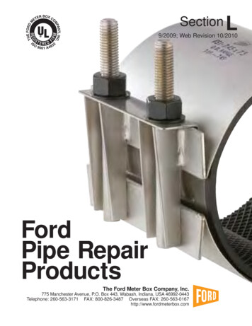
Series 757NaDouble Check Valve AssembliesSizes: 21 2" – 6" (65 – 150mm)1Double Check Valve Assemblies757Na BFGSeries 757Na Double Check Valve Assemblies are used to prevent backflow ofpollutants that are objectionable but not toxic, from entering the potable watersupply system. This Series can be applied, where approved by the local authority having jurisdiction, on non-health hazard installations. The 757Na may beinstalled under continuous pressure service and may be subjected to backpressure. The 757Na consist of two independently operating valves, two shutoffvalves, and four test cocks.FeaturesPressure – Temperature Extremely compact designTemperature Range: 33 F – 110 F(0.5 C – 43 C)Maximum Working Pressure: 175psi(12.1 bar) 70% lighter than traditional designs Groove fittings allow integralpipeline adjustment Patented bi-link checksprovide lowest pressure loss Unmatched ease of serviceability Available with grooved butterflyvalve shutoffs Used for N pattern installations Replaceable check disc rubberMaterials Housing & Sleeve: 304 (Schedule 40)stainless steel Elastomers: EPDM and Buna-N Bi-link Checks: Noryl , stainless steel Check Discs: Reversible EPDM Test Cocks: Bronze body nickel plated Pins & Fasteners: 300 Seriesstainless steel Springs: Stainless steelCorrosionResistant 300Series StainlessSteel Body andSleeveModelsSuffixNRS – non-rising stem resilient seatedgate valvesOSY – UL/FM outside stem and yokeresilient seated gate valves*OSY FxG - flanged inlet gate connectionand grooved outlet gate connection*OSY GxF - grooved inlet gate connectionand flanged outlet gate connection*OSY GxG - grooved inlet gate connectionand grooved outlet gate connectionBFG - 21 2" – 6" (65 – 150mm) UL/FMgrooved gear operated butterfly valves withtamper switchBi-linkCheck ModulesReplaceableSeat DiscsAvailable with grooved NRS gate valves - consult factory*Post indicator plate and operating nut available- consult factory**Consult factory for dimensionsApprovals10156#3 TestcockQuickAccessSleeve(BFG & OSY only)B64.5For additional information, request literature ES-757a/757Na.See Flow Charts on p. 70–71
Dimensions – WeightsIDouble Check Valve Assemblies1JHGP757NaSIZE (DN)DIMENSIONS 757Na NRSlbs.kgs.21 23466580100150291 16301 433443 4738768838113722223 424333 4559578610857151 2171 8181 2233 16393435470589813 1693 16915 16131 1622323325233293 16101 2113 1615234267284381123144184314566583142757Na OSYlbs.kgs.133158184336607283152Note: For 21/2" – 6" horizontal/vertical installation, see page 4-5.JIPHG757Na BFGSIZE (DN)DIMENSIONS 21 23466580100150297 83011 163115 16433 16759779811109722223 424333 45595786108571415 16157 16161 41911 16379392412500813 1693 16915 16131 16223233252332991 210101 2229241254267757Na BFGlbs.kgs.64672930841573871Note: For 21/2" – 6" horizontal/vertical installation, see page 4-5.IMPORTANT: Inquire with governing authorities for local installation requirements7
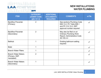
Series 774Double Check Valve Assemblies774: Sizes: 21 2" – 12" (100 – 300mm)1Double Check Valve Assemblies774 OSYSeries 774 and Double Check Valve Assemblies are designed to prevent thereverse flow of polluted water from entering into the potable water system.These models can be applied, where approved by the local authority havingjurisdiction, on non-health hazard installations. Series 774 feature short end-toend dimensions, light weight stainless steel body, and the lowest head lossavailable.TestcocksFeaturesMaterials Patented torsion spring check valveprovides low head loss All internal metal parts: 300 Seriesstainless steel Short lay length is ideally suited forretrofit installations Main valve body: 300 Seriesstainless steel Stainless Steel body is half the weightof competitive designs reducinginstallation and shipping cost Check assembly: Noryl Stainless steel construction provideslong term corrosion protection andmaximum strength Single top access cover with two-boltgrooved style coupling for ease ssure – TemperatureTemperature Range: 33 F – 110 F(0.5 C – 43 C) continuousMaximum Working Pressure: 175psi(12.1 bar)ReplaceableResilientSeatDiscCapturedTorsion Spring Laser Cut/PolishedCam Arm Thermoplastic and stainless steelcheck valves for trouble-free operation No special tools required for servicing Compact construction allows forsmaller vaults and enclosures May be installed in horizontal orvertical flow up position8For additional information, request literature ES-774 or ES-774X/774XDCDA.See Flow Charts on p. 72–73
Dimensions – Weights1C (open)MDLNPA774SIZE (DN)DIMENSIONS (APPROX.)Ain.mmin.mm21 2346810126580100150200250300383840481 2521 2551 2571 296596510161232133414101461C (open)in.mmC (NRS)in.mm163 8 41693 8187 8 479 101 4223 4 578 123 16301 8 76516373 4 959 1915 16453 4 1162 2313 16531 8 1349 263 4238260310406506605679STRAINER DIMENSIONSDGLPMmmin.mmin.mmin.mm.in.mmin.mm31 233 441 251 263 4891 81381222222271 2291 2291 2291 2559559559699749749749121 213141 2151 2181 4191 22131833036839446449553310101 2121 8181 2215 826297 825425730847054966075961 2781 4131 2151 2181 2213 4165178210343394470552ModelsSuffixNRS - non-rising stem resilient seatedgate valvesOSY - UL/FM outside stem & yokeresilient seated gate valvesLF - without shutoff valvesS - cast iron strainer*OSY FxG - flanged inlet gate connectionand grooved outlet gate 3103370104102170254346469w/o ls*OSY GxF - grooved inlet gate connection and flanged outlet gate connection*OSY GxG - grooved inlet gate connection and grooved outlet gate connectionAvailable with grooved NRS gate valves - consult factory*Post indicator plate and operating nut available- consult factory**Consult factory for dimensions1015(OSY only)(OSY only)For additional approvals consult factory.Flange dimension in accordance withAWWA Class DIMPORTANT: Inquire with governing authorities for local installation requirements9Double Check Valve AssembliesG
Series 709Double Check Valve AssembliesSizes: 21 2" – 10" (65 – 250mm)1Double Check Valve Assemblies709 OSYSeries 709 Double Check Valve Assemblies are designed to prevent the reverseflow of polluted water from entering into the potable water system. This Seriescan be applied, where approved by the local authority having jurisdiction, onnon-health hazard installations. Series 709 features a modular check designconcept to facilitate easy maintenance.FeaturesMaterials Replaceable bronze seats Maximum flow at low pressure drop Check Valve Bodies: Epoxy coated(FDA approved) cast iron Design simplicity for easy maintenance Seats: Bronze No Special Tools Required for Servicing Captured spring assemblies for safety Approved for vertical flow up installationCheck AssemblyModuleBoltedCoverPressure – TemperatureTemperature Range: 33 F – 110 F(0.5 C – 43 C) continuous, 140 F (60 C)intermittentMaximum Working Pressure: 175psi(12.1 bar)ResilientDisc10BV StyleTest CockFor additional information, request literature ES-709L.ReplaceableSeatSee Flow Charts on p. 68
C (Open)MDNRLAT709SIZE (DN)DIMENSIONS (APPROX.)Ain.21 2346810mmin.65 3980 40100 52150 631 4200 75250 90mm99110161321160719052286C(OSY)in.mm163 8187 8223 4301 8373 4453 4C(NRS)in.mm416 93 8479 101 4578 123 16765 16959 1915 161162 2313 16238260310406506605Din.3 1 23 3 44 1 25 1 26 5 88STRAINER DIMENSIONSLmmin.89 2495 24114 34140 421 2168 52203 64Rmmin.610 4610 5864 61089 111321 111 41626 121 2Tmmin.102 3127 3152 6279 71 2286 9318 101 4Mmmin.767615219122926010101 4121 8181 2215 826Nmmin.254 61 2260 7308 81 4470 131 2549 151 2660 181 2WEIGHT*N1mmin.165 10178 10210 12343 20394 223 4470 120037676167284545908*Dimensions needed for screen removal.ModelsSuffixNRS - non-rising stem resilient seated gatevalvesOSY - UL/FM outside stem and yokeresilient seated gate valvesLF - without shutoff valvesS-FDA - FDA epoxy coated strainerBB - bronze body 21 2" – 3" (65 – 80mm)QT - quarter-turn ball valvesQT-FDA - FDA epoxy coated quarter-turnball valvesApprovals1015(OSY only)AWWAApproved by the Foundation for CrossConnection Control and HydraulicResearch at the University of SouthernCalifornia.Sizes 4" – 10" (100 – 250mm) approvedhorizontal and vertical “flow up”Size 21 2" and 3" (65 and 80mm)approved horizontal only.Factory Mutual approved 4" – 10"(80 – 250mm) vertical “flow up”IMPORTANT: Inquire with governing authorities for local installation requirements11Double Check Valve Assemblies1Dimensions – Weights
Series 007Double Check Valve AssembliesSizes: 1 2" – 3" (15 – 80 mm)1Double Check Valve Assemblies32" 007M1QT HC 4" 007M3QTSeries 007 Double Check Valve Assemblies shall be installed at referencedcross-connections to prevent the backflow of polluted water into the potablewater supply. Only those cross-connections identified by local inspectionauthorities as non-health hazard shall be allowed the use of an approved doublecheck valve assembly.FeaturesModels Ease of maintenance - only one cover1 Top entrySuffixQT - quarter turn ball valvesLF - without shutoff valvesLH - locking handle ball valves (openposition)SH - stainless steel ball valve handlesHC - 21 2" inlet/outlet fire hydrantfitting (2" valve)S - bronze strainerPC - polymer coating Replaceable seats and seat discs Modular construction Compact design Top mounted ball valve test cocks Low pressure drop No special tools required for servicing 1 2" – 1" (15 – 25 mm) have tee handles 2" – 2" (15 – 50mm) 1 2" – 2" (15 – 50mm) cast bronze bodyconstructionPrefixU - union connections 21 2" – 3" (65 – 80mm) fused epoxycoated cast i
replaceable for repair and testing. Cross-connection where there is a non-health hazard. Residential Supply Lines (at the meter) Residential fire sprinkler systems Post-Mix beverage machines, tea and coffee machines SPECIALTY BACKFLOW PREVENTERS with INTERMEDIATE ATMOSPHERIC VENT For non-health hazard cross-connections in small pipe sizes .