Transcription
OBD II Data InterpretationWhat is OBDII?OBDII stands for on board diagnostics second generation superseding that ofOBD1.OBDII is a system that was mandated by the Federal EPA and was developed bythe society of automotive engineers (SAE). Its purpose is to standardize automotiveelectronic diagnostics so technicians can use the same scan tool to test all makes andmodel of automobiles without special adapters and or factory scanners. When the EPAmandated OBD11 computer systems, they also mandated that all manufactures wouldmake available generic information that would be the same for all manufactures. Theyalso mandated that anybody's scanner could have access to the computer system withthe proper software and adapters. This information would have the same codeterminology, data parameters, freeze frame data and system monitors. Updatedscanner software will usually have OBDII generic mode capabilities. It will access anymanufactures OBDII generic mode and allow you to retrieve codes, data, monitorinformation and freeze frame data without having to buy specific software for thatmanufacturer. For example, you may only have software for a GM if this software hasthe OBDII generic mode you would be able to use it on a NISSAN. OBDII vehicles werefirst introduced in year 1994 by the year 1996 all vehicles sold in the united states wererequired to be outfitted with OBDII complaint computer systems.OBDII computer system require standardization of:Universal diagnostic test connector known as the data link connector (DLC) withdedicated pin assignmentA standardized location for the DLC usually located under the dash on the driver’s side.A standardized list of generic diagnostic trouble codes used by all manufactures.The ability of the computer system to record a frame of data as a fault occurs within thecomputer system known as "freeze frame" data.Expanded diagnostic capabilities that record a code whenever a problem occurs thataffects the emissions.The ability to clear all hard and pending codes with a scan tool.A standardization of acronyms and definitions used for system components.Data parameters(HO2S sensor monitors) this information is available in the codes and data area of thescan tool. This selection allows you to dissect the output of the HO2S (heated oxygen
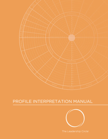
sensor) voltage by breaking it down to maximum voltage output, minimum voltageoutput and switching rate. The computer looks to see if the HO2S voltage rises above600 MV and falls below 300 MV and switches in less than 100 milliseconds. The PCMwill provide a rich or lean mixture to test the HO2S ability to rise above and below thevoltage levels it's looking for. The PCM also looks at the reaction time to make sure theHO2S is not lazy. Testing of the HO2S this way assures that the catalytic converter willremain efficient. When the catalytic converter is working properly the computer seesalmost no switching action from the rear o2 sensor. To test the rear O2 sensor thecomputer will force a rich or lean mixture that the catalytic converter can't compensatefor and then monitors the HO2S voltage.There are nine sensor tests available on OBDII vehicles.Rich to lean threshold voltage. .Lean to rich threshold voltage.Low sensor voltage for switch time calculation.High sensor voltage for switch time calculation.Rich to lean sensor switch time.Lean to rich sensor switch time.Minimum sensor voltage for test cycle.Maximum sensor voltage for test cycle.Time between sensor transitions. Below is an illustration of the different test points.AIR injection (range upstream/downstream/atmosphere)This parameter allows us to view the status of the air injection whether it is upstream,downstream or bypassing to the atmosphere. The normal state of operation is asfollows: When the car is cold and in open loop the air should be in the upstream mode.This allows air to be dumped into the exhaust manifold to quicken O2 sensor heat uptime and to oxidize HC that's in the hot exhaust. When the engine is hot and in closedloop the air will go down stream into the catalytic converter to allow it to oxidize. Ondeclaration the air should move to the atmosphere mode to prevent the possibility ofbackfire. Under no circumstances should the air injection be in the upstream modewhen the engine is in closed loop. While in closed loop the O2 sensor is the primarysensor for air/fuel mixture control. Since the O2 sensor's only job is to monitor oxygen inthe exhaust, any air flowing past it from the air injection would cause the O2 sensor togive a false lean signal. The PCM would richen the mixture in response to it.Airflow grams per second (range low at idle and increase with engine load)This parameter displays a calculated value of airflow across the MAF. The MAF thensends a varying signal output to the PCM that is calculated as grams per second, cubicmeters per hour, or kilograms per hour. Most MAF sensors have a hot wire thatstretches across the front of the sensor that is heated up to a certain temperature. Asthe throttle plate is opened, the air rushes past the wire and cools it off. The internalcircuitry of the MAF sensor will then put more current to the wire to keep it at the sametemperature. This will allow the sensor to generate a signal based on the current it tookto keep the wire at the same temperature. The PCM will receive this signal andcalculate mass airflow. If the wire is dirty it can skew the measurement of mass airflow
and cause a biased rich or lean condition. This condition does not always set a code forthe MAF. Note: an important fact to remember if the vehicle has a hard code for a MAF,the scanner will still display a changing value for the MAF parameter. While the MIL lightis on the vehicle will be in limp home mode and the value that is observed on thescanner is a made up value based on RPM, TPS and look up tables within the PCM.Coolant temp sensor (range -40 to 389 F)The CTS (coolant temperature sensor) is an NTC (negative temperature coefficient)thermistor that creates varying degrees of voltage drop on a 5-volt reference wire that'ssupplied by the PCM. The PCM will interpret the voltage drop on the 5-volt referencewire and convert these voltage changes into temperature readings and display it on thescanner. When the sensor is unplugged, the open circuit from the PCM will be reading 5volts on the CTS wire and display -40 degrees on the scanner. When the CTSconnector is jumped short circuit, the PCM will be reading "0" volts on the wire anddisplay a reading of 389 degrees. Normal operating range for the sensor, when hot,should be 185 to 220 degrees. Voltage will be 3 volts cold .5 volts hot. This sensor hasa major influence over fuel mixture when the engine is cold. Its influence diminishes asthe engine warms up to operating temperature. The CTS and ACT readings should becompared when dealing with a cold start problem make sure they are within 10 degreesof each other when the engine is cold. The PCM also uses the CTS input to control thecooling fan operation, on some vehicles. The PCM will turn on the fan if it senses anopen or shorted CTS circuit. This is a fail-safe mode of operation to protect the motorfrom damage due to overheating. CTS is also used by the PCM to determine when toactivate the torque convert clutch.Engine rpmRPM is a measurement of engine speed. This information comes to the PCM from thecrank sensor or ignition system. RPM is the only input that the PCM cannot substitute.RPM is the most important input to the PCM, without it the engine will not run. On somemanufactures the rpm will display on the scanner while in the crank mode this, can be auseful tool when diagnosing no start problems. If there is an RPM signal while in thecrank mode, the crank sensor and or ignition module must be sending distributorreference so don't look there for the no start problem. The PCM uses RPM to pulse theinjectors and make the ignition coil fire. RPM is used by the PCM to control torqueconverter clutch operation. On computer controlled transmission the PCM will use theRPM in conjunction with the turbine and output shaft speed sensors to control shiftingand determine transmission slippage.Fuel pressure (range 0 to 112 PSI)This input comes to the PCM from a pressure sensor on the fuel rail. This input can beextremely useful in diagnosing intermittent fuel pressure problems that affectderivability. The fuel pressure specs very from manufacturer to manufacture so consulta service manual for exact specs. One of the best features of this parameter is the fuelpressure can be observed while driving the vehicle. The best volume test of a fuel pumpis done while the vehicle it at wide-open throttle (WOT). When at WOT the PCM iscommanding the richest mixture. The injectors are being held open for a long period of
time if the pressure drops at this time it means the fuel pump can’t keep up with thesupply demand, determining the fuel pump is bad, the fuel filter is restricted or a linerestriction could be causing the problem.Fuel system status (range open loop or closed loop)Fuel status bank 1Fuel status bank 2This parameter displays the status of the fuel system whether it is in closed loop oropen loop. The term open loop means that the PCM is not using the O2 sensor signalvoltage to influence the air fuel mixture. The term closed loop means that the O2 sensorsignal voltage is directly influencing the air fuel mixture. When the engine is cold the fuelstatus will be open loop, as the engine reaches normal operating temperature the fuelstatus should switch to closed loop. It takes three occurrences to allow a vehicle toenter closed loop, engine at predetermined temperature, O2 sensor switching and theinternal timer within the PCM has to time out. The vehicle can fall back to open loop forvarious reasons, WOT, deceleration, a hard code, O2 sensor heater circuit failure,sticking thermostat.Ignition timing (range plus or minus)This parameter displays the amount of timing the PCM is adding or subtracting frombase timing. The PCM uses sensor inputs to determine where to put the timing. Whenthe engine is under a heavy load it will retard the timing to keep the engine fromdetonation. On decal the timing will advance. When a sensor such as a MAP sends alean command signal to the PCM the timing will advance or vice versa when it sends arich command signal the timing will retard. A sensor that is biased in either direction willhave a drastic effect on timing advance.Intake air temp sensor (range -40 to 389 degrees F)The ACT (air charge temperature) sensor is a (NTC) thermistor that creates varying degrees ofvoltage drop on a 5-volt reference wire that's supplied by the PCM. The PCM will interpret thevoltage drop on the 5-volt reference wire and convert these voltage changes into temperaturereading and display it on the scanner. When the sensor is unplugged (open circuit) the PCM willbe reading 5 volts on the ACT wire and display -40 degrees on the scanner. When the ACTconnector is jumped short circuit the PCM will be reading "0" volts on the wire and display areading of 389 degrees. Normal operating range for the sensor when hot should be 75 to 110degrees. Voltage will change with airflow across the sensor. Changes in air temperature affectair fuel mixture. When the ambient temperature is hot the air is thin and the system would berich. The opposite is true when the ambient temperature is cold the air is dense the mixturewould be lean. The PCM will compensate for air temperature changes and change the air fuelmixture. This sensor is not a high priority sensor; its influence over air fuel mixture is not like theCTS. The CTS and ACT reading on the scanner should be compared when dealing with a coldstart problem make sure they are within 10 degrees of each other when the engine is cold.Engine load (range 0 to 100%)This parameter indicates the actual load of the engine by dividing the actual manifold airflowvolume by the maximum possible manifold airflow volume, the higher the number the heavierthe load. This parameter will usually be around 2% at idle and increase with engine load to as
high as 100%. It is common on some manufactures to have a high load value at idle when thereis a MAF sensor circuit failure. Example: a poor ground on the MAF sensor will allow the sensorto output a higher voltage signal than the actual load of the engine. This will be interpreted bythe PCM as a load condition and the PCM will richen up the mixture. OBDII will also look at thesensor reading and determine if it is rational. If it is not, a fuel trim code might be set.Long term fuel trim bank 1 and bank 2 (range -25% to 25%)Note: bank one is where #1 cylinder is located.This parameter displays information on the fuel correction status of the PCM over the long term.0% represents the mid-point. Any number less than 0% indicates the PCM is leaning out the airfuel mixture with less injector on time. Numbers greater than 0% indicate the PCM is richeningthe air fuel mixture with increased injector on time. The purpose of the long term fuel trim is tokeep the short term fuel trim averaging 0% it will move in either direction to achieve this goal. Ifthe PCM is successful in achieving this goal the air fuel ratio will be around 14.7 to 1. The longterm fuel trim operates only in closed loop operation. In open loop it reverts the learned value itcreated while in closed loop operation.Map sensor (range 0 to 60 HG)This parameter displays manifold absolute pressure reading from the MAP sensor voltagesignal. This parameter should be about 29.6 inch., with the engine not running at sea level andabout 9.6 in. hg. while the engine is at idle. The engine runs at about 20 inches vacuum at idleso subtract 20 from 29.9 and this gives us 9.6 in.hg. of pressure in the intake. As the engine isplaced under a load the pressure will increase to as high as 29.6 at wide open throttle. Keep inmind the scanner is displaying pressure not vacuum
A standardization of acronyms and definitions used for system components. Data parameters (HO2S sensor monitors) this information is available in the codes and data area of the scan tool. This selection allows you to dissect the output of the HO2S (heated oxygen