Transcription
03/2016112495.503159NEMA 7/9 HOISTFMAPPROVEDWITH EXCLUSIVE FEATURES:TROLLEYCLASSES:FLAMMABLE GASESCLASS 1, DIVISION 1, GROUP D, T2CCOMBUSTIBLE DUSTCLASS II, DIVISION 1, GROUP F & G, T2CPROPER APPLICATIONDoor TypeSectional(All Types)Rolling Steel(All Types)Operator TypeHoist(Sidemount,Centermount,Chain or Direct Couple)Hoist(Front of Hood,Top of Hood, orBench Mount)HP/Max Door WeightPROPER APPLICATION1/2HP 1310 lbs.1HP 1650 lbs.3HP 3696 lbs.Door TypeSectional(Standard orLow HeadroomTrack Only)Operator TypeTrolley(Standard, Sidemountor Dual Trolley)HP/Max Door Weight1/2HP 1310 lbs.1HP 1650 lbs.NOT FOR RESIDENTIAL USEThis Installation Manual provides the information required to install, troubleshoot andmaintain an RHX NEMA 7/9 Commercial/Industrial Door Operator.
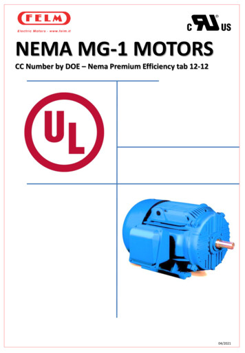
Typical InstallationHOISTAA Motor FeedUp to 7 Wires. Explosion ProofConduit not included.BB Limit Switch/InterlockLow Voltage Intrinsically SafeFeed. Up to 5 wires.CC Power Input FeedUp to 4 Wires. Explosion ProofConduit not included.D Safety FeedLow Voltage Intrinsically SafeFeed. 2 wires.E NEMA 7/9 ExplosionProof EnclosureF 3-Button StationLow Voltage Intrinsically SafeFeed. 4 wires.FG Limit Switch/SafetyFeed Junction BoxEDGLow Voltage IntrinsicallySafe FeedHH Factory InstalledIntrinsically Safe ControlWire Junction Box.!WARNINGEnd User/ Installer MUST follow applicableNEC requirements along with Localrequirements for Hazardous Wiring.!AVERTISSEMENTIl appartient à l’utilisateur final / installateur derespecter les exigences du NEC et les exigenceslocales pour le câblage en site dangereux.
Table of ContentsSection 1How to use this manual. 1.1Section 2Safety Information & Instructions.2.1-2.2Section 3Critical Installation Information.3.1-3.3Section 4InstallationDoor Sizing. 3.4Rolling Steel Weld Plate . 4.1Rolling Steel Top of Hood/Front of Hood. 4.2Rolling Steel Bench Mount. 4.3Rolling Steel/Sectional Wall Mount. 4.4Sectional Door Direct Couple . 4.5Sectional Door Center Mount. 4.6Manual Handwheel/Release Cord. 4.7Optional Clutch/Vent Plug. 4.8Trolley Model Installation. 4.9-4.16Clutch/Vent Plug.4.17Limit Switch Assembly Reversal.4.18Enclosure Mounting.4.18Section 5WiringSection 6Operator ConfigurationTypical Installation Diagram . 5.1Line Voltage & Motor Wiring. 5.2-5.4Intrinsically Safe Wiring .5.5-5.9Circuit Board Switch Diagram. 6.1Setting Close Direction and Limit Orientation .6.2Setting Limits. 6.3Setting Limit Overrun . 6.4Setting Momentary and Constant Contact. 6.5Setting Wall Button . 6.6Max Run Timer. 6.6Setting Timer to Close, 3 Strikes Feature. 6.7Section 7Cycle Count, Operator Status &TroubleshootingCycle Count. 7.1Status Display. 7.2Section 8Service & Maintenance . 8.1Section 9Appendix A, Parts BreakdownsHoist Operator (1/2 & 1HP). 9.1Hoist Operator (3HP). 9.2Hoist Shaft Assembly. 9.3Trolley Operator. 9.4Trolley Output Shaft Assembly. 9.5Trolley Rail Assembly. 9.6NEMA 7/9 Enclosure Parts. 9.7Mounting Kits . 9.8Section 10 Warranty Information.10.1
Section 1: How to use this ManualThe 10 sections of this Installation Manual provide the information required to install, troubleshoot and maintain an RHX NEMA 7/9commercial/industrial door operator.Section 2Provides important defining information related to safety terminology used throughout this manual, as well as safety related instructionswhich must be followed at all times while doing any steps/tasks/instructions detailed in this manual.Section 3Details pre-installation concerns/issues/decisions that are recommended to be considered and/or resolved prior to beginning any commercial door operator installation.Sections 4-6Provides step by step installation and set-up instructions for the NEMA 7/9 commercial door operator. Each section is written such that itmust be followed in a step by step order to complete a successful installation.WARNINGFailure to correctly perform all steps in sections 4-6 can result in serious injury or death.AVERTISSEMENTNe pas effectuer correctement toutes les étapes dans les sections 4-6 peut entraîner desblessures graves voire la mort.Section 7Details important features and troubleshooting information for typical installation and normal operations that may occur.Sections 8-10Provides related information on service and maintenance items, operator drawings for use in troubleshooting and service activities, alongwith important warranty and returned goods policy information.1.1
Section 2: Safety Information and Instructions!WARNINGIMPORTANTOverhead Doors are large, heavy objects that move with the help of springs under high tensionand electric motors. Since moving objects, springs under tension, and electric motors can causeinjury, your safety and the safety of others depend on you reading the information in this manual. Ifyou have any questions or do not understand the information presented, call your nearest servicerepresentative. For the number of your local Overhead Door Dealer, call 800-929-3667, and forOverhead Door Factory Technical Advice, call 800-275-6187.In this manual the words Danger, Warning, and Caution are used to stress important safetyinformation. The word:DANGER indicates an imminently hazardous situation which, if not avoided, will result in!death or serious injury.WARNING indicates a potentially hazardous situation which, if not avoided, could result in!death or serious injury.CAUTION indicates potentially hazardous situation which, if not avoided, may result in injury!or property damage.The word NOTE, is used to indicate important steps to be followed or important considerations.POTENTIAL HAZARDMOVING DOORELECTRICAL SHOCKEFFECT! WARNINGCould result in SeriousInjury of Death! WARNINGCould cause SeriousInjury or DeathHIGH SPRING TENSION! WARNINGCould cause SeriousInjury or DeathREAD PRIOR TO ANY DOOR OPERATION1.2.3.4.5.PREVENTIONDo Not operate unless the doorway is in sight and free ofobstructions. Keep people clear of opening while door is moving.Do Not allow children to play with the door operator.Do Not change operator control to momentary contact unless andexternal reversing means is installed.Do Not operate a door that jambs or one that has a broken spring.Turn off electrical poser before removing operator cover.When replacing the cover, make sure wires are not pinched or nearmoving parts.Operator must be electrically grounded.6.7.Read manual and warnings carefully.Keep the door in good working condition.Periodically lubricate all moving parts of door.If door has a sensing edge, check operationsmonthly. Make any necessary repairs to keep itfunctional.AT LEAST twice a year, manually operate thedoor by disconnecting it from the operator.The Door should open and close freely. If itdoes not, the door must be taken out of serviceand a trained service representative mustcorrect the condition causing the malfunction.The Operator Motor is protected againstoverheating by an internal thermal protector.If the motor protector is tripped, a trainedservice technical may be needed to correct thecondition which caused the overheating. Whenthe motor has cooled, thermal protector willautomatically reset and normal operation canbe resumed.In case of power failure, the door can beoperated manually by pulling the release cableto disconnect the operator drive system.Keep instructions in a prominent location nearthe pushbutton.Do Not try to remove, repair or adjust springs or anything to whichdoor spring parts are fastened, such as wood block, steel bracket,cable or any other structure or like item.Repairs and adjustments must be made by trained servicerepresentative using proper tools and instructions.2.1
Section 2: Safety Information and Instructions!AVERTISSEMENTLes portes basculantes sont de gros objets lourds qui fonctionnent à l’aide de ressorts soumis à unehaute tension et de moteurs électriques. Dans la mesure où les objets en mouvement, les ressortssous tension et les moteurs électriques peuvent entraîner des blessures, votre sécurité et celle desautres exigent que vous preniez connaissance des informations stipulées dans ce manuel. Si vousavez des questions ou si vous ne comprenez pas les informations ci-incluses, veuillez contacter lereprésentant de service le plus près. Pour obtenir le numéro du revendeur Overhead Door local,appelez le 1 (800) 929-3667, et pour obtenir des conseils techniques de l’usine Overhead Door,appelez le 1 (800) -275-6187.Dans ce manuel, les mots Danger, Avertissement, et Attention sont utilisés pour faire ressortird’importantes informations relatives à la sécurité. Le mot :! DANGER signale une situation dangereuse imminente qui si elle n’est pas évitée, risque d’entraînerdes blessures graves, voire mortelles.! AVERTISSEMENT signale une situation potentiellement dangereuse qui, si elle n’est pas évitée, risqued’entraîner la mort ou des blessures graves.! ATTENTION signale une situation potentiellement dangereuse qui, si elle n’est pas évitée, risqued’entraîner des blessures ou des dommages matériels.Le terme REMARQUE est utilisé pour signaler les étapes importantes à suivre ou d’importants élémentsà prendre en considération.DANGER POTENTIELPORTE EN MOUVEMENTEFFET! AVERTISSEMENTPourrait entraîner desblessures graves voire la mortCHOC ÉLECTRIQUE! AVERTISSEMENTCouper le courant avant d’enlever le couvercle de l’opérateur.Lorsque le couvercle doit être remplacé, s’assurer que les fils ne sontni coincés ni près des pièces mobiles.L’opérateur doit être correctement mis à la terre.! AVERTISSEMENTNe pas essayer d’enlever, réparer ni ajuster les ressorts outoute autre pièce à laquelle le ressort de la porte est attaché, ycompris blocs de bois, supports en acier, câbles ou autres articlessemblables.Les réparations et les réglages doivent être effectués partechnicien qualifié qui se sert d’outils appropriés et qui respecte lesinstructions.Pourrait entraîner desblessures graves voire la mortTENSION ÉLEVÉE RESSORTPRÉVENTIONUtiliser uniquement si la porte est en vue et libre de tout obstacle.Ne laisser personne se tenir dans l’ouverture de la porte pendantqu’elle est en mouvement.Ne pas permettre aux enfants de jouer avec l’opérateur de la porte.Ne pas modifier la commande de l’opérateur à contact momentanéà moins qu’un moyen d’inversion externe soit installé.Ne pas faire fonctionner une porte qui bloque ou dont le ressortest cassé.Pourrait entraîner desblessures graves voire la mort2.2
Section 3: Critical Installation InformationJob Site Issues to Consider/ConcernsThe following list of items should be considered prior to selecting an operator for a given job site.1-Available power supply. 2-Type of door. 3-Potential operator mounting obstructions. Reversal of Limit Box (4.18). Items to consider include, but are not limited to: side room,room above door shaft, room below door shaft, available mounting surface integrity, power supply location, and convenient chain hoist and release cable positioning. 4-Sizeof door for appropriate operator torque and door travel speed selection. 5-Door activation needs/requirements. Examples include 3 button control stations, 1 button controlstations, pull cords, key switches. 7-Interlock switches are required under certain conditions for doors with pass doors and door locks. See Section 5.7. 8-Accessory equipment.Examples include reversing edges which are required for doors set to operate as momentary contact, etc. See “Entrapment Protection” section below.! ENTRAPMENT PROTECTIONThe installation of a monitored external reversing edge is required on all momentary contact electronically operated commercial doors. If such a reversing device is notinstalled, the operator will revert to a constant contact control switch for operation (Closing only).The Reversing Devices currently UL Approved are:1). MillerEdge ME T2 and MT T2 Series monitored edge sensors.!WARNING: DO NOT apply line voltage until instructed to do so.!AVERTISSEMENT: NE PAS mettre sous tension tant que l’instruction n’est pas donnée de le faire.3.1
Section 3: Critical Installation Information!CAUTION: Check working condition of door before installing the operator. Door must be free from sticking and binding. If equipped, deactivate any doorlocking device(s). Door repairs and adjustments, including cables and spring assemblies MUST be made by a trained service representative using proper tools andinstructions.!ATTENTION: Vérifiez l’état de fonctionnement de la porte avant d’installer l’opérateur. La porte doit pouvoir bouger librement et ne pas coincer. Désactiveztous les dispositifs de verrouillage de la porte (si équipés). Les réparations et les réglages de porte, plus particulièrement pour les câbles et les ressorts DOIVENTêtre effectués par un technicien qualifié qui se sert d’outils appropriés et qui respecte les instructions.IMPORTANTINSTALLATION INSTRUCTIONSWARNINGTo reduce the risk of severeinjury or death:1.2.3.4.5.6.7.8.READ AND FOLLOW ALL INSTALLATION INSTRUCTIONS.Install only on a properly operating and balanced door. A doorthat is operating improperly could cause severe injury. Havequalified service personnel make repairs to cables, springassemblies and other hardware before installing the operator.Remove all pull ropes and remove, or make inoperative, alllocks (unless mechanically and/or electronically interlockedto the power unit) that are connected to the door beforeinstalling the operator.Install the door operator at least 8 feet above the floor if theoperator has exposed moving parts.Do not connect the door operator to the power source untilinstructed to do so.Locate the control station: (a) within sight of the door, (b)a minimum of 5 feet above the floor so that small childrencannot reach it, and (c) away from all moving parts of thedoor.Install the Entrapment Warning Placard next to the controlstation and in a prominent location.For products having a manual release, instruct the end user onthe operation of the manual release.IMPORTANTINSTRUCTIONS D’INSTALLATIONAVERTISSEMENTPour réduire les risques deblessures graves ou de mort :1.2.3.4.5.6.7.8.LIRE ET RESPECTER TOUTES LES INSTRUCTIONS D’INSTALLATION.Installez uniquement sur une porte fonctionnant correctementet bien équilibrée. Une porte qui fonctionne mal peutprovoquer des blessures graves. Demandez à un technicienqualifié d’effectuer les réparations des câbles, des ressorts et detoute autre quincaillerie avant de procéder à l’installation del’opérateur.Retirez toutes les cordes de traction ainsi que tous les verrous ourendez-les inopérants (à moins qu’ils ne soient mécaniquementet/ou électroniquement interverrouillés à l’unité motrices) quisont connectés à la porte avant de procéderà l’installation del’opérateur.Installez l’opérateur de la porte à 2,4 m minimum au-dessus dusol lorsque des pièces mobiles de l’opérateur sont exposées.Ne pas raccorder l’opérateur de la porte à la source d’alimentationavant que l’instruction ne soit donnée de le faire.Installez la station de commande : (a) en vue de la porte, (b) à1,5 m minimum au-dessus du sol pour que les jeunes enfantsne puissent pas l’atteindre, et (c) à l’écart de toutes les piècesmobiles de la porte.Installez le poster d’avertissement de pincement à côté de lastation de commande à un endroit bien en vue.Pour les produits ayant un déclenchement manuel, indiquez àl’utilisateur comment déclencher manuellement.3.2
Section 3: Critical Installation InformationIMPORTANTSAFETY INSTRUCTIONSWARNINGTo reduce the risk of severeinjury or death:CONSIGNESDE SÉCURITÉ IMPORTANTESAVERTISSEMENTPour réduire les risques deblessures graves ou de mort :1) READ AND FOLLOW ALL INSTRUCTIONS.2) Never let children operate or play with door controls. Keep theremote control (where provided) away from children.3) Personnel should keep away from a door in motion and keep the moving doorin sight until it is completely closed or opened. NO ONE SHOULD CROSS THEPATH OF A MOVING DOOR.4) Test the door’s safety features at least once a month. After adjusting either theforce or the limit of travel, retest the door operator’s safety features. Failure toadjust the operator properly may cause severe injury or death.5) For products having a manual release, if possible, use the manual release onlywhen the door is closed. Use caution when operating the release while the dooris open. Weak or broken springs may cause the door to fall rapidly, causingsevere injury or death.6) KEEP DOOR PROPERLY OPERATING AND BALANCED. See Door Manufacturer’sOwner’s Manual. An improperly operating or improperly balanced door couldcause severe injury or death. Have only trained door systems technicians makerepairs to cables, spring assemblies, other hardware and any wooden blocksor like items to which they may be attached.7) SAVE THESE INSTRUCTIONS.1) LIRE ET RESPECTER TOUTES LES INSTRUCTIONS.2) Ne jamais permettre aux enfants d’actionner ni de jouer avec les commandes de la porte.Tenir les télécommandes (si fournies) hors de la portée des enfants.3) Le personnel doit se tenir à l'écart d'une porte en mouvement et garder bien en vue une porte en mouvementjusqu'à ce qu'elle soit complètement fermée ou ouverte. PERSONNE NE DOIT TRAVERSER LA TRAJECTOIRED'UNE PORTE EN MOUVEMENT.4) Testez les fonctionnalités de sécurité de la porte au moins une fois par mois. Après avoir régléla force ou la limite de la course, retestez les éléments de sécurité de l’opérateur de la porte. Un mauvais réglagede l’ouvre-porte peut entraîner des blessures graves voire la mort.5) Pour les produits ayant un déclenchement manuel, dans la mesure du possible, utilisez le déclenchement manueluniquement lorsque la porte est fermée. Prenez toutes les précautions nécessaires lors de l'utilisation dudéclenchement manuel alors que la porte est ouverte. Des ressorts faibles ou brisés peuvent faire descendrela porte rapidement ce qui peut entraîner des blessures graves voire la mort.6) VEILLER À CE QUE LA PORTE SOIT CORRECTEMENT ÉQUILIBRÉE ET FONCTIONNE BIEN. Consultez le manuel del’utilisateur du fabricant de la porte. Une porte déséquilibrée ou fonctionnant incorrectement pourrait entraînerde graves blessures voire la mort. Seuls des techniciens formés sur systèmes de portes peuvent effectuer desréparations aux câbles, aux ressorts, aux autres matériels et aux blocs de bois ou élémentssemblables auxquels ces éléments peuvent être attachés.7) CONSERVER CES CONSIGNES.3.3
Section 3: Critical Installation InformationRHX Sectional Door Chart (Sq. Ft.) HOISTDoor Series - ModelHPMountingTypeMax. DoorWeight(Lbs)Commercial Steel Insulated & teelInsulated326326591592593RibbedSteel1 5/8"RibbedSteel 2"RibbedSteel1 1 3/8"20GA.FlushSteel1 5/8"RibbedSteel1"FlushSteel 2"RHX 8RHX HX 14 RPM irect1SCCoupleKitRHX 14 RPM 448Direct3SCCoupleKitS Jackshaft, Side Mount, C Jackshaft, Center MountNOTE: Side/Center direct couple kit output speed is 26RPM for 1/2 and 1 HP. For larger doors use 14 RPM output speed direct couple kit on 1HP and 3HP RHX operators.NOTE: Total door weight, and not the square footage, is the critical factor in selecting the proper operator. Square foot measurments are based on "Square Doors". (Example 16' X 16')NOTE: Doors that require special wind loading and wide doors normally require strutting(reinforcement). Strutting doors can significantly increase door weight beyond maximum weight shown. Consult factory511521326326406526326526326526RHX Rolling Steel Door Chart (Sq. Ft.)ModelHP600Rolling Steel Doors610/620610Coilaway 24GA.22GA.20GA.18GA.Rolling Fire Doors / Fire ShuttersCounter RHX 256*4654033512682472151RHX 600523399367320256*6903RHX 1137945867798696256*N/ANote: Door chart represents max. door height of 24ft., over 24ft high consult factory.* Operator must be wall .22GA.22GA. / ALL*ALL*ALL*5407001080240340888RHX Trolley Sectional Door Chart (Sq. Ft.)416418Commercial Steel Insulated & Non-Insulated420422424426ModelHPMax. RibbedSteelRHX 1 3/8"RaisedPanelSteel1 3/8"20GA.FlushSteel1 5/8"RibbedSteel1"FlushSteel RibbedSteel1 5/8"RibbedSteel 326326501RHX 1NOTE: Total door weight, and not the square footage, is the critical factor in selecting the proper operator. Square foot measurments are based on "Square Doors". (Example 16' X 16')NOTE: Doors that require special wind loading and wide doors normally require strutting(reinforcement). Strutting doors can significantly increase door weight beyond maximum weight shown. Consult factory3.4
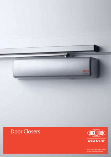
Section 4: Installation - HoistRolling Steel - Front of Hood & Top of Hood Mount Weld Plate AttachmentHPREQUIRED MOUNTING KIT1/2, 1 ROLLING STEEL - FOH-TOH3ROLLING STEEL - FOH-TOHPART NUMBEROPMKRSHX.SOPMKRSHX3HP.SNOTE: If installation will require the reversal of the limit box, refer topage 4.181) Determine operator mounting location, including desiredhoist and release location and release cable routing.2) Weld the Rolling Door weld plate assembly to the doorheadplate, a minimum of two 1” weld beads are required oneach side of the weld plate for proper attachment. See Fig 1for proper placement.REFER TO SHOP DRAWINGS FORSPECIFIC DIMENSIONING INFORMATIONFigure 1 WELD PLATE ATTACHMENT1/4”P/N 110010.0001.SWELD TO HEADPLATE.MIN. (2) 1/4” X 1” WELDBEADS ON EACH SIDEOF BRACKET.9”“A”DIM1/4”P/N 110010.0001.SWELD TO HEADPLATE.MIN. (2) 1/4” X 1” WELDBEADS ON EACH SIDEOF BRACKET.1/4”HEADPLATESIZEWELD BEADS TOBE ALONG THISEDGE ON BACKSIDE OF BRACKET(IF BRACKET EXTENDSBEYOND HEADPLATE)FRONT OF HOODHEAD PLATE DETAIL(STANDARD WELD BRACKET LOCATION)(14” HEADPLATE & LARGER)14” FOH only16” FPH only18”20”22”24” & LARGER“A” DIM(1/2-1 HP)4 1/8”5 1/8”6 1/8”7 1/8 ”9 1/4”“A” DIM(3 HP)-9 1/4”TOP OF HOODHEAD PLATE DETAIL(18” or larger 1/2-1hp, 24” for 3hp)(STANDARD WELD BRACKET LOCATION)4.1
Section 4: Installation - HoistRolling Steel - Front of Hood & Top of Hood MountFigure 2The RHX Rolling Steel Operators are factory assembled for righthand mounting (shown). Each model can also be converted toleft-hand mount See page 4.7 for instructions.1) Attach operator to main mounting bracket using the four3/8”-16 x 1-1/2” bolts, hex nuts, and lock washers. See Fig 2.NOTE: For 3 HP units, 1/2”-13 x 2-1/2” bolts are required.2) Mount the operator to the weld plate using the 7/16”-14 hexnuts. Hand tighten bracket to weld plate nuts.Attach Operator to Door: Fig. 3.3) Attach 12 tooth sprocket to operator output shaft.4) Align keyways and insert key into sprocket and output shaftkeyway. Do not tighten set screw at this time.5) Attach door sprocket to door shaft. Align keyway and insertkey. Do not tighten set screws at this time.6) Assemble chain using chain master link.7) Place assembled chain over door shaft sprocket and aroundthe 12 tooth sprocket and align.8) Raise or lower operator to remove slack from the chain. Becertain operator output shaft is parallel with door shaft.9) While applying tension to chain, tighten operator mountingbracket nuts.10) Tighten sprocket set screws.11) Proceed to page 4.73/8”-16 X 1-1/2” Bolts, nuts,lockwashers (SEE NOTE)7/16”-14 Hex NutsWashersFigure 3REFER TO SHOP DRAWINGS FORSPECIFIC DIMENSIONING INFORMATIONFRONT OF HOOD MOUNTTOP OF HOOD MOUNT4.2
Rolling Steel - Bench MountHPREQUIRED MOUNTING KIT1/2, 1 ROLLING STEEL - BENCH MOUNT3ROLLING STEEL - BENCH MOUNTSection 4: Installation - HoistPART NUMBEROPMKRSBMHX.SOPMKRSBMHX3HP.SThe RHX Rolling Steel Operators are factory assembled for righthand mounting (shown). Each model can also be converted toleft-hand mount See page 4.7 for instructions.1) Determine operator mounting location, including desiredhoist and release location and release cable routing.2) Weld the Rolling Door weld plate assembly to the doorheadplate, a minimum of two 1” weld beads are required oneach side of the weld plate for proper attachment. See Fig. 4for proper placement.3) Attach operator to main mounting bracket using the four3/8”-16 X 1-1/2” bolts, hex nuts, and lock washers. (For 3HPuse 1/2”-13 x 2 1/2” bolts)4) Mount the operator to the weld plate using the 7/16”-18 hexnuts. Hand tighten bracket to weld plate nuts.5) Attach 12 tooth sprocket to operator output shaft.6) Align keyways and insert key into sprocket and output shaftkeyways. DO NOT tighten set screw yet.7) Attach door sprocket to door shaft. Align keyway and insert key.DO NOT tighten set screw yet.8) Assemble chain using master link.9) With mounting bolts/nuts loosened, shift the position of theoperator in order to remove slack from the chain.10) While applying tension, fully tighten mounting bolts/nuts.11) Tighten sprocket set screws.12) Proceed to page 4.7Figure 4 BENCH MOUNTING*1/4”8”MIN.WELD TOHEADPLATEBench Mount BracketP/N 111791.0001* This style of installation may require 90 deg. elbowfitting or reversal of limit switch assembly. See page 4.184.3
Section 4: Installation - HoistRolling Steel - Wall Mount & Sectional Side MountHPREQUIRED MOUNTING KIT1/2, 1 WALL MOUNT3WALL MOUNTPART NUMBEROPMKWMHX.SOPMKWMHX3HP.SThe RHX Hoist Operators are factory assembled for right-handmounting (shown). Each model can also be converted to lefthand mount See page 4.7 for instructions.1) Attach optional wall mount bracket to operator (if needed)using the 4 mounting bolts and nuts supplied. Fully tighten.Position the operator with the bracket as shown.2) Attach 12 tooth sprocket to operator output shaft.3) Align keyways and insert key into sprocket and output shaftkeyway. Do not tighten set screw at this time.4) Attach door sprocket to door shaft. Align keyway and insertkey. Do not tighten set screw at this time.5) Assemble chain using chain master link.LOCK DOWN HOLES (4)6) Position operator near door shaft with sprocketsaligned.7) Place assembled chain over door and operatorsprockets.8) Lift or lower the operator as needed to tensiondrive chain.9) Secure operator to wall. You MUST use the LOCK DOWN HOLES (atleast 2) to prevent the unit from becomingmisaligned during operation. Fig. 5.10) Check vertical alignment of the drive chain/sprockets and tighten sprocket set screws.11) Proceed to page 4.7.Figure 6 ROLLING STEELFigure 5WALL MOUNTBRACKETFigure 7 SECTIONAL4.4
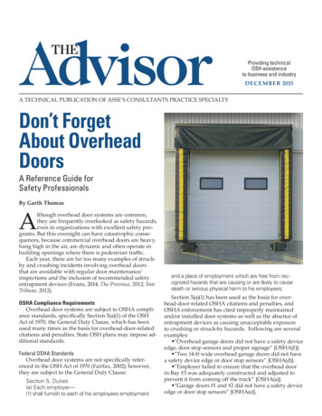
Section 4: Installation - HoistSectional Doors - Direct Couple (Right hand unit shown)HP1/2, 11/2, 13REQUIRED MOUNTING KITDIRECT COUPLE - 26RPMDIRECT COUPLE - 14RPMDIRECT COUPLE - 14RPMPART NUMBEROPMKDC26HX.SOPMKDC14HX.SOPMKDC14HX3HP.SThe RHX Hoist Operators are factory assembled for right-handmounting (shown). Each model can also be converted to lefthand mount See page 4.7 for instructions.NOTES:1) A clearance of 8” should be allowed for access to all electric connections.2) Average door travel speed varies per drum used.3) Operator mounting brackets mount to wall.Refer to Direct Couple Supplemental Instruction ( Included with Direct Couple Kit)SIDEMOUNT 14 RPM DIRECT COUPLESIDEMOUNT 26 RPM DIRECT COUPLEFigure 84.5
Section 4: Installation - HoistSectional Doors - Center Mount Direct Couple (Right hand unit shown)HP1/2, 11/2, 133REQUIRED MOUNTING KITCENTER MOUNT VERTICALCENTER MOUNT HORIZONTALCENTER MOUNT VERTICALCENTER MOUNT HORIZONTALPART X3HP.SHP1/2, 11/2, 13REQUIRED MOUNTING KITDIRECT COUPLE - 26RPMDIRECT COUPLE - 14RPMDIRECT COUPLE - 14RPMPART NUMBEROPMKDC26HX.SOPMKDC14HX.SOPMKDC14HX3HP.SThe RHX Hoist Operators are factory assembled for right-handmounting (shown). Each model can also be converted to lefthand mount See page 4.7 for instructions.NOTES:1) A clearance of 8” should be allowed for access to all electricconnections.2) Average door travel speed varies per drum used.3) Operator mounting brackets mount to wall.Refer to Direct Couple Supplemental Instruction, ( Included with D
Overhead Doors are large, heavy objects that move with the help of springs under high tension and electric motors. Since moving objects, springs under tension, and electric motors can cause . For the number of your local Overhead Door Dealer, call 800-929-3667, and for Overhead Door Factory Technical Advice, call 800-275-6187.