Transcription
FIRED HEATER DESIGNThis case study demonstrates the implementation of an API 560 fired heatercompound component in Flownex. It also shows how Flownex has been usedduring the process design and preliminary sizing of a typical API 560 firedheater, combustion air fan and the associated ducting. Results are comparedwith other commercial software.OIL AND GAS INDUSTRY
OIL AND GAS INDUSTRYChallenge:The main challenge in this cases study is the application of Flownex to: design the process by performing a heat and mass balance,size the fired heater and determine typical tube wall and flue gas temperatures,size the combustion air fan,determine the required ducting and piping sizes, and,analyze the combustion process, specifically the flue gas emissions.Benefits:By creating a fired heater compound component, a Flownex model can be developed which isable to model both the fluid flow, combustion and heat transfer processes. This combinedcapability is not commonly available in other design tools.Solution:Page1Flownex could effectively be used during the design and sizing of the fired heater, combustion airfan and the associated ducting.“To remain competitive in a globalised competitive environment,engineering companies have to perform the same tasks in a quicker,more efficient manner – they have to work smarter, not harder. In thecase of sizing packages such as a fired heater during the quotation stagewhen there is never enough time, Flownex has proven to be aninvaluable tool. It allows us to complete a very comprehensive sizinganalysis within a few hours. I am not aware of any other tool that can dothis to the level of detail done in this case study.”Hannes van der WaltPrincipal co Pty Ltd
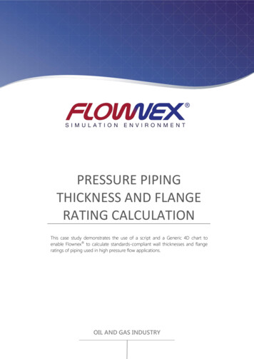
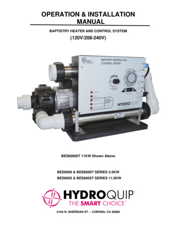
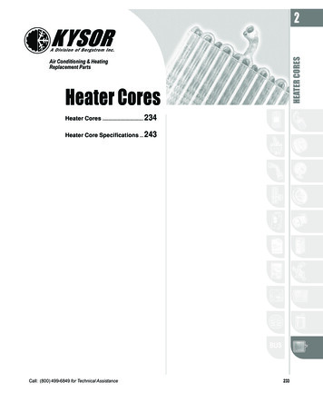
FIRED HEATER DESIGNIntroductionThe design of a fired heater (or similar) package typically starts with aheat and mass balance. This first step is necessary to determine theprocess parameters which determine most of the sizing of thepackage. A fired heater package heat and mass balance includes themodelling of the combustion process and the modelling of the heattransfer and fluid flow processes. Modelling the combustion processtypically involves the specification of the fuel gas composition, thecombustion air composition, the air-fuel ratio and the fuel flow rate.The heat transfer from the fired heater combustion process into theprocess fluid may be specified in terms of an overall heater thermalefficiency. Typical heat and mass balance calculations do not provideestimations of the physical size of the heater or even the ducting andother components such as combustion air fans, neither do they enablethe calculation of system pressure losses or heat losses. They are alsoincapable of providing insight into tube wall and process fluid filmtemperatures which are very important in the oil and gas industry.Flownex enables the user to perform all these tasks easily and quicklyin a single calculation.“Typical heat andmass balancecalculations do notprovide estimates ofthe physical size of theheater or even theducting and othercomponents such ascombustion air fans.Neither do theyenable the calculationof system pressure orheat losses. Flownex enables the user toperform all these taskseasily and quickly in asingle calculation.”ModelThe main purpose of this exercise is to size a fired heater (typically anAPI 560 design) and its associated combustion air fan and ducting. Inorder to perform this task efficiently, a Flownex model has beendeveloped which is able to model the combustion, fluid flow and heattransfer processes. As such the model relies on a fired heatercompound component and a few scripts to handle fuel and flue gasanalyses. Required data inputs are indicated by blue rectangles in Figure 1. The fired heatercompound component input and result fields are shown in Figure 2 and Figure 3 respectively.Page2Typically, the client would specify the following heater requirements: The required heater duty (to the process fluid).Process fluid composition and flow rate.Process fluid required inlet and outlet temperatures.A required, or at least a desired heater efficiency.Maximum allowable flue gas temperatures (if specified).Maximum allowable tube wall temperatures and/or process fluid film temperatures.Allowable process coil API erosional velocities, mass velocities or ρV2-values.Process coil fouling factors.Fuel gas composition.Ambient conditions.www.flownex.comsales@flownex.com
The required heater data specification is as follows: Page3 Estimate the heater efficiency based on previous experience, or if the efficiency is stated by theclient, specify this as the Required Efficiency (HHV). Typical fired heater HHV efficiencies rangefrom 75% to 80%.Add estimates for the Heater Flue Pressure Drop and Process Pressure Drop. A typical flue sidepressure drop is 50 kPa to 60 kPa. The model may be used to estimate the process sidepressure drop by specifying the expected number of return bends in the coils and a returnbend loss coefficient. These may be updated at a later stage when the actual heater pressuredrop has been determined via dedicated heater design software.Specify the heater configuration; Counter Flow or Parallel Flow. Most fired heaters are counterflow. In parallel flow designs the process fluid inlet would be at the radiant section and theoutlet at the top of the convection section. They are typically used in situations where corrosionmay be a problem at the top-most convection tubes. This occurs when the top convectiontube temperatures would be too close to the water or SOx acid gas dew point temperatures incounter flow configuration and therefore a risk of tube corrosion exists.Specify the Design Heat Flux. Adjust the Design Heat Flux to obtain larger or smaller coil areas.This parameter may also be used to obtain comfortable tube wall temperatures. This value mayrely on previous experience and also depends on the type of process fluid. For fluids wherelocal hot spots may cause degradation, such as oils, this value would be lower than others,such as air, where no such degradation occurs. From practical experience, the following areapproximate guidelines:o For water heating, a maximum of 36 kW/m2 should be used.o For oils with temperatures below 150 C, a maximum flux of 23 kW/m2 isrecommended.o For oils with temperatures between 150 C and 250 C, a maximum flux of 21 kW/m2 isrecommended.o For oils with temperatures above 250 C, a maximum flux of 19 kW/m2 isrecommended.o For natural gases and other gases such as air the heat flux may be set higher, howevera safe margin between the calculated tube wall temperature and the maximum designtemperature for the project at hand should exist.Since this model does not perform detailed radiation or even convection calculations, butsimply applies average heat fluxes over a coil area, peak fluxes and temperatures cannot becalculated. However, a Peak Heat Flux Factor is used to artificially increase the maximumtemperature values to obtain an estimate of potential maximum tube wall temperatures.Therefore, a minimum value of 1 causes no peak temperatures. From experience, peak walltemperatures are about 5% to 10% higher than averaged maximum temperatures.If the heater is to feature both a radiant section as well as a convection section, such as API 560Type C or Type E heaters, an estimate for the duty split between the radiant and convectionsections is specified. This is achieved by specifying the Radiant Duty Fraction. This value is alsoused to control the Radiant Chamber Exit Temperature which cannot be too high, else theconvection section will experience excessive temperatures, especially the tube fins. Typicalbridge wall temperatures of 1000 C or lower should be obtained. From practical experience,radiant sections transfer between 50% and 60% of the heat. Therefore start the first iterationwith a radiant duty fraction of 55%.The radiant section is sized based on the burner (or burners) flame size and layout. The flamedimensions are specified in terms of a Flame Length and a Flame Diameter for a single burner.Burner flame dimensions are available from the burner manufacturer for a specific duty rating.www.flownex.comsales@flownex.com
When multiple burners are used, the burners are arranged around a Burner Circle of which theDiameter must be specified. This diameter is zero for a single burner. Furthermore, a clearancemust exist between the flame edge and the coil wall. These are typically 0.4m to 0.6m. Theseparameters will be used to determine the radiant section coil PCD.To estimate the required radiant section height, a Radiant Chamber Height to Width Ratio isspecified. API 560 recommends a maximum value of 2.75 and a minimum of 1.5. Forhorizontally oriented heaters, API 560 recommends a range of H/W ratios for both maximaand minima depending on the heater duty. A ratio of 2.5 may be a good starting value.Another related factor specified by API 560 is a maximum volumetric heat release of 165kW/m3 for gas fired heaters. Ensure that this limit is not exceeded with the selected geometry.The process fluid is selected as well as the coil materials.Coil inside and outside fouling factors may be specified. Fouling factors have a significantinfluence on tube wall temperatures.The coil geometry is specified in terms of the diameter, thickness and the number of parallelflow paths which essentially “duplicates” the coil into parallel flowing coils. Start by specifying acoil size and number of parallel flow paths that feels right from experience. After the firstsolution is obtained, the coil size and/or number of parallel flow paths may be adjusteddepending on velocity and pressure drop considerations.Lastly, in the case of a convection section being present, a fin geometry may be specified. Themodel does not have the functionality to specify shock tubes - bare tubes without fins, usuallythe first 3 rows in the convection section. Since the model simply determines the required baretube area from the specified Design Heat Flux, the specification of fins has no influence on thecalculated required convection coil length. The only purpose of specifying the fin geometry isfor the model to estimate likely fin tip temperatures and to calculate an equivalent averageconvection coefficient which only serves as a reality check. Typical convection coefficients rangebetween 10 and 30 W/m2.K. According to API 560, fin lengths should not exceed 25.4mm andthe minimum fin thickness is recommended to be 1.3mm. From practical experience, finlengths may include 10mm, 12.5mm, 20mm and 25.4mm whilst the fin thickness may be either1.3mm or 1.5mm. Fin densities should remain below approximately 200 fins/m according toAPI 560.The heater, combustion air fan and ducting are then sized by following the steps below: Page4 Having specified a required or desired heater thermal efficiency, adjust the Fuel Gas Flow Rateto obtain the required Heat to Process (Duty) to achieve the required process fluid outlettemperature.Adjust the Excess Air % (Wet) to obtain the required Adiabatic Flame Temperature (theoreticalmaximum combustion temperature) and therefore indirectly the Flue Temperature into theconvection section and into the stack. These temperatures depend on the combination of fuelflow rate, excess air percentage and the heater efficiency. Furthermore, the excess air alsodirectly influences the O2 and CO concentrations in the flue gas. API 560 recommends 15%excess air for forced draft heaters and 20% excess air for natural draft heaters.Adjust the Radiant Duty Fraction if required, however this is a major unknown as the modeldoes not really perform any radiation heat transfer calculations. Therefore aim to use the valuessuggested above.Adjust the coil geometry to satisfy velocity, mass velocity or ρV2-value requirements. Both thecoil diameter and the number of parallel coils may be altered to achieve desired flow velocities.From practical experience, aim for velocities between 3 m/s and 4 m/s for liquids such as water.For more viscous liquids, the velocities may be significantly lower and the pressure drop maywww.flownex.comsales@flownex.com
be the governing factor. For gases, aim for velocities of approximately 15 m/s.Adjust the Design Heat Flux. Again, when the process fluid is temperature sensitive, aim to usethe values suggested above.Inspect the velocities in the air, fuel and flue piping and ducting and adjust their sizes to obtaincomfortable velocities.The combustion air fan flow rate is automatically set by the required combustion air flow ratecalculated in the combustion calculations. The fan element then calculates the required dutypoint to satisfy the flow and pressure requirements.SOLUTIONThe model calculates the following: Page5 The combustion system performance. These include:o The calculated heat to process to achieve the required process fluid temperatureincrease;o Required burner heat release (HHV and LHV);o The heater thermal efficiency (HHV and LHV);o Combustion temperature;o Radiant chamber flue gas exit temperature;The heater geometry as follows:o The required coil lengths for both the radiant and convection sections;o The required coil areas for both the radiant and convection sections;o The radiant section chamber PCD and height;The flue gas flow results:o Flue gas mass flow and average actual volume flow;o Flue gas average density;o Flue gas side pressure drop;The process fluid results:o Process fluid mass flow;o Process fluid inlet and outlet temperatures for both the radiant and convectionsections;o Process fluid inlet pressure and pressure drop;o Process fluid inlet and outlet velocities for both the radiant and convection coils;o API 14E erosional velocity, the mass velocity and the ρV2-value for both the radiantand convection coilsThe heat transfer results:o Heat transfer to each coil;o Average heat flux to each coil;o Radiant section volumetric heat release;o Convection section average convection coefficient;o Convection section estimated maximum fin tip temperature;o Coil inside and outside surface temperatures (minimum, maximum and average).the required fuel flow rate;the required air flow rate;The required combustion fan pressure rise and flow rate;Pressure drops for the various components;Duct and pipe velocities – check for duct and pipe sizing;www.flownex.comsales@flownex.com
Flue gas properties; of particular interest may be the oxygen content, the CO content, the SO2content and the dew point temperatures.CASE STUDYAs an example, a natural gas fired heater package is to be designed to heat 73.6 kg/s of waterflow from 155 C to 175 C. Perform a quick 15 minute heater package sizing and compare theresults with a detailed final heater design done on a third-party fired-heater software such as HTRIor FRNC.Data SpecificationTypical fired heater properties when heating water are approximately as follows:General DataPropertyUnitValueThermal efficiency (HHV)Thermal efficiency (LHV)Flue side pressure dropProcess side pressure dropDesign Heat FluxPeak Heat Flux FactorRadiant chamber duty fractionFouling (outside)Maximum flue velocityMaximum water velocityMaximum tube wall temperatureMaximum fin temperatureBurner CircleFlame-to-Wall ClearanceRadiant Chamber Height-to-WidthFin HeightFin ThicknessFin DensityBurner DataManufacturerModelFuel Supply PressureAir Supply PressureMax. Flame LengthMax Flame Diameter%%PakPakW/m2%%m2.K.Wm/sm/s C 552.75201.5160Page6Fives North omsales@flownex.com
RESULTS COMPARISON & DISCUSSIONPage7The following results were obtained using the Flownex model and are compared to resultsobtained from an actual detailed design done using HTRI:www.flownex.comsales@flownex.com
Unit%%kWFlownex8088.26401HTRI89.96510Heat release (HHV)Heat release (LHV)Fuel gas flow ratekWkWkg/hr800172595467211536Combustion air flow rateFlue gas flow rateAdiabatic flame temperatureRadiant chamber duty fractionRadiant chamber exit temperatureStack flue gas exit temperatureStack flue gas water dew point temperatureStack flue gas SOx acid dew point temperatureStack flue gas O2 contentFlue side pressure dropProcess side pressure dropDesign Heat FluxRadiant coil average heat fluxConvection coil average heat fluxConvection coil average convection coefficientRequired radiant coil lengthRequired convection coil lengthMaximum flue velocity in ductingMaximum water velocityAPI 14E erosional velocityMass velocitykg/hrkg/hr C% C C C 11.63.76.13331104521098855.9972224Note 13.02625326.829.620.1367Note 2270Note 23.7-ρV2Pa12347-Maximum radiant section tube wall temperatureAverage radiant section tube wall temperatureMaximum convection section tube wall temperatureAverage convection section tube wall temperatureMaximum fin temperatureConvection section process inlet temperatureCrossover process temperatureRadiant section outlet process temperatureCombustion air fan required pressure rise C C C C C C C -Combustion air fan required hydraulic dutykW28.5-Page8PropertyThermal efficiency (HHV)Thermal efficiency (LHV)Heat to Processwww.flownex.comsales@flownex.com
Note 1: Due to the higher efficiency of the final design using HTRI, the HTRI calculated stack flue gastemperature is slightly lower. Changing the Flownex required efficiency to align with the HTRI results, a fluegas temperature within 10 C of the HTRI result is obtained.Page9Note 2: Note that the heater geometry was first determined using Flownex, and the HTRI modelsubsequently used this geometry.Figure 1: Flownex Model.www.flownex.comsales@flownex.com
10PageFigure 2: Fired Heater Inputs.www.flownex.comsales@flownex.comFigure 3: Fired Heater Results.
SummaryUsing Flownex , the design and sizing of the fired heater, combustion air fan and the associatedpiping and ducting could be performed within an hour. Furthermore, results such as processtemperatures, tube wall temperatures, heat fluxes, flow velocities, pressure losses etc. could easilybe obtained from the network. As an overall package sizing and design tool, Flownex has provento be far more efficient than other detailed design software.Case Study Flownex Model AvailabilityThe Flownex model discussed in this case study is available in the user project downloads arealocated flownex.comsales@flownex.com
Coil inside and outside fouling factors may be specified. Fouling factors have a significant influence on tube wall temperatures. The coil geometry is specified in terms of the diameter, thickness and the number of parallel flow paths which essentially "duplicates" the coil into parallel flowing coils. Start by specifying a