Transcription
FE: Electric Circuits C.A. GrossEE1-1FUNDAMENTALS OF ENGINEERING(FE) EXAMINATION REVIEWELECTRICALENGINEERINGCharles A. Gross, Professor EmeritusElectrical and Comp EngineeringAuburn University Broun hnology.comFE: Electric Circuits C.A. GrossEE1-21
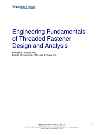
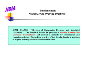
EE Review Problems1.2.3.4.dc CircuitsComplex Numbersac Circuits3-phase Circuits1st Order TransientsControlSignal ProcessingElectronicsDigital SystemsFE: Electric CircuitsWe will discussthese.We may discussthese as timepermits C.A. GrossEE1-3EE1-41. dc Circuits:Find all voltages, currents, and powers.FE: Electric Circuits C.A. Gross2
SolutionThe 8 and 7 resistors are in series:R1 8 7 15 R1 and 10 are in parallel:1R2 11 10 R110 R1 6 10 R1FE: Electric Circuits C.A. GrossEE1-5EE1-6Solution4 and R2 are in series:Rab 4 R 2 10 L :Ia Vab 100 10 ARab 10V4 4 I a 40V( L)V10 100 40 60VFE: Electric Circuits KVL C.A. Gross3
SolutionIc V10 60 6A10 10 L KCL :I b I a I c 10 6 4 AV8 8 I b 32V( L)V7 7 I b 28V( L)FE: Electric Circuits C.A. GrossEE1-7Absorbed Powers.R4 I a2 4 10 400W2R10 I 10 6 360WR7 I b2 7 4 112W2R8 I 8 4 128W2bIn General:22cPABS PDEV(Tellegen's2Total Absorbed Power 1000WTheorem)Power Delivered by Source Vs I a 100 10 1000WFE: Electric Circuits C.A. GrossEE1-84
2. Complex NumbersConsiderx2 2 x 5 02 ( 2) 2 4(1)(5) 2 16 x 2 124 1 1 1 2 12The numbers "1 2 1" are called complex numbers9Summer 2008The “I” (j) operatorMath Department.ECE DepartmentDefine i 1Define j 1x 1 j2x 1 2iWe choose ECE notation! Terminology Rectangular Form.Z X jY a complex numberX e Z real part of ZY Im Z imaginary part of Z10Summer 20085
Polar FormMath Department.Z R e i a complex numberR Z modulus of Z arg Z argument of Z radians ECE Department.Z Z a complex numberZ Z magnitude of Z ang Z angle of Z degrees 11The Argand DiagramIt is useful to plot complex numbers in a 2-D cartesianspace, creating the so-called Argand Diagram (JeanArgand (1768-1822)).“imaginary” axis (Y) 2Z X jY 1 j 2“real” axis (X) 112Summer 20086
ConversionsRetangular PolarZ YX2 Y2 Y X tan 1 Z Polar Retangular.X Z cos XY Z sin 13Summer 2008Example:Z 3 j4X e Z 34Y Im Z 4Rect Polar.5 0Z 32 42 53 4 Summer 2008 tan 1 0.9273 rad 53.103147
ConjugateZ X jY Z Z * conjugate of Z X jY Z Example.(3 j 4)* 3 j 4 5 53.1015Summer 2008Addition (think rectangular)A a jb A 3 j 4 5 53.10B c jd B 5 j12 13 67.40A B (a jb) (c jd ) (a c ) j (b d )A B (3 j 4) (5 j12) (3 5) j (4 12) 8 j816Summer 20088
Multiplication (think polar)A a jb A 3 j 4 5 53.10B c jd B 5 j12 13 67.40A B ( A ) ( B ) A B ( )A B (5 53.10 ) (13 67.40 ) (5) (13) (53.10 67.40 ) 65 14.3017Summer 2008Division (think polar)A a jb A 3 j 4 5 53.10B c jd B 5 j12 13 67.40A A A ( )B B B A 5 53.10 5 53.10 67.40 0 B 13 63.4 13 0.3846 120.5018Summer 20089
Multiplication (rectangular)A B (a jb) c jd ac bd j ad bc A B (3 j 4) (5 j12) (15 48) j ( 36 20) 63 j16 65 14.3019Summer 2008ELEC3810Addition (polar)5 53.10Complex numberaddition is thesame as "vectoraddition"!20Summer 200811.31 450EL13 67.40EC381010
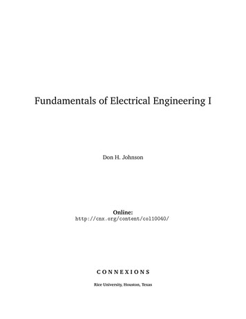
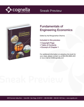
3. ac Circuitsi(t)Find "everything"in the givencircuit.8 v(t)-0.663 mF26.53 mHv (t ) 141.4cos(377 t ) VFE: Electric Circuits C.A. GrossEE1- 21Frequency, periodv (t ) 141.4cos(377 t ) V(radian) frequency 377 rad / s(cyclic) frequency f Period FE: Electric Circuits 60 Hz2 11 16.67 msf 60 C.A. GrossEE1- 2211
The ac CircuitTo solve the problem, we convert the circuitinto an "ac circuit":R, L, C elements Z (impedance)v , i sources V , I (phasors)R : Z R R j0 8 j0L : Z L 0 j L 0 j (0.377)(26.53) 0 j10C : ZC 0 11 0 j 0 j40.377(0.663)j CFE: Electric Circuits C.A. GrossEE1- 23The Phasorv (t ) VMAX cos( t )To convert to a phasor.For example.V FE: Electric CircuitsV VMAX2 v (t ) 141.4cos(377 t )VMAX2 100 0o C.A. GrossEE1- 2412
The "ac circuit"I L(ac ) : VR 100 0 I VC FE: Electric Circuits1008 j10 j 4 10 36.9o VLVZi (t ) 14.14 cos(377 t 36.9o ) C.A. GrossEE1- 25Solving for voltagesVR Z R I (8)(10 36.9o ) 80 36.9o Vv R (t ) 113.1 cos(377 t 36.9o )VC Z C I ( j 4)(10 36.9o ) 40 126.9o VvC (t ) 56.57 cos(377t 126.9o )VL Z L I ( j10)(10 36.9o ) 100 53.1o Vv L (t ) 141.4 cos(377 t 53.1o )FE: Electric Circuits C.A. GrossEE1- 2613
Absorbed powersS V I * P jQS R VR I * 80 36.9o (10 36.9o )* 800 j 0SC VC I * 40 126.9o (10 36.9o )* 0 j 400S L VL I * 100 53.1o (10 36.9o )* 0 j1000STOT S R SC S L 800 j 600PTOT 800 watts;QTOT 600 var s;STOT STOT 1000 VAFE: Electric Circuits C.A. GrossEE1- 27Delivered powerS S VS I * 100 0o (10 36.9o )* 800 j 600S S STOT 800 j 600PS PTOT 800 wattsQS QTOT 600 var sIn General: PABS PDEVQABS QDEV(Tellegen's Theorem)FE: Electric Circuits C.A. GrossEE1- 2814
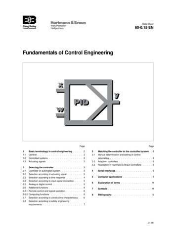
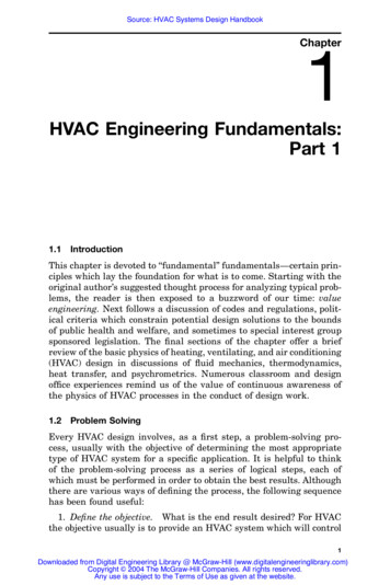
The Power Triangle S 800 j 600S 1000 VAQ 600 var 36.90V 100 0oI 10 36.9oP 800 Wpower factor pf FE: Electric CircuitsP cos( ) 0.8 laggingS C.A. GrossEE1- 29Leading, Lagging ConceptsLeading CaseIQ 0VLagging CaseVQ 0IFE: Electric Circuits C.A. GrossEE1- 3015
A Lagging pf Example V 7.2 00 kV jXRjX j 43.2 R 103.68 FE: Electric Circuits C.A. GrossEE1- 31Currents IVIRV RIR IL ILjXV7.2 69.44 AR 103.68I IR ILV7.2 j166.7 AjX j 43.20FE: Electric CircuitsI 69.44 j166.7I 180.6 67.380 A C.A. GrossEE1- 3216
pf cos cos 67.360 0.3845Powers IILIRV R1300 kVAjX1200 k varS R V I R * 500 kW j 0S L V I L * 0 j1200 k varSS V I * S R S L500 kWSS 500 j1200 1300 67.380FE: Electric CircuitsEE1- 33 C.A. GrossAdd CapacitanceII C j125 jX CVIR IC ILICI R 69.44V7.2 j125 A jX j 57.6I L j166.7I I R I L ICI 69.44 j166.7 j125 81 310 AFE: Electric Circuits C.A. GrossEE1- 3417
Powerspf cos cos 310 0.8575 900 kvar1200 kvarSC V I C * 0 j 900 kvar583.1 kVASS V I * S R S L SCSS 500 j1200 j 900500 kWSS 583.1 310 kVAFE: Electric Circuits C.A. GrossEE1- 35ObservationsBy adding capacitance to a lagging pf (inductive) load, wehave significantly reduced the source current., withoutchanging P!BeforeI 180.6 A;pf 0.3845I 81 A;pf 0.8575AfterNote that:low pf, high current;high pf, low current;If we consider the “source” in the example to represent anElectric Utility, this reduction in current is of major practicalimportance, since the utility losses are proportional to thesquare of the current.FE: Electric Circuits C.A. GrossEE1- 3618
ObservationsThat is, by adding capacitance the utility losses havebeen reduced by almost a factor of 5! Since this resultsin significant savings to the utility, it has an incentive toinduce its customers to operate at high pf.This leads to the “Power Factor Correction” problem, whichis a classic in electric power engineering and is extremelylikely to be on the FE exam.We will be using the same numerical data as we did in the previous example.Pretty clever, eh’ what?FE: Electric CircuitsEE1- 37 C.A. GrossThe Power Factor Correction problemUtilityLoadpf correctingcapacitanceAn Electric Utility supplies 7.2 kV to a customer whose loadis 7.2 kV 1300 kVA @ pf 0.3845 lagging. The utility offersthe customer a reduced rate if he will “correct” (“improve”or “raise”) his pf to 0.8575. Determine the requisitecapacitance.FE: Electric Circuits C.A. GrossEE1- 3819
PF Correction: the solution1. Draw the load power triangle.1300 kVA @ pf 0.3845 lagging.pf 0.3845 cos 67.380S LOAD S 1300 67.381200 kvar0S LOAD 500 j1200Because the pf is lagging, the load isinductive, and Q is positive. Therefore wemust add negative Q to reduce the total,which means we must add capacitance.67.380500 kWFE: Electric Circuits C.A. GrossEE1- 39PF Correction: the solution2. We need to modify the source complex power sothat the pf rises to 0.8575 lagging.pf 0.8575 cos 310Closing the switch (inserting the capacitors)SS 500 j1200 jQC 500 j 1200 QC Let QX 1200 QCTherefore SS 500 jQX S S 310 kVAThen Tan FE: Electric CircuitsQX Tan 310 0.6500 C.A. GrossEE1- 4020
PF Correction: the solutionQX 0.6500QX 300 kvarQC 1200 Q X 900 kvar900 kvarThe new source power triangle1200 kvarInstall 900 kvar of7.2 kV Capacitors300 kvar500 kWFE: Electric Circuits C.A. GrossEE1- 414. Three-phase ac CircuitsAlthough essentially all types of EE’s use ac circuit analysisto some degree, the overwhelming majority of applicationsare in the high energy (“power”) field.It happens that if power levels are above about 10 kW, it ismore practical and efficient to arrange ac circuits in a“polyphase” configuration. Although any number of“phases” are possible, “3-phase” is almost exclusively usedin high power applications, since it is the simplest case thatachieves most of the advantage of polyphase.It is virtually certain that some 3-phase problems will appearon the FE and PE examinations, which is why 3-phasemerits our attention.21
A single-phase ac circuita nGeneratorLineLoad“a” is the “phase” conductor“n” is the “neutral” conductorFor a given load, the phase a conductor must have a crosssectional area “A”, large enough to carry the requisitecurrent. Since the neutral carries the return current, we needa total of “2A worth” of conductors.Tripling the capacity IaIbIcInIf I a I b I c I then I n 3I We need a total of A A A 3A 6A conductors.22
But what if the currents are not in phase?Suppose I a I 00 I b I 1200 I c I 1200ThenI n I a I b I c I 00 I 1200 I 1200I n I 1 j0 0.5 j 0.866 0.5 j0.866 I n I 1.0 0.5 0.5) j(0.0 0.866 0.866 I (0 j 0) 0Now we only need a total of A A A 0 3A conductors!A 50% savings!The 3-Phase SituationFE: Electric Circuits C.A. GrossEE1- 4623
"Balanced" voltage means equal inmagnitude, 120o separated in phasev an ( t ) V max cos( t ) 2 V cos( t )vbn ( t ) V max cos( t 120 0 ) 2 V cos( t 120 0 )vcn ( t ) V max cos( t 120 0 ) 2 V cos( t 120 0 )Van V 00Vbn V 1200Vcn V 1200FE: Electric Circuits C.A. GrossEE1- 47The “Line” VoltagesBy KVL Vab Van Vbn 13 0Vab V 00 V 1200 V 1 j 0 j V 3 3022 Vbc V 3 900Vca V 3 1500Vab Vbc Vca VL V 3FE: Electric Circuits C.A. GrossEE1- 4824
When a power engineer says “theprimary distribution voltage is 12 kV”he/she means An ExampleVab 12.47 300 kVVbc 12.47 900 kVVab Vbc Vca VL 12.47 kVVca 12.47 1500 kVVan Vbn Vcn Van 7.2 00 kVVL 7.2 kV3FE: Electric CircuitsVbn 7.2 1200 kVVcn 7.2 1200 kV C.A. GrossbcEE1- 49An Important Insight .All balanced three-phase problems can besolved by focusing on a-phase, solving thesingle-phase (a-n) problem, and using 3-phasesymmetry to deal with b-n and c-n values!This involves judicious use ofthe factors 3, 3, and 1200!To demonstrate FE: Electric Circuits C.A. GrossbcEE1- 5025
Recall the pf Correction ProblemAn Electric Utility supplies 7.2 kV to a single-phase customerwhose load is 7.2 kV 1300 kVA @ pf 0.3845 lagging. V 7.2 00 kV 104 j 43.2 1300 kVA1200 kvarI I R I L 181 67 A0FE: Electric Circuits C.A. Gross500 kWbcEE1- 51The pf Correction Problem in the 3-phase caseAn Electric Utility supplies 12.47 kV to a 3-phase customerwhose load is 12.47 kV 3900 kVA @ pf 0.3845 lagging. Van 7.2 00 kV104 j 43.2 3900 kVA3600 kvarI a 181 670 A3 times bigger!1500 kWFE: Electric Circuits C.A. Gross52EE1-26
If we want all the V’s, I’s, and S’sVan 7.2 00 kVVab 12.47 300 kVVbn 7.2 1200 kVVbc 12.47 900 kVVcn 7.2 1200 kVVca 12.47 1500 kVI a 181 670 ASa 500 j1200 kVAI b 181 187 ASb 500 j1200 kVAI c 181 53 ASc 500 j1200 kVA00FE: Electric Circuits C.A. GrossEE1-PF Correction: the 3ph solutionInstall 2700 kvar ofCapacitance.2700 kvar3600 kvarThe circuitry in the 3phase case is a bitmore complicated.There are twopossibilities .900 kvar1500 kWFE: Electric Circuits C.A. GrossEE1- 5427
The wye connection .SOURCEaLOADbcnInstall three 900 kvar7.2 kV wye-connectedCapacitors.FE: Electric Circuits C.A. GrossEE1- 55The delta connection .SOURCEaLOADbcnInstall three 900 kvar 12.47 kV delta-connectedCapacitors.FE: Electric Circuits C.A. GrossEE1- 5628
Z 3 ZYwye-delta connectionswye case2700Qan 900 kvar3Ia delta caseQan Qan 900 125 AVan 7.2Zan ZY CY Iab Van 57.6 Ia2700 900 kvar3Qab 900 72.17 AVab 12.47Zab Z 1 46.05 F ZYC FE: Electric Circuits12.47 172.8 72.171 15.35 F Z C.A. GrossEE1- 571st Order Transients .i t Network BNetwork A containsdc sources,resistors,one switchv t containsone energystorageelement(L or C)The problem .(1) solve for v and/or i @ t 0; (2) switch isswitched @ t 0; (3) solve for v and/or i for t 0FE: Electric Circuits C.A. GrossEE1- 5829
The inductive casevL L di LdtL's are SHORTS to dciL(t) cannot change in zero timei L (0 ) i L (0) i L (0 )FE: Electric Circuits C.A. GrossEE1- 59An Example vL L di LdtFE: Electric Cir
FE: Electric Circuits C.A. Gross EE1-1 FE: Electric Circuits C.A. Gross EE1-2 FUNDAMENTALS OF ENGINEERING (FE) EXAMINATION REVIEW www.railway-technology.com