Transcription
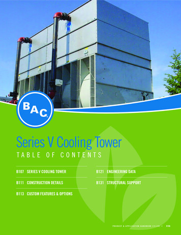
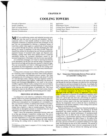
VXT - B 1VXTOpen Cooling TowersOpen Cooling TowersProduct DetailEngineering Data . B2Structural Support . B6Engineering Specifications . B9
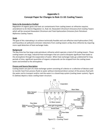
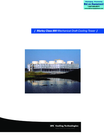
VXT - B 2Engineering DataREMARK: Do not use for construction. Refer to factory certified dimensions & weights. This brochure includes datacurrent at time of publication, which should be reconfirmed at the time of purchase. In the interest of productimprovement, specifications, weights and dimensions are subject to change without notice. More can be found atwww.BaltimoreAircoil.com.VXTVXT 10 - 1851. Drain ND 50; 2. Water Outlet; 3. Overflow ND50 (Overflow VXT 150 – 185: ND80); 4. Make Up ND25; 5.Water Inlet; 6.Access Door.On models VXT-10 to VXT-135 sufficient space must be provided on the back of the unit for entry to access doors located on side opposite airentry side.ModelVXTOperating m)L(mm)W(mm)Air Flow(m3/s)Fan Motor Fluid Inlet Fluid Outlet Make Up(kW)ND (mm)ND (mm) ND (mm)VXT 010VXT 015VXT 020VXT ,50(1x) 0,75(1x) 1,1(1x) 1,5(1x) 2,2(1x) 80(1x) 80(1x) 80(1x) 80(1x) 80(1x) 80(1x) 80(1x) 8025252525VXT 030VXT 040VXT 045VXT 975,16(1x) 1,5(1x) 2,2(1x) 4,0(1x) 5,5(1x) 80(1x) 80(1x) 80(1x) 80(1x) 80(1x) 80(1x) 80(1x) 8025252525VXT 065VXT 070VXT 075VXT 28,028,83(1x) 5,5(1x) 5,5(1x) 5,5(1x) 7,5(1x) 100(1x) 100(1x) 100(1x) 100(1x) 100(1x) 100(1x) 100(1x) 10025252525VXT 095VXT 105VXT 120VXT 10,9012,5812,46(1x) 7,5(1x) 7,5(1x) 11(1x) 11(1x) 100(1x) 100(1x) 100(1x) 100(1x) 100(1x) 100(1x) 100(1x) 10025252525VXT 150VXT 165VXT 36453645364514381438143815,7915,5316,94(1x) 15(1x) 15(1x) 18,5(1x) 150(1x) 150(1x) 150(1x) 150(1x) 150(1x) 150252525* Units ship in one piece, ** Casing is heaviest sectionBaltimore Aircoil
VXT - B 3VXT N215 - eaviestSection(kg)VXT N215VXT N240VXT 2635503550355023972397239723,4923,3324,26(1x) 22(1x) 22(1x) 30(1x) 150(1x) 150(1x) 150(1x) 200(1x) 200(1x) 200505050VXT N310VXT N345VXT N370VXT 34,1233,8233,6036,15(1x) 30(1x) 30(1x) 30(1x) 37(1x) 200(1x) 200(1x) 200(1x) 200(1x) 200(1x) 200(1x) 200(1x) 20050505050VXT N430VXT N480VXT N510VXT 46,9846,6546,4448,94(2x) 22(2x) 22(2x) 22(2x) 30(2x) 150(2x) 150(2x) 150(2x) 150(1x) 250(1x) 250(1x) 250(1x) 25050505050HLWAir Flow Fan Motor Fluid Inlet Fluid Outlet Make Up(mm) (mm) (mm)(m3/s)(kW)ND (mm)ND (mm)ND (mm). because temperature mattersOpen Cooling Towers1. Drain ND 50; 2. Water Outlet; 3. Overflow ND 80; 4. Make Up ND50; 5.Water Inlet; 6.Access Door.
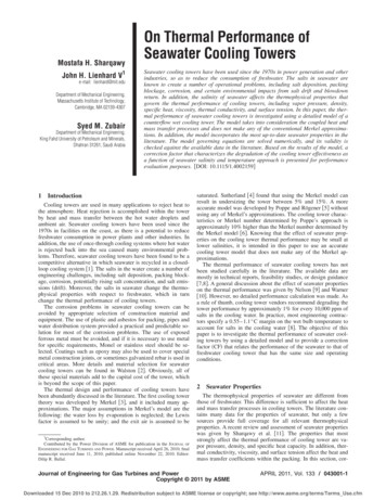
VXT - B 4VXTVXT 315 - 12001. Drain ND50; 2. Water Outlet; 3. Overflow ND 80; 4. Make Up ND50 and 870 - 1200: ND80; 5.Water Inlet; 6.Access HeaviestSection(kg)H(mm)L(mm)W(mm)VXT 315VXT 350VXT 375VXT 4,5534,3134,1036,62(1x) 30(1x) 30(1x) 30(1x) 37(1x) 200(1x) 200(1x) 200(1x) 200(1x) 200(1x) 200(1x) 200(1x) 20050505050VXT 470VXT 525VXT 560VXT 1,8251,4450,9254,93(2x) 22(2x) 22(2x) 22(2x) 30(1x) 250(1x) 250(1x) 250(1x) 250(1x) 250(1x) 250(1x) 250(1x) 25050505050VXT 630VXT 700VXT 750VXT 0069,0968,6268,2073,25(2x) 30(2x) 30(2x) 30(2x) 37(2x) 200(2x) 200(2x) 200(2x) 200(1x) 300(1x) 300(1x) 300(1x) 30050505050VXT 870VXT 945VXT 1050VXT 1125VXT ,93102,30109,87(3x) 22(3x) 30(3x) 30(3x) 30(3x) 37(3x) 200(3x) 200(3x) 200(3x) 200(3x) 200(2x) 250(2x) 250(2x) 250(2x) 250(2x) 2508080808080Air Flow Fan Motor Fluid Inlet Fluid Outlet Make Up(m3/s)(kW)ND (mm)ND (mm) ND (mm)General Notes1. All connections 100 mm and smaller are MPT. Connections 150mm and larger are bevelled-for-welding.2. Fan kW is at 0 Pa ESP. To operate against external static pressureup to 125 Pa, increase each fan motor one size.3. The drawings show the standard “right hand” arrangement, whichhas the air inlet side on the right when facing the connection end.“Left hand” arrangement can be furnished by special order.4. Water outlet, overflow and make-up are always located on thesame end of the unit. For units with two water outlet connectionsan additional overflow connection will be installed on the other endof the unit.Baltimore Aircoil
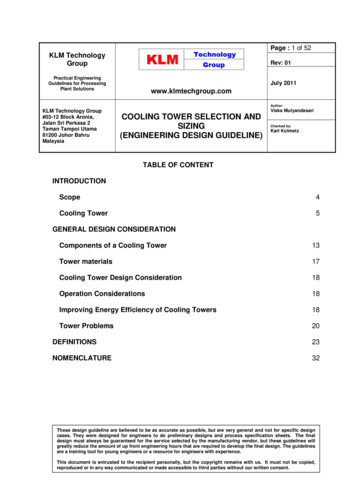
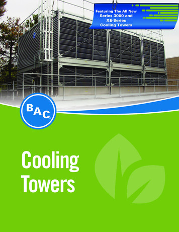
VXT - B 5Sound AttenuationXB Sound Attenuation for VX-Line Cooling TowersModel No.VXT# Accessdoors (3)Unit XBAtten. #piecesshipped Disch. eSolid DischaBottom rge Total10 - 253122352109010308909001303015031030 - 553(1)12235210901030180018152205022049065 - 853(1)12235210901030271027303007035072095 - 1354(2)1223521090103036353645370100420890150 - 185412258316001420363536454801205201120N215 – N265412354220701955351036456301906501470N310 – N395422354220701955536554808603009702130N430 - N5357223542207019557185732012603801300 2940315 - 40042241452560296535103645710230880470 - 600422414525602965536554809803501210 2540630 - 8007424145256029657185732014204601760 3640870 - 12001033414525602965 10865 10995 21306902640 5460(1)VXT-55 attenuation is shipped in 4 pieces(1)VXT-75 and VXT 85 attenuation is shipped in 4 pieces(2)VXT-95 attenuation is shipped in 3 pieces(3)Intake Attenuator: Access opening is 775 mm high, 406 mm wide and is located at each end of the unit.1820(3)Discharge Attenuator : Access opening is 400 mm high, 1080 mm wide and is located at blank off side of the unit (Access door of VXT 10-25has 650 mm width). because temperature mattersOpen Cooling Towers1. Access Door; L1 Intake Attenuator Length; L2 Discharge Attenuator Length; W & H unit dimensions (see Engineering Data).
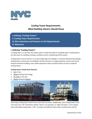
VXT - B 6Structural SupportREMARK: Do not use for construction. Refer to factory certified dimensions & weights. This brochure includes datacurrent at time of publication, which should be reconfirmed at the time of purchase. In the interest of productimprovement, specifications, weights and dimensions are subject to change without notice. More can be found atwww.BaltimoreAircoil.com.VXTThe recommended support arrangement for units consists of parallel I-beams running the full length of the unit, spaced as shown in the followingdrawing. Besides providing adequate support, the steel also serves to raise the unit above any solid foundation to ensure access to the bottomof the unit. To support units in an alternate steel support arrangement, consult your BAC Balticare Representative.Units without Sound Attenuation1. Outline of Unit; 2. Mounting Holes Ø 22 mm; 3. Unit; 4. Air Intake.AUnit Length(mm)BUnit Width(mm)CCenter dis.Length(mm)DCenter dis.Width(mm)E(mm)F(mm)G(mm)H(mm)XMax. Deflection(mm)MountingHolesVXT 10-2591412077501153----24VXT 30-551829120716641153----54VXT 65-842737120725721153----84VXT 95-1353658120734921153----104VXT 150-1853645143834921378----104VXT N215-N2653550239732382327----104VXT 315-4003550300032382934----104VXT N310-N39553882397507423272496102--138VXT 470-60053883000507429342496102--138VXT N430-N53572262397691423273238438--138VXT 630-80072263000691429343238438--138VXT altimore Aircoil
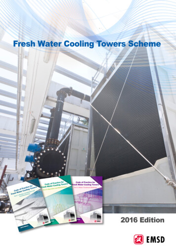
VXT - B 7Units with Sound AttenuationOpen Cooling Towers1. Outline of Unit; 2. Mounting Holes Ø 22 mm; 3. Outline of attenuator ; 4. Support Channel attached XB attenuator; 5. Unit; 6. SoundAttenuation; 7. Air Intake. because temperature matters
VXT - B 8Notes:1. The recommended support arrangement for VX units consists ofparallel I-beams extending the full length of the unit. Supports andanchor bolts are to be designed and furnished by others.VXT2. All supporting beams are to be flush and level at top and must beoriented relative to gage line as shown.3. Recommended design loads for each unit support beam shouldbe 70% of the total unit operating weight applied as a uniform loadto each of the unit beams. The support beam(s) for the optionalintake attenuator(s) needs to carry attenuator only, uniform load of250 kg/m. Beams should be designed in accordance withstandard structural practice. For the maximum allowabledeflection of beams under the unit refer to above table.4. All mounting holes have a diameter of 22 mm at the locationsshown.5. If vibration isolators are used, a rail or channel must be providedbetween the unit (and optional attenuator) and the isolators toprovide continuous unit support. Additionally the support beamsmust be designed to accommodate the overall length andmounting hole location of the isolators that may differ from thoseof the unit. Refer to vibration isolator drawings for these data.Baltimore Aircoil
VXT - B 9Engineering Specifications1.0 Cooling Tower1.1 General: Furnish and install factory-assembled, forceddraft, centrifugal fan, counter flow cooling tower(s) with vertical airdischarge, conforming in all aspects to the specifications, schedulesand as shown on the plans. Overall dimensions shall not exceedapproximately mm long x mm wide x mm high.The total connected fan power shall not exceed kW. Thecooling tower(s) shall be Baltimore Aircoil Model .1.3 Corrosion Resistant Construction (standard): Unlessotherwise noted in this specification, all steel panels and structuralmembers shall be constructed of heavy-gauge Z600 metric hot-dipgalvanized steel with all edges given a protective coating of zinc-richcompound and the exterior protected with the BALTIPLUS Protection.(Alternate 1.3) Corrosion Resistant Construction (optional):Unless otherwise noted in this specification, all steel panels andstructural members shall be protected with the BALTIBOND (Alternate 1.3) Corrosion Resistant Construction (optional):Unless otherwise noted in this specification, all steel panels andstructural members shall be constructed of Type 304 or 316 stainlesssteel and assembled with stainless steel nut and bolt fasteners.1.4 Quality Assurance: The cooling tower manufacturer shall havea Management System certified by an accredited registrar ascomplying with the requirements of ISO-9001:2000 to ensureconsistent quality of products and services.1.5 Warranty: The manufacturer’s standard equipment warrantyshall be for a period of not less than one year from date of startup oreighteen months from date of shipment, whichever occurs first.2.0 Construction Details2.1 Structure (VX-Line models): The cooling tower shall beconstructed of heavy-gauge steel utilizing double-brake flanges formaximum strength and rigidity and reliable sealing of watertight joints.The heat transfer section shall be removable from the pan/fan sectionto facilitate shipping and handling. The fan(s) and fan drive system,including the fan motor, shall be factory mounted and aligned andlocated in the dry entering air stream to ensure reliable operation andease of maintenance.2.2 Heat Transfer Section: The heat transfer sections(s) shallconsist of a wet deck surface, spray water distribution system and drifteliminators arranged for optimal thermal performance with minimaldrift.2.3 Wet Deck Surface: The wet deck surface shall be formed fromself-extinguishing plastic material and shall be impervious to rot,decay, and fungus or biological attack. The wet deck surface shall bemanufactured and performance tested by the cooling towermanufacturer to assure single source responsibility and control of thefinal product.2.4 Water Distribution System: Water shall be distributed evenlyover the wet deck surface by a water distribution system consisting ofa header and spray branches of plastic pipe with large orifice, nonclog plastic distribution nozzles. The branches and spray nozzlesshall be held in place by snap-in rubber grommets, allowing quickremoval of individual nozzles or complete branches for cleaning orflushing.2.5 Cold Water Basin: The cold water basin shall be provided withlarge area lift out strainers with perforated openings sized smallerthan the water distribution system nozzles and an anti-vortexingdevice to prevent air entrainment. The strainer and anti-vortexingdevice shall be constructed of the same material as the basin toprevent dissimilar metal corrosion. Standard basin accessories shallinclude a brass make-up valve with large diameter polystyrene filledplastic float for easy adjustment of the operating water level.(Alternate2.5) Cold Water Basin: The cold water basin shall beconstructed of heavy-gauge Type 304 or 316 stainless steel panelsand structural members up to the heat transfer section/basin joint.The basin shall be provided with large area lift out strainers withperforated openings sized smaller than the water distribution systemnozzles and an anti-vortexing device to prevent air entrainment. Thestrainer and anti-vortexing device shall be constructed of the samematerial as the basin to prevent dissimilar metal corrosion. Standardbasin accessories shall include a brass make-up valve with largediameter polystyrene filled plastic float for easy adjustment of theoperating water level.3.0 Mechanical Equipment3.1 Fan(s): Fan(s) shall be dynamically balanced, forwardly curved,centrifugal type selected to provide optimum thermal performancewith minimal sound levels. Fan housings shall have curved inlet ringsfor efficient air entry and four-sided rectangular discharge cowls shallextend into the basin to increase fan efficiency and prevent waterfrom splashing into the fans.3.2 Bearings: Fan(s) and shaft(s) shall be supported by heavy-duty,self-aligning, relubricatable bearings with cast iron housings,designed for a minimum L10 life of 40 000 hours (280 000 Hr.Average. Life).3.3 Fan Drive: The fan(s) shall be driven by matched V-belts withtaper lock sheaves. Motor shall be located on a heavy-duty motorbase, adjustable by a single threaded bolt-and-nut arrangement.Removable steel screens or panels shall protect the fan drive and allmoving parts.3.4 Fan Motor: Furnish kW, RPM Totally Enclosed,Fan Cooled (TEFC), squirrel cage, ball bearing type fan motorssuitable for outdoor service. Motor(s) shall be suitable forvolt, hertz, and phase electrical service.3.5 BALTIGUARD Fan System (optional): Two-single speed fanmotors, one sized for full speed and load, the other sized for 2/3speed and approximately 1/3 of full load kW shall be provided in eachcell for capacity control and stand-by protection from drive or motorfailure. Two-speed motor(s) are not an acceptable alternative. because temperature mattersOpen Cooling Towers1.2 Thermal Capacity: The cooling tower(s) shall be warranted bythe manufacturer to cool l/s of water from C toC at C entering wet-bulb temperature.Corrosion Protection System. The system shall consist of Z600 metrichot-dip galvanized steel prepared in a four-step (clean, pre-treat,rinse, dry) process with an electrostatically sprayed, thermosetting,hybrid polymer fuse-bonded to the substrate during a thermallyactivated curing stage and monitored by a 23-step quality assuranceprogram.
VXT - B 104.0 Drift Eliminators4.1 Drift Eliminators: Eliminators shall be constructed of speciallyformulated plastic material and be removable in easily handledsections. They shall have a minimum of three changes in air direction.5.0 AccessVXT5.1 Basin Access: Circular access doors shall be provided for easyaccess to the make-up water assembly and suction strainer forroutine maintenance.6.0 Sound6.1 Sound Level: To maintain the quality of the local environment,the maximum sound pressure levels (dB) measured 15 m from theLocation63125250cooling tower operating at full fan speed shall not exceed the soundlevels detailed below.500DischargeAir InletEndBackBaltimore Aircoil1000200040008000dB(A)
VXT - B 5 Open Cooling Towers. because temperature matters Sound Attenuation XB Sound Attenuation for VX-Line Cooling Towers (1) VXT-55 attenuation is shipped in 4 pieces (1) VXT-75 and VXT 85 attenuation is shipped in 4 pieces (2) VXT-95 attenuation is shipped in 3 pieces (3) Intake Attenuator: Access opening is 775 mm high, 406 mm wide and is located at each end of the unit.