Transcription
Page : 1 of 52KLM TechnologyGroupRev: 01Practical EngineeringGuidelines for ProcessingPlant SolutionsJuly 2011www.klmtechgroup.comAuthor:KLM Technology Group#03-12 Block Aronia,Jalan Sri Perkasa 2Taman Tampoi Utama81200 Johor BahruMalaysiaViska MulyandasariCOOLING TOWER SELECTION ANDSIZING(ENGINEERING DESIGN GUIDELINE)Checked by:Karl KolmetzTABLE OF CONTENTINTRODUCTIONScope4Cooling Tower5GENERAL DESIGN CONSIDERATIONComponents of a Cooling Tower13Tower materials17Cooling Tower Design Consideration18Operation Considerations18Improving Energy Efficiency of Cooling Towers18Tower Problems20DEFINITIONS23NOMENCLATURE32These design guideline are believed to be as accurate as possible, but are very general and not for specific designcases. They were designed for engineers to do preliminary designs and process specification sheets. The finaldesign must always be guaranteed for the service selected by the manufacturing vendor, but these guidelines willgreatly reduce the amount of up front engineering hours that are required to develop the final design. The guidelinesare a training tool for young engineers or a resource for engineers with experience.This document is entrusted to the recipient personally, but the copyright remains with us. It must not be copied,reproduced or in any way communicated or made accessible to third parties without our written consent.
Page 2 of 52KLM TechnologyGroupPractical EngineeringGuidelines forProcessing Plant SolutionsCOOLING TOWER SELECTION ANDSIZINGRev: 01ENGINEERING DESIGN GUIDELINESJuly 2011THEORYCooling Tower Performance34Vapor Pressure of Water36Humidity37Relative Humidity and Percent Humidity38Dew Point39Humidity Chart39Wet Bulb Temperature41Cooling Tower Sizing41APPLICATIONExample Case 1: Cooling Tower Sizing46Example Case 2: Make-Up Water Calculation50REFERENCES49CALCULATION SPREADSHEET52These design guideline are believed to be as accurate as possible, but are very general and not for specific designcases. They were designed for engineers to do preliminary designs and process specification sheets. The finaldesign must always be guaranteed for the service selected by the manufacturing vendor, but these guidelines willgreatly reduce the amount of up front engineering hours that are required to develop the final design. The guidelinesare a training tool for young engineers or a resource for engineers with experience.This document is entrusted to the recipient personally, but the copyright remains with us. It must not be copied,reproduced or in any way communicated or made accessible to third parties without our written consent.
KLM TechnologyGroupPractical EngineeringGuidelines forProcessing Plant SolutionsPage 3 of 52COOLING TOWER SELECTION ANDSIZINGRev: 01ENGINEERING DESIGN GUIDELINESJuly 2011LIST OF TABLETable 1. Typical Problems and Trouble Shooting for Cooling Towers22Table 2. Psychrometric Table: Properties of Moist Air at 101 325 N/m242LIST OF FIGUREFigure 1.Schematic diagram of a cooling water system5Figure 2.Classifications of cooling towers6Figure 3.Atmospheric cooling tower8Figure 4.(a) Cross flow and (b) counter flow natural draft cooling tower9Figure 5.Forced draft cooling tower10Figure 6.Induced draft cooling tower11Figure 7.Crossflow type design12Figure 8.Counterflow type design12Figure 9.Range and approach34Figure 10. Phase diagram for water37Figure 11. Humidity chart for mixture of air and water vapor at a total pressure of101.325 kPa (760 mmHg)40Figure 12. Measurement of wet bulb temperature41Figure 13. Nomograph of cooling-tower characteristics44Figure 14. Sizing chart for a counterflow induced-draft cooling tower48These design guideline are believed to be as accurate as possible, but are very general and not for specific designcases. They were designed for engineers to do preliminary designs and process specification sheets. The finaldesign must always be guaranteed for the service selected by the manufacturing vendor, but these guidelines willgreatly reduce the amount of up front engineering hours that are required to develop the final design. The guidelinesare a training tool for young engineers or a resource for engineers with experience.This document is entrusted to the recipient personally, but the copyright remains with us. It must not be copied,reproduced or in any way communicated or made accessible to third parties without our written consent.
KLM TechnologyGroupPractical EngineeringGuidelines forProcessing Plant SolutionsPage 4 of 52COOLING TOWER SELECTION ANDSIZINGRev: 01ENGINEERING DESIGN GUIDELINESJuly 2011INTRODUCTIONScopeThis design guideline assists engineers to understand the basic principles of coolingtowers. Cooling towers are commonly used to remove excess heat that is generated inplaces such as power stations, chemical plants and even domestically in airconditioning units. This equipment has recently developed into an important part ofmany chemical plants. They represent a relatively inexpensive and dependable meansof removing low-grade heat from cooling water.Cooling towers might be classified into several types based on the air draft and basedon the flow pattern. Each type of cooling tower has its own advantages anddisadvantages; thus the proper selection is needed based on the system operation.Besides, the material selection of cooling tower is also important. Cooling towerstends to be corrosive since it always has direct contact with the water. Proper materialselection or additional water treatment is then needed to keep the cooling tower safe.Some theories are needed to be understood before an engineer start to sizing acooling tower. Cooling tower process is generally related with vapor pressure of waterand humidity. Those theories are briefly described in this guideline to provide thebasic understanding of its calculation. Cooling tower sizing can simply be done bygraphical methods. Some additional calculation such as water make-up, fan andpump horsepower calculations are also explained in this guideline.These design guideline are believed to be as accurate as possible, but are very general and not for specific designcases. They were designed for engineers to do preliminary designs and process specification sheets. The finaldesign must always be guaranteed for the service selected by the manufacturing vendor, but these guidelines willgreatly reduce the amount of up front engineering hours that are required to develop the final design. The guidelinesare a training tool for young engineers or a resource for engineers with experience.This document is entrusted to the recipient personally, but the copyright remains with us. It must not be copied,reproduced or in any way communicated or made accessible to third parties without our written consent.
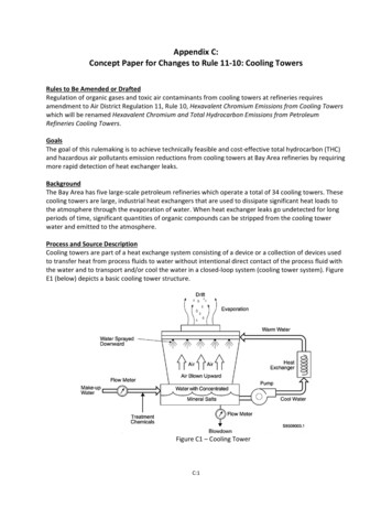
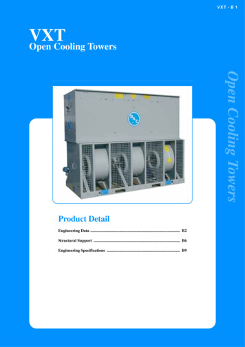
KLM TechnologyGroupPractical EngineeringGuidelines forProcessing Plant SolutionsPage 5 of 52COOLING TOWER SELECTION ANDSIZINGRev: 01ENGINEERING DESIGN GUIDELINESJuly 2011Cooling TowerCooling towers are heat removal devices used to transfer process waste heat to theatmosphere. Cooling towers make use of evaporation whereby some of the water isevaporated into a moving air stream and subsequently discharged into theatmosphere. As a result, the remainder of the water is cooled down significantly.Fig 1. Schematic diagram of a cooling water systemThere are several important factors that govern the operation of cooling tower:-The dry-bulb and wet-bulb temperatures of the air-The temperature of warm water-The efficiency of contact between air and water in terms of the volumetric masstransfer coefficient and the contact time between the air and the water-The uniformity of distribution of the phases within the tower-The air pressure drop-The desired temperature of the cooled waterThese design guideline are believed to be as accurate as possible, but are very general and not for specific designcases. They were designed for engineers to do preliminary designs and process specification sheets. The finaldesign must always be guaranteed for the service selected by the manufacturing vendor, but these guidelines willgreatly reduce the amount of up front engineering hours that are required to develop the final design. The guidelinesare a training tool for young engineers or a resource for engineers with experience.This document is entrusted to the recipient personally, but the copyright remains with us. It must not be copied,reproduced or in any way communicated or made accessible to third parties without our written consent.
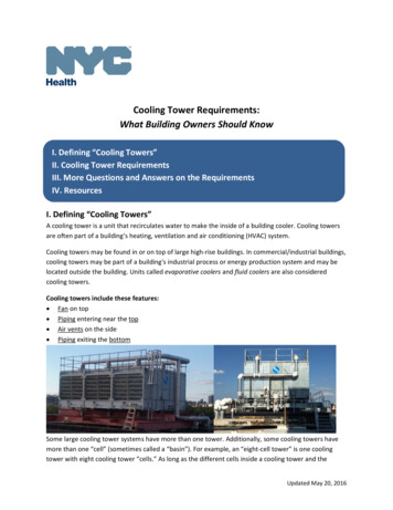
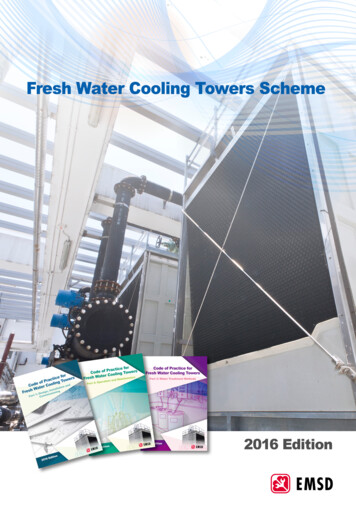
KLM TechnologyGroupPractical EngineeringGuidelines forProcessing Plant SolutionsPage 6 of 52COOLING TOWER SELECTION ANDSIZINGRev: 01ENGINEERING DESIGN GUIDELINESJuly 2011Air might enter the tower driven by a density gradient (natural draft), might be pushedinto the tower (forced draft) at the base or drawn into the tower (induced draft)assisted by a fan. Several types of cooling towers have been designed on the basis ofthe above factors and operating strategies.The cooling tower might be classified into several types, but they are broadlycategorized by following considerations:1. Whether there is direct or indirect contact2. The mechanism used to provide the required airflow3. The relative flow paths of air and water4. The primary materials of construction5. the type of heat transfer media applied6. The tower’s physical shapeGeneral classification of cooling tower is pictured below:Fig 2. Classifications of cooling towersThese design guideline are believed to be as accurate as possible, but are very general and not for specific designcases. They were designed for engineers to do preliminary designs and process specification sheets. The finaldesign must always be guaranteed for the service selected by the manufacturing vendor, but these guidelines willgreatly reduce the amount of up front engineering hours that are required to develop the final design. The guidelinesare a training tool for young engineers or a resource for engineers with experience.This document is entrusted to the recipient personally, but the copyright remains with us. It must not be copied,reproduced or in any way communicated or made accessible to third parties without our written consent.
KLM TechnologyGroupPractical EngineeringGuidelines forProcessing Plant SolutionsPage 7 of 52COOLING TOWER SELECTION ANDSIZINGRev: 01ENGINEERING DESIGN GUIDELINESJuly 2011Classification by buildPackage TypeThis type of cooling towers is preassembled and can be simply transported on trucksas they are compact machines. The capacity of package type towers are limited andfor that reason, they are usually preferred by facilities with low heat rejectionrequirements such as food processing plants, textile plants, buildings like hospitals,hotels, malls, chemical processing plants, automotive factories etc. Due to theintensive use in domestic areas, sound level control is a relatively more importantissue for package type cooling towers.Field Erected TypeField erected type cooling towers are usually preferred for power plants, steelprocessing plants, petroleum refineries, and petrochemical plants. These towers arelarger in size compared to the package type cooling towers.Classification based on heat transfer methodWet Cooling TowerThis type of cooling tower operates based on evaporation principle. The working fluidand the evaporated fluid (usually water) are one and the same. In a wet cooling tower,the warm water can be cooled to a temperature lower than the ambient air dry-bulbtemperature, if the air is relatively dry.Dry Cooling TowerThis tower operates by heat transfer through a surface that separates the working fluidfrom ambient air, such as in a tube to air heat exchanger, utilizing convective heattransfer. Dry cooling tower does not use evaporation.Fluid CoolerThis tower passes the working fluid through a tube bundle, upon which clean water issprayed and a fan-induced draft applied. The resulting heat transfer performance ismuch closer to that of a wet cooling tower, with the advantage provided by a drycooler of protecting the working fluid from environmental exposure and contamination.These design guideline are believed to be as accurate as possible, but are very general and not for specific designcases. They were designed for engineers to do preliminary designs and process specification sheets. The finaldesign must always be guaranteed for the service selected by the manufacturing vendor, but these guidelines willgreatly reduce the amount of up front engineering hours that are required to develop the final design. The guidelinesare a training tool for young engineers or a resource for engineers with experience.This document is entrusted to the recipient personally, but the copyright remains with us. It must not be copied,reproduced or in any way communicated or made accessible to third parties without our written consent.
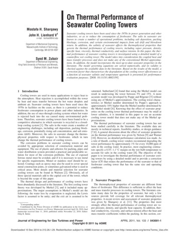
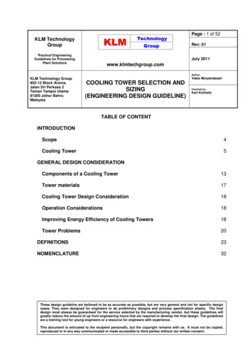
KLM TechnologyGroupPractical EngineeringGuidelines forProcessing Plant SolutionsPage 8 of 52COOLING TOWER SELECTION ANDSIZINGRev: 01ENGINEERING DESIGN GUIDELINESJuly 2011Classification based on air draftAtmospheric TowerAn atmospheric tower consist of a big rectangular chamber with two opposite louveredwalls. The tower is packed with a suitable tower fill. Atmospheric air enters the towerthrough the louvers driven by its own velocity. An atmospheric tower is cheap butinefficient. Its performance largely depends upon the direction and velocity of wind.Fig 3. Atmospheric cooling towerNatural Draft TowerThe natural draft or hyperbolic cooling tower makes use of the difference intemperature between the ambient air and the hotter air inside the tower. As hot airmoves upwards through the tower (because hot air rises), fresh cool air is drawn intothe tower through an air inlet at the bottom.These design guideline are believed to be as accurate as possible, but are very general and not for specific designcases. They were designed for engineers to do preliminary designs and process specification sheets. The finaldesign must always be guaranteed for the service selected by the manufacturing vendor, but these guidelines willgreatly reduce the amount of up front engineering hours that are required to develop the final design. The guidelinesare a training tool for young engineers or a resource for engineers with experience.This document is entrusted to the recipient personally, but the copyright remains with us. It must not be copied,reproduced or in any way communicated or made accessible to third parties without our written consent.
KLM TechnologyGroupPractical EngineeringGuidelines forProcessing Plant SolutionsPage 9 of 52COOLING TOWER SELECTION ANDSIZINGRev: 01ENGINEERING DESIGN GUIDELINESJuly 2011A natural draft tower is so called because natural flow of air occurs through the tower.Two factors are responsible for creating the natural draft:- a rise in temperature and humidity of air in the column reduces its density, and- the wind velocity at the tower bottom.Due to the layout of the tower, no fan is required and there is almost no circulation ofhot air that could affect the performance. But in some cases, a few fans are installedat the bottom to enhance the air flow rate. This type of tower is called ‘fan-assisted’natural draft tower.The hyperbolic shape is made because of the following reasons:- more packing can be fitted in the bigger area at the bottom of the shell;- the entering air gets smoothly directed towards the centre because of the shape ofthe wall, producing a strong upward draft;- greater structural strength and stability of the shell is provided by this shape.The pressure drop across the tower is low and the air velocity above the packing mayvary from 1-1.5 m/s. The concrete tower is supported on a set of reinforced concretecolumns. Concrete is used for the tower shell with a height of up to 200 m. Thesecooling towers are mostly only for large heat duties because large concrete structuresare expensive.Fig 4 (a) Cross flow and (b) counter flow natural draft cooling towerThese design guideline are believed to be as accurate as possible, but are very general and not for specific designcases. They were designed for engineers to do preliminary designs and process specification sheets. The finaldesign must always be guaranteed for the service selected by the manufacturing vendor, but these guidelines willgreatly reduce the amount of up front engineering hours that are required to develop the final design. The guidelinesare a training tool for young engineers or a resource for engineers with experience.This document is entrusted to the recipient personally, but the copyright remains with us. It must not be copied,reproduced or in any way communicated or made accessible to third parties without our written consent.
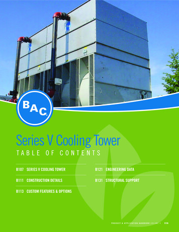
KLM TechnologyGroupPractical EngineeringGuidelines forProcessing Plant SolutionsPage 10 of 52COOLING TOWER SELECTION ANDSIZINGRev: 01ENGINEERING DESIGN GUIDELINESJuly 2011Mechanical Draft Cooling TowerBecause of their huge shape, construction difficulties and cost, natural draft towershave been replaced by mechanical draft towers in many installations. Mechanical drafttowers have large fans to force or draw air through circulated water. The water fallsdownwards over fill surfaces, which helps increase the contact time between the waterand the air. Cooling rates of mechanical draft towers depend upon variousparameters; such as fan diameter and speed of operation, fills for system resistance,etc.There are two different classes of mechanical draft cooling towers:a. Forced draftIt has one or more fans located at the tower bottom to push air into the tower.During operation, the fan forces air at a low velocity horizontally through thepacking and then vertically against the downward flow of the water that occurs oneither side of the fan. The drift eliminators located at the top of the tower removewater entrained in the air. Vibration and noise are minimal since the rotatingequipment is built on a solid foundation. The fans handle mostly dry air, greatlyreducing erosion and water condensation problems.Fig 5. Forced draft cooling towerb. Induced draftA mechanical draft tower with a fan at the discharge which pulls air through tower.The fan induces hot moist air out the discharge. This produces low entering andhigh exiting air velocities, reducing the possibility of recirculation in whichdischarged air flows back into the air intake.These design guideline are believed to be as accurate as possible, but are very general and not for specific designcases. They were designed for engineers to do preliminary designs and process specification sheets. The finaldesign must always be guaranteed for the service selected by the manufacturing vendor, but these guidelines willgreatly reduce the amount of up front engineering hours that are required to develop the final design. The guidelinesare a training tool for young engineers or a resource for engineers with experience.This document is entrusted to the recipient personally, but the copyright remains with us. It must not be copied,reproduced or in any way communicated or made accessible to third parties without our written consent.
KLM TechnologyGroupPractical EngineeringGuidelines forProcessing Plant SolutionsPage 11 of 52COOLING TOWER SELECTION ANDSIZINGRev: 01ENGINEERING DESIGN GUIDELINESJuly 2011Fig 6. Induced draft cooling towerClassification based on air flow patternCrossflowCrossflow is a design in which the air flow is directed perpendicular to the water flow.Air flow enters one or more vertical faces of the cooling tower to meet the fill material.Water flows (perpendicular to the air) through the fill by gravity. The air continuesthrough the fill and thus past the water flow into an open plenum area. A distribution orhot water basin consisting of a deep pan with holes or nozzles in the bottom is utilizedin a crossflow tower. Gravity distributes the water through the nozzles uniformlyacross the fill material.These design guideline are believed to be as accurate as possible, but are very general and not for specific designcases. They were designed for engineers to do preliminary designs and process specification sheets. The finaldesign must always be guaranteed for the service selected by the manufacturing vendor, but these guidelines willgreatly reduce the amount of up front engineering hours that are required to develop the final design. The guidelinesare a training tool for young engineers or a resource for engineers with experience.This document is entrusted to the recipient personally, but the copyright remains with us. It must not be copied,reproduced or in any way communicated or made accessible to third parties without our written consent.
KLM TechnologyGroupPractical EngineeringGuidelines forProcessing Plant SolutionsPage 12 of 52COOLING TOWER SELECTION ANDSIZINGRev: 01ENGINEERING DESIGN GUIDELINESJuly 2011Fig 7. Crossflow type designCounterflowIn a counterflow design the air flow is directly opposite to the water flow (see diagrambelow). Air flow first enters an open area beneath the fill media and is then drawn upvertically. The water is sprayed through pressurized nozzles and flows downwardthrough the fill, opposite to the air flow.Fig 8. Counterflow type designThese design guideline are believed to be as accurate as possible, but are very general and not for specific designcases. They were designed for engineers to do preliminary designs and process specification sheets. The finaldesign must always be guaranteed for the service selected by the manufacturing vendor, but these guidelines willgreatly reduce the amount of up front engineering hours that are required to develop the final design. The guidelinesare a training tool for young engineers or a resource for engineers with experience.This document is entrusted to the recipient personally, but the copyright remains with us. It must not be copied,reproduced or in any way communicated or made accessible to third parties without our written consent.
KLM TechnologyGroupPractical EngineeringGuidelines forProcessing Plant SolutionsPage 13 of 52COOLING TOWER SELECTION ANDSIZINGRev: 01ENGINEERING DESIGN GUIDELINESJuly 2011GENERAL DESIGN CONSIDERATIONComponents of A Cooling TowerStructural Components [1]Most cooling systems are very vulnerable to corrosion. They contain a wide variety ofmetals and circulate warm water at relatively high linear velocities. Both of thesefactors accelerate the corrosion process. Deposits in the system caused by silt, dirt,debris, scale and bacteria, along with various gases, solids and other matter dissolvedin the water all serve to compound the problem. Even a slight change in the coolingwater pH level can cause a rapid increase in corrosion. Open recirculating systemsare particularly corrosive because of their oxygen-enriched environment.The structural components of cooling tower such as: cold water basin, framework,water distribution system, fan deck, fan cylinders, mechanical equipment supports, fill,drift eliminators, casing, and louvers.1. Cold water basinThe cold water basin has two fundamentally important functions: collecting the coldwater following its transit of the tower, and acting as the tower’s primaryfoundation.2. Tower frameworkThe most commonly used materials for the framework of field-erected towers arefiberglass, wood, and concrete, with steel utilized infrequently to conform to a localbuilding code, or to satisfy a specific preference.3. Water distribution systemLines might be buried to minimize problem of thrust loading, thermal expansionand freezing; or elevated to minimize cost of installation and repair. In either case,the risers to the tower inlet must be externally supported, independent of the towerstructure and piping.4. Fan deckThe fan deck is considered a part of the tower structure, acting as a diaphragm fortransmitting dead and live loads to the tower framing. It also provides a platform forthe support of the fan cylinders, as well as an accessway to the mechanicalThese design guideline are believed to be as accurate as possible, but are very general and not for specific designcases. They were designed for engineers to do preliminary designs and process specification sheets. The finaldesign must always be guaranteed for the service selected by the manufacturing vendor, but these guidelines willgreatly reduce the amount of up front engineering hours that are required to develop the final design. The guidelinesare a training tool for young engineers or a resource for engineers with experience.This document is entrusted to the recipient personally, but the copyright remains with us. It must not be copied,reproduced or in any way communicated or made accessible to third parties without our written consent.
KLM TechnologyGroupPractical EngineeringGuidelines forProcessing Plant SolutionsPage 14 of 52COOLING TOWER SELECTION ANDSIZINGRev: 01ENGINEERING DESIGN GUIDELINESJuly 2011equipment and water distribution system. Fan deck materials are customarilycompatible with the tower framework.5. Fan cylinderFan cylinder directly affects the proper flow of air through the tower. Its efficienciescan be severely reduced by a poorly designed fan cylinder, or significantlyenhanced by a well-designed one.6. Mechanical equipment supportsCustomary material for the unitized supports is carbon steel, hot-dip galvanizedafter fabrication, with stainless steel construction available at significant additionalcost.7. Fill (heat transfer surface)Fill (heat transfer surface) is able to promote both the maximum contact surfaceand the maximum contact time between air and water determines the efficiency ofthe tower. The two basic fill classifications are splash type and film type.Splash type fill breaks up the water, and interrupts its vertical progress, by causingit to cascade through successive offset levels of parallel splash bars. It ischaracterized by reduced air pressure losses, and is not conducive to logging.However, it is very sensitive to inadequate support.Film type fill causes the water to spread into a thin film, flowing over large verticalareas, to promote maximum exposure to the air flow. It has capability to providemore effective cooling capacity within the same amount of space, but is extremelysensitive to poor water distribution.8. Drift eliminatorDrift eliminators remove entrained water from the discharge air by causing it tomake sudden changes in direction. The resulting centrifugal force separates thedrops of water from air, depositing them on the eliminator surface, from which theyflow back into the tower.Eliminator are normally classified by the number of directional changes or“passes”, with an increase in the number of passes usually accompanied by anincrease in pressure drop.9. CasingA cooling tower casing acts to contain water within the tower, provide an airplenum for the fan, and transmit wind loads to the tower framework. It must havediaphragm strength, be watertight and corrosion resistant, have fire retardantqualities, and also resist weathering.These design guideline are believed to be as accurate as possible, but are very general and not for specific designcases. They were designed for engineers to do preliminary designs and process specification sheets. The finaldesign must always be guaranteed for the service selected by the manufacturing vendor, but these guidelines willgreatly reduce the amount of up front engineering hours that are required to develop the final design. The guidelinesare a training tool for young engineers or a resource for engineers with experience.This document is entrusted to the recipient personally, but the copyright remains with us. It must not be copied,reproduced or in any way communicated or made accessible to third parties without our written consent.
KLM TechnologyGroupPractical EngineeringGuidelines forProcessing Plant SolutionsPage 15 of 52COOLING TOWER SELECTION ANDSIZINGRev: 01ENGINEERING DESIGN GUIDELINESJuly 201110. LouversEvery well-designed crossflow tower is equipped with inlet louvers, whereascounterflow towers are only occasionally required to have louvers. Their purpose isto retain circulating water within the confines of the tower, as well as to equalize airflow into the fill.Mechanical Components [1]1. FansCooling tower fans must move large volumes of air efficiently, and with minimumvibration. The materials of manufacture must not only be compatible with theirdesign, but must also be capable of withstanding the corrosive effects of theenvironment in which the fans are required to operate.a. Propeller fans: They have ability to move vast quantities of air at the relativelylow static pressure encountered. They are comparatively inexpensive, may beused on any size tower, and can develop high overall efficiencies; but theirapplication naturally tends to be limited by the number of projects of sufficientsize to warrant their consideration.b. Automatic variable-pitch fans: They are able to vary airflow through the tower inresponse to a changing load or ambient condition.c. Centrifugal fans: They are usually used on cooling towers designed for indoorinstallations; their capability to operate against relatively high static pressuresmakes them particularly suitable for that type of application. However, theirinability to handle large volumes of air, and their characteristically high inputhorsepower requirement limits their use to relatively small applications.All propeller type fans operate in accordance with common laws:- The capacity varies directly as the speed ratio, and directly as the pitch angle ofthe blades relative to the plane of rotation.- The static pressure varies as the square of the capacity ratio.- The fan horsepower varies as the cube of the capacity ratio.- At constant capacity, the fan horsepower and static pressure vary directly withair density.2. Speed reducersThe optimum speed of a cooling tower fan seldom coincides with the most effici
Field erected type cooling towers are usually preferred for power plants, steel processing plants, petroleum refineries, and petrochemical plants. These towers are larger in size compared to the package type cooling towers. Classification based on heat transfer method Wet Cooling Tower This type of cooling tower operates based on evaporation .