Transcription
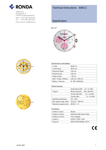
Technical Instructions 5050.CSpecification12 ½'''Dimensions and batteryø Total28.60 mmø Case fitting28.00 mmMovement height4.40 mmMovement rest0.60 mmHeight of stem1.90 mmStem: Thread / Distance0.90 mm / 0.90 mmBattery / AutonomyNr. 395 / 48 MonthsPerformancesTorque TSmall second (M1):4.0 - 6.7 µNmMinute hand (M1):200 - 300 µNmCounter (M2, M4):Counter (M3):Operating temperature0 C - 50 CRes. against magn. fields18.8 Oe 1500 A/mResistance against shockNIHS 91 - 103.0 - 4.6 µNm1.5 - 2.5 µNmFunctions20 Mar 2006Position I (crown)NeutralPosition II (crown)Setting the date (quick mode)Position III (crown)Time, weekdayPusher ASTART / STOP / ADDPusher BZERO POSITIONING / SPLIT1
Technical Instructions 5050.CAssembling1. 3305.282.COCannon pinion with driver (Aig 2)Moebius 8200 greace must be placed between the steel tube and thebrass wheel. The steel tube must be placed into the center hole of themain plate.2. 3301.244Hour wheel (counter 24h)3. 2030.017.COCentre bridgeUse one screw 4000.250 to fix the center bridge.4. 3001.041Sliding pinionThe sliding ponion must be holded using a tweezers, untill the stem isinserted.A5. 3000.177.COHandsetting stemPrior to the insertion of the stem, some greace must be placed on thesquare part of the stem.6. 3017.049Setting leverThe cam on the setting lever must be inserted into the cut out on thestem. (the setting lever must be greaced)7. 3905.049Setting lever jumper (3 positions)The setting lever jumper (3 positions) must be tensioned and insertedinto the setting lever. Use one screw 4000.250 to fix the setting lever.8. 3015.070Yoke (3 positions)The yoke must be inserted below, into the cutout of the sliding pinion.The oposite end of the yoke must be positioned arround the pillar ofsetting lever. (Use Moebius 8200 to greaced the yoke)9. 3406.030Pusher jumper2 pieces. Use Jismaa 124 to greace the pusher jumper.10. 3622.040Stator11. 3622.039Stator (counter 6h and 9h and chrono)B3 pieces12. 4000.250Screw13. 3603.065Plastic bracketUse 4 screws 4000.25014. 4000.250Screw15. 3715.094.RKRotor (centre and chrono)Use an antimagnetic tweezers to place the 2 rotors.C20 Mar 200616. 3147.046.COIntermediate wheel17. 3136.142.COSecond wheel (long)2
Technical Instructions 5050.CAssembling18. 3147.047.COIntermediate wheel (chrono)19. 3136.144.COChronograph wheel (Aig 2)20. 3122.056.COThird wheel21. 2020.148Train wheel bridgeAttention: Prior to the fastening process of the bridge, all 7 pins of thewheels must be visible in the 7 holes in the bridge. Use 3 screws4000.250.D22. 3715.095.RKRotor (counter 6h and 9h)Use an antimagnetic tweezers to place the rotor.23. 3147.048.COIntermediate wheel (counter)24. 3007.056.COMinute wheel (counter 24h)25. 3402.008.COMinute counting wheel26. 2020.149Counter train wheel bridgeAttention: Prior to the fastening process of the bridge, all 4 pins of thewheels must be visible in the 4 holes of the bridge. Use 3 screws4000.250.E27. 3715.095.RKRotor (counter 6h and 9h)Use an antimagnetic tweezers to place the rotor.28. 3147.053.COIntermediate wheel (counter 1/10sec)29. 3402.009.COCounting wheel 1/10 sec30. 2020.149Counter train wheel bridgeAttention: Prior to the fastening process of the bridge, all 4 pins of thewheels must be visible in the 4 holes of the bridge. Use 3 screws4000.250.31. 4000.250ScrewF20 Mar 20063
Technical Instructions 5050.CAssembling32. 9014.000Moebius 9014Use Moebius 9014 on bearing of all rubis33. 3621.053.RKCoilThe wire of the coil (red area) is very sensitiv to mechanical impacts.Hold the coil only ouside the red area. Fix the coil by 1screw 4000.250.34. 3621.054.RKCoil (counter 9h and chrono)The wire of the coil (red area) is very sensitiv to mechanical impacts.Hold the coil only ouside the red area. Fix each of the 2 coils by 1screw4000.250.35. 3621.055.RKCoil (counter 6h)The wire of the coil (blue area) is very sensitiv to mechanical impacts.Hold the coil only ouside the blue area. Fix the coil by 1screw4000.250.36. 4000.250Screw37. 3603.034Battery insulator38. 3612.144.5050Electronic moduleGAfter assembly of the electronic module it is the best time to performthe electrical measurements. Use 5 screws 4000.248 to fix theelectronic module.39. 4000.248Screw40. 3603.069Circuit insulator41. 3601.107Pusher contact springMake shure, that the pusher contact spring is placed correctly onto thepillars.H42. 2130.137.5050.CElectronic module cover (counter 6h/9h)Make shure, that the pusher contact spring is not displaced duringattachment of the electronic module cover. Use 3 screws 4000.250 tofix the electronic module cover43. 3600.010BatteryUse a plastic tweezers to place the battery (to avoid short circuit ofbattery).44. 3601.109Bridle Insert the two brackets of the battery bridle under the electronic modulecover and fasten the battery bridle by 1 screw 4000.250.45. 4000.250ScrewI20 Mar 20064
Technical Instructions 5050.CAssembling46. 2000.574.COMain plate47. 9014.000Moebius 9014Use Moebius 9014 on bearing of all rubis48. 3004.164Setting wheelUse Moebius 9020 on both setting wheels49. 3007.054.COMinute wheelUse Moebius 902050. 2130.143Minute train bridgeUse 2 screws 4000.305J51. 4000.305Screw52. 3004.181Tens indicator driving wheelThe short tooth of the tens indicator driving wheel must point to thecenter of the movement.53. 3500.059Tens jumperMoebius 8200 greace must be placed between the tens jumper and thetens indicator driving wheel.54. 2130.142Tens jumper maintaining plateMake shure, that the tens indicator driving wheel is not blocked prior tothe fastening process. Use 2 screws 4010.306. Place the spring loadedbracket outside of the tens jumper.55. 4010.306Screw56. 3301.242Hour wheel (Aig 2)KUse Moebius 902057. 3315.016Hour wheel friction springMust be placed onto the hour wheel58. 3004.176.CODate indicator driving wheelMoebius 9020 must be used in the center of this wheel59. 3500.049Date jumperMoebius 8200 greace must be placed between the date jumper and thedate jumper spring20 Mar 20065
Technical Instructions 5050.CAssembling60. 3504.214.ADUnits indicatorTeaths must be greaced using Moebius 8200. The "half moon" cut outon the unit indicator must point to the stem (position 3h).61. 3147.054Tens intermediate wheel62. 2130.163Date indicator maintaining plateuse 1 screw 4000.28263. 3905.050Date jumper springInsert the spring into the opening of the date indicator maintaining plateL64. 3504.215.ADTens indicator (T3/G12)The "half moon" cut out on the tens indicator must point to the stem(position 3h).65. 3500.055Day jumper66. 3004.175Day finger67. 2130.162Date mechanism maintaining plateAssure that the tens intermediate wheel is not blocked, prior to thefastening process. Use 2 screws 4000.312 and 1 screw 4000.300 to fixthe date indicator maintaining plate.68. 3508.155Day indicator69. 2130.164Day indicator maintainin plate70. 3506.072Dial support71. 4000.250Screw72. 4000.282Screw73. 4000.300Screw74. 4000.311Screw75. 4000.312Screw76. 9010.000Moebius 8200MNMicrogliss D5 can be used77. 9018.000Jismaa 124Greace Moebius or Microgliss D5 an be used78. 9020.00020 Mar 2006Moebius 90206
Technical Instructions 5050.CElectrical checkingVoltage of batteryConsumption (M1) of movem. (Pos. I)1.50 - 1.55 V0.75 - 1.3 µABattery testBattery must be removed from movementSupply power from measurement equipment (1,55 V)Consumption (M1) of movem. (Pos. III)Lowest voltage for movement (M1)0.1 - 0.3 µAless than 1.3VLower limit for operation of movementSupply power from measurement equipment (1,55 V)Adjust voltage on the measuring eqipement to 1.55 V. The slowly reduce thetension untill the movement stopsAccuracy (seconds / month)Resistance of the coil: motor 1 (movem.)-10/ 20 s/M1.9 - 2.1 kOhmRef. 3621.053.RKCheck for a time of minimal 60 seconds20 Mar 2006The resistance of the coil can be measured on the electronics (M1) or directly onthe coils (electronic module must be removed).7
Technical Instructions 5050.CElectrical checkingResistance of the coil: motor 2 (counter)Resistance of the coil: motor 3 (counter)2.2 - 2.4 kOhm2.2 - 2.4 kOhmRef. 3621.054.RKRef. 3621.055.RKThe resistance of the coil can be measured on the electronics (M2) or directly onthe coils (electronic module must be removed).The resistance of the coil can be measured on the electronics (M3) or directly onthe coils (electronic module must be removed).Resistance of the coil: motor 4 (counter)Coil insulation: motor 1, 2, 3 and 42.2 - 2.4 kOhm. kOhmRef. 3621.054.RKindefinite highThe resistance of the coil can be measured on the electronics (M4) or directly onthe coils (electronic module must be removed).The resistance between each coil and pole must be measured (electronicmodule must be removed)20 Mar 20068
Technical Instructions 5050.CTest of the motorsAccelerated test of movement (M1)1. Activation of control mode (pos III)1.55 V8 steps / sec.During 1-3 the movement must by supplied continiouslyTo activate this test mode, the corresponding test point must be connected to the-PoleConnect points A B simultaneous for min. 2 seconds to the Pol. Do notinterrupt the supply voltage - stem pos III)2. Check of active counter3. Change to the next counter1.3 VDuring connection of Pol to A, the active counter is turning.Short contact with pole to point BReduced the supply voltage to 1.3V to check the proper function of the counter.If the power supply is disconnected, the control mode must be starded again section 1.Change of active counter: M2-M3-M4-M2-M3- .After a timout of approx. 30seconds since last contact, the control mode will be terminated.20 Mar 20069
Technical Instructions 5050.C Assembling 20 Mar 2006 3 18. 3147.047.CO Intermediate wheel (chrono) 19. 3136.144.CO Chronograph wheel (Aig 2) 20. 3122.056.CO Third wheel 21. 2020.148 Train wheel bridge Attention: Prior to the fastening process of the bridge, all 7 pins of the wheels must be visible in the 7 holes in the bridge. Use 3 screws 4000 .