Transcription
1Peng XinIEC 61850 Testing and DocumentationInformation Technology2010
2ForewordThis thesis would not be possible without the help of many people such as Dr. SmailMenani from VAMK OY who inspired me with the project idea and technical support.Many thanks to Mr. Olavi Vahamaki from VAMP OY, who assisted me whenever Iface difficulties with the VAMP relay. Not to forget mentioning my teachers of thetelecommunication module, Dr. Gao Chao, Mr. Virtanen Antti and Mr. Jukka Matilafor their valuable instructions during my studies. Special thanks to Vaasa Universityof Applied Sciences for giving me the opportunity and possibilities to succeed in mystudies.At last, thanks to my family and teammates who gave a lot of support andencouragement during the critical moments.
3ABBREVIATIONSDSData SetGOOSEGeneric Object Oriented Substation EventsGCBGOOSE Control BlockIEDIntelligent Electronic DeviceLDLogical DeviceLNLogical NodeMMSManufacturing Message SpecificationASN.1Abstract SyntaxBERBasic Encoding RulePDUProtocol Data UnitAPDUApplication Protocol Data UnitFCFunctional ConstraintFCDAFunctional Constraint Data Attribute
4VAASAN AMMATTIKORKEAKOULUUNIVERSITY OF APPLIED SCIENCESDegree Program of Information TechnologyABSTRACTAuthor: Peng XinTitle: GOOSE Transmission Laboratory Exercises and GOOSE Messages DecodingYear: 2010Language: EnglishPages: 43Supervisor: Menani SmailThe purpose of this thesis is to develop laboratory experiments for a datatransmission course. The laboratory experiments deals with the generation of GOOSEmessages using VAMP relays on the one hand and the decoding of the generatedmessages on the other hand. The decoding scheme includes theoretical overview,instructions and practical description related to the laboratory exercises.The methodology of achieving the result is to intercept proper data matches to thestructure of GOOSE through a series of physical connection and softwareconfiguration. The set up of the laboratory exercise is based on the connectionbetween a Vamp Relay, a Laptop and a set of programs such as Vampset, IEC 61850Simple Tester, GOOSE Sender and Wireshark. These programs are used to configureand detect GOOSE messages. Through physical connection and proper configurationof the devices and tools, the data traffic has to be detected and decoded.The project is divided into 3 tasks: pre-exercise for telecommunication course,laboratory exercise for telecommunication course and decoding GOOSE messages fortelecommunication course. In this thesis, the task is to filter GOOSE messages anddecode them according to GOOSE structure.Laboratory exercises documentation is not included in this document but deliveredseparately to the concerned teacher to be used in the laboratory course.Keyword GOOSE, Telecommunication, Decode, Target, Analyze, Communication
5CONTENTS1. LABORATORY EXERCISES DESCRIPTION . 61.1. Laboratory Distribution . 61.2. Technical Laboratory Architecture . 71.3. Devices & Software . 82.3.GOOSE MESSAGES SPECIFICATION . 102.1.Transmission principle of GOOSE messages . 102.2.GOOSE Data Structure . 11PROCEDURE OF 3 LABORATORIES FOR DETECTING GOOSE MESSAGES . 143.1.Laboratory 1 Activate DI‟s to Detect messages . 153.1.1. Setting in Read Menu . 163.1.2. Setting in Control Menu . 173.1.3. Settings in Report Menu . 183.2.Switchgear to simulate GOOSE messages . 183.2.1. GOOSE Sender Configuration for GOOSE . 183.2.2. Vampset Configuration for GOOSE . 193.2.3. GOOSE in Wireshark . 233.3. Trip/Block Functional Simulation for GOOSE . 253.3.1. Physical Connection . 253.3.2. Software Configuration& Test Procedure . 264.5.GOOSE MESSAGES ANALYSIS . 324.1.GOOSE message in Exercise 2 . 334.2.GOOSE message in Exercise 3 . 38CONCLUSION . 41REFERENCES: . 42
61. Laboratory Exercises DescriptionThere are 3 telecommunication laboratory exercises in this project. The first exerciseis to activate the digital inputs using RJ45 cable as a transmission medium. This is thebasic experiment to find the method to detect required messages. The second exerciseutilizes the switchgear to adjust the connection and test for GOOSE transmissionbetween the Vamp Relay and the laptop. The last exercise realizes the Trip and Blockfunctions of the protection Relay by applying the function generator which canchange the values of frequency and amplitude. These exercises not only present theoutcome from the researched procedure, but also provide different kinds of methodsto detect GOOSE messages.1.1. Laboratory DistributionLab 1: Activate to detect message between Relay and Laptop1. Get familiar to the basic configuration on relays2.RJ45 Cable connection between logical nodes in rear panelLab 2: Switchgear to simulate GOOSE message1.Connect a switch to Vamp Relay.2.Set the right configuration in software.3.Intercept GOOSE messages from Wireshark and analyze the messages.Give interrelated analysis from this exercise.
7Lab 3: Trip/Block function1. Get familiar to datasheet of the relay.2. Connect the power supply to the relay as described in the instructions.3. Give correct configuration in Vampset and compare the result to theprinciple.1.2. Technical Laboratory Architecture
81.3. Devices & SoftwareDevices:Vamp 257 Feeder ManagerVamp 257 Feeder Manager is the protection relay used for dangerous prevention insubstation. There are series of interrelated choice to set the address, values of voltage,status, and mode and so on. The overview of current information represents whether thesettings are requisite in the function. The values in Vamp can be changed by inputting thesecret number. Otherwise, it keeps the default information with the initial configurationand cannot be altered without the password. Physical connection and digital inputs can beenabled on the rear panel of the Vamp 257.Vamp257 Feeder Manager(reference:www.vamp.fi)Function GeneratorThe function generator produces various patterns of voltage at a variety of frequenciesand amplitude. It is used for testing safety of the circuit to input signals.Software:
9VAMPSETVAMPSET comprises all of the attributes of GOOSE Control Block. GOOSE Enable,GOOSE name, Data Sets included in the attributes can be applied in this program. Thereis a string of menu which gives detailed information of each attribute and application.From these settings, the Vamp Relay is controlled by Vampset. This program shows thesame parameters as in the Vamp Relay. Logical connection is created in tag logic toachieve the aim of GOOSE transmission between the devices.IEC61850 Simple TesterThis simple program is used to apply the Logic Nodes, Object and Attributes. It isdivided into 5 parts: Host address, Read, Control, Report and GOOSE. The value showsthe result monitored from the communication between the switchgear device and theVamp Relay. The Report Control Block reports whether there‟s emergency happens ifsome status changes.GOOSE SenderGOOSE Sender is a convenient program for GOOSE transmission. It simulates aGOOSE message directly from the Vamp Relay to other devices. Through theinterrelated configuration in the devices, GOOSE Sender makes the communication withGOOSE messages. The request and response are formed by this simulated transmission.Wireshark
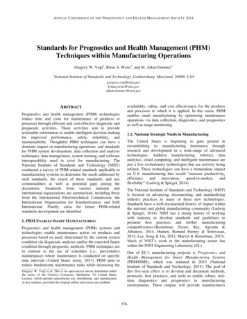
10Wireshark is an analyzer of network transmission. It filters useful protocol for usersto display the packets needed. Updating the new versions of this program, morefunctions and details gives more information to the user. This software helps tomonitor every frame with the exact time, address and path. Even the structures ofsome infrequent protocols can be excavated by Wireshark. For saving time in filteringuseful messages, it has the function to capture the protocol needed from a largenumber of frames.2. GOOSE messages Specification2.1.Transmission principle of GOOSE messagesGOOSE (Generic Object Oriented Substation Event) is a transmission of exchanginga wide range of data in a dataset. With a fast connection and less communicationservice which is used for the transfer of time-critical data, the communicationnetwork updates the content of messages as soon as the values changed. In order tomore applications, GOOSE message exchange is based on the multicast applicationassociation. This routing technique provides to deliver messages from one publisherto one or many subscribers. The publisher is referred to as a sender who requests witha group of members in a dataset. These requests are sent to the transmission buffer ofthe publisher, afterwards this buffer is updated with the publish service and the valuesare transmitted by a GOOSE message. On the receiver, the reception buffer in thesubscriber receives the new values and it is updated by mapping services.
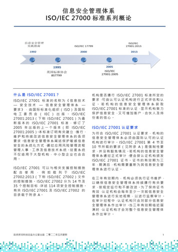
11Multicast Application(Reference: International Standard IEC61850-5)Publish/Subscribe systems are useful: first of all, while unreliable deliverymechanisms are present, they distribute large quantities of time-critical informationwell and quickly. Then it can handle very complex data flow patterns. Finally manyto-many model is very efficient in both bandwidth and latency.2.2.GOOSE Data StructureThe following figure is an overview of ISO/IEC 8802-3 frame structure for GSEmanagement and GOOSE. In a GOOSE message, the header MAC comprises 12bytes, first 6 bytes are destination address and the last 6 bytes are source address.Next 14 bytes are Priority tags which present Ethertype, Application ID, messagelength and reserved number. Besides the 26 bytes enumerate the fundamentalinformation of the GOOSE message, from byte 27 to the unlimited number of data
12are decoded with APDU (Application Protocol Data Unit). The detailed explanationof GOOSE messages intercepted from the outcome in the laboratories will berevealed in the subsequent chapter.ISO/IEC 8802-3 frame format(Reference: International Standard IEC61850-5)
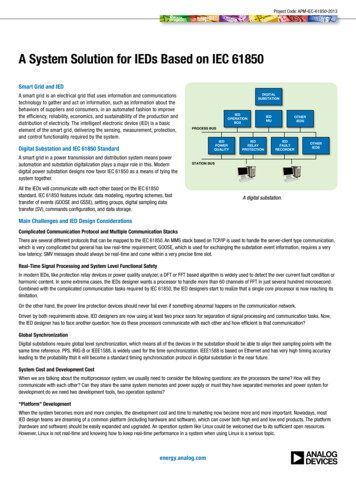
13In APDU structure, there are 13 labels which display the specific content in theconfiguration of the experiments. The labels stand for the attributes of GOOSEControl Block.APDU StructureThis APDU structure is referred from INTERNATIONAL STANDARD 61850-8-1.
143. Procedure of 3 Laboratories for Detecting GOOSE messagesEquipments used in exercises:Vamp257 Feeder ManagerLaptopRJ45 CableEthernet with Optional to basetSwitchgearFunction GeneratorCables for ConnectionPhysical Connection:Use a RJ-45 cable to connect the Ethernet port of your Laptop and the VAMP 257.Then run Program Vampset on the Laptop.Fundamental Settings on Vamp Relay:For making connections, you should start with setting the IP address of the VampRelay to 192.168.65.2 by using the keypad on the obverse of the Vamp Relay. Asa prerequisite to set the IP address, ensure you have entered the password. Pressthe Down arrow key to find the option „Bus‟. Then keep clicking the Right arrow
15key until you reach Ethernet Port. Press „Enter‟ to go in the menu. Enter thepassword „0002‟ for the configuration in the Vamp Relay. Select IP option withthe Down key. Make sure the IP addresses of the Relay and the laptop are in thesame range. In this case, set the IP address of the laptop to „192.168.65.20‟.3.1.Laboratory 1 Activate DI‟s to Detect messagesBased on the previous connection, start Vampset to control the Vamp Relay.Firstly, on the left menu of the program choose „Data Map (2)‟ in „IEC61850main config‟ to ensure „digital input 1‟ is set to „yes‟. Then Select the sequencedtag „Data Map (3)‟. The digital inputs from pin2 to pin 7 are shown on the right ofVampset. Set them to „yes‟. These pins mapped in map (3) in this softwarecorrespond to the logic nodes from LN1 to LN6. At last remember to save theconfiguration and write the changes to the device. These configurations areclearly shown in Figure 3.1 and Figure 3.2.Figure 3.1 DI1 in useFigure 3.2 DI2 to DI7 in use
163.1.1. Setting in Read MenuFigure 3.3 Setting in IEC Simple TesterAfter setting the digital inputs in Vampset, open IEC Simple Tester. Figure 3.3indicates how to set the address in hot and the elements in Read menu. Set the hostaddress to the IP address of the Vamp Relay. In read position, select the digital inputenabled in Vampset. The name of LN „DI01GGIO45‟ can be selected here whendigital input 1 is used in Vampset. Set the Object to „Ind‟ (indication) and Attribute to„StVal‟ (state value).Remember to write all changes after adding every new LN. And then enable the RJ45cable connected the pins‟ connectors on the rear slot. Pin 1 is digital input1, it mustbe always connected to one side of the cable. Connect the other side of the cable toother digital inputs one by one (from pin 2 to pin 7). Insert the cable to a different pin
17every time and set the corresponded LN name in „read‟ menu. When insert the cableto a pin and press ‟read‟ button, the value becomes „true‟ at the moment. Take out theside of cable which is not connected to pin 1 and press „read‟ again, the value isaffected to „false‟. From this test, every LN name includes the number which iscalculated by adding 1 to the corresponded pin number. For instance, the LN name ofPin2 is „DI01.‟; pin 3 is „DI02.‟; pin 4 is „DI03.‟.3.1.2. Setting in Control MenuFigure 3.4 Settings in Control AreaFigure 3.4 shows the selections of elements in Control menu. In the Control Menu,set object to „pos‟ and attribute to „Oper‟. In this case, „Obj1CSWI1‟ is the uniqueoption in LN. This LN is used to control the circuit breaker. Choose the value to„false‟ and press “Execute”. At the same time a blip can be heard clearly from VAMP
18Feeder Manager and the switch of the circuit shown on the relay is turning off. Thisoperation affects the value in read area which changes to”01”. In opposite way whenset the value in Control menu to true, the value in Read changes to”10”. It showswhatever the value in CONTROL changes during the configuration, the value inREAD never goes to”00” or”11”. That is because two connectors must be differentvalues when it is not known that the power is on or off. In this case there should be asetting to a safety mode.3.1.3. Settings in Report MenuAfter controlling step, set object to „Ind‟ and attribute to „StVal‟ in Report menu.Click „enable RCB‟. On the rear of Vamp Relay, one side of the RJ45 cable is fixed tothe pin1. Connect the unfixed side of the cable to pin 2 and select the correspondedname „DI01GGIO45‟ in „LN‟. Then the value in the Report menu becomes „true‟.Take out the unfixed side of the cable. The value changes to „false‟. This resultpresents when the emergency happens, the report part reacts the change in the valueas soon as possible.3.2.Switchgear to simulate GOOSE messagesIn this exercise, connect the vamp relay to a switch. With the configuration inVampset, GOOSE Sender and IEC Simple Tester, the reaction in Simple Tester anddata in Wireshark will correspond to each other by adjusting the switch.There are 3 wires connected to the switch. Distinguish the three wires from differentcolors: red, yellow and black. They are connected to different logic nodes. The wiresare connected to Pin 1, 2, 3 at the beginning.3.2.1. GOOSE Sender Configuration for GOOSEGOOSE message is a timely message. It detects and operates as soon as the
19mistake is sending. This notation will also be mentioned in the nextlaboratory exercise. Our target in this part is sending GOOSE message andintercepted it when there are changes. At first, open GOOSE sender toconfigure. The configuration is shown as Figure 3.5. The Network adaptermust be chosen to the second MAC address because another is for wireless.Figure 3.5 Configurations in GOOSE SenderThen control the switch. The switch is connected to pin 1 to pin 3 on RelayA. Control the switch, LEDA of Relay B lights on. After that reclose theswitch, you‟ll find LED A on relay B is turned off. Relay B reacts as soon asthe switch connected to Relay A is adjusted.3.2.2. Vampset Configuration for GOOSEOpen Vampset, click connect button, input the code number 0002 to
20complete the connection. After few minutes, it finishes connection andshows the menu details on the left as in figure 3.6. Click „GOOSEconfiguration‟. The right side shows Publisher parameters, PublisherConfiguration GCB 1 and Publisher configuration GCB 2.Figure 3.6 GOOSE configurationMake sure to enable Publisher Configuration GCB 1. The Mac address mustbe 01-0C-CD-01-00-00 and fill the Application ID with 4. Figure 3.7 showsthe configuration of enabling GOOSE Control Block in Vampset.
21Figure 3.7 GCB enableThen select GOOSE GCB 1: DATA POINTS on the left side menu in Figure3.8. Change Signal to Vl1 as the settings shown in Figure 3.9 and the IEC61850 variable changes automatically.
22Figure 3.8 VI1 in useFigure 3.9 Select SignalThere are 3 LED lights on the relay: A, B and C. These three lights representin the Logic menu. Figure 3.10 illustrates the logic map created in the
23program. You can choose which LED light by setting in Vampset. FollowingLogic figure shows the logic connection for LED. LA after the AND logicgate stands for LED A. You can add any LED from A to C in the logic menu.In this case it works successfully in our testing process.Figure 3.10 Add LA in LogicAfter the configuration, adjust the switch, you can turn on and turn off theLED light.3.2.3. GOOSE in WiresharkOpen Wireshark and click the first button to list the available captureinterfaces. Figure 3.11 shows the interface selecting button.Figure 3.11 Select InterfaceIn the selective capture interfaces, start the second one (Ethernet).
24Figure 3.12 Start to detect messagesFollowing picture 3.13 points out the GOOSE message intercepted when theswitch reclose and LED A is on.Figure 3.13 GOOSE message in WiresharkThis exercise is like a Test-Equipment simulation. Relay A is the protectionRelay. The protection Relay A issues a trip signal to the switchgear-Relay Bindicating that the relay has picked up on receiving a fault current. WhenRelay B receives GOOSE messages form Relay A, it trips and turns on the
25LED light to react the trip. Then it sends a GOOSE message which containsthe status of the circuit breaker and switches to tell our laptop. Each timewhen a new GOOSE message arrives at the laptop, the publisher details thatGOOSE messages are displayed together with the response in relay to theGOOSE message. For receiving at the Relay B which includes the GOOSEsubscription and notification packets as well as the GOOSE message. Thesize of GOOSE subscription and notification packets are measured as 74 bitswhereas the size of the GOOSE as 244 bits.Relay B receives a total number of 8 GOOSE messages. Only two of themare the event-driven GOOSE message. The remaining six messages are theretransmissions of the original ones. The 2 event-driven GOOSE messagesare the original ones. Hence, three transmissions take place for everyoriginal message.3.3. Trip/Block Functional Simulation for GOOSEThe functions of Tripping and Blocking on Vamp Relay are used forprotection. In the protection simulation in this exercise, the configuration ofGOOSE Control block in Vampset and the voltage boundary is set in VampRelay. The communication is between vamp relay and function generator.3.3.1. Physical ConnectionIn this exercise connect a Function Generator to the Vamp Relay. The lightsof Vamp Relay are affected by controlling the generator with Frequency and
26Amplitude. Pin 11 and 12 on the rear panel of the relay is connected to thePositive and negative power of the Function Generator. For this lab, only oneRelay is used to connect to the laptop.3.3.2. Software Configuration& Test ProcedureConfiguration of Vamp RelayStatus: Blockedf 48Hzt 3.00sLVBlk 40%UnStatus settingCONFUnUsecUoseUmode200V50V100.000V2LL U0Voltage configurationMode AutofAdop50.0HzMode settingU 300V150%Unt 0.20sU 300V150%Unt 0.10sU 300V150%Unt 0.10sHyster 3.0%Configuration of U ,U ,U
27Status: TripU 60V30%Unt 1.00sLVBlk 12%UnRlsDly 0.06sHyster 3.0%PreFlt 5.0%UnEdly 100%U 140V70%Unt 2.00sLVBlk 80%UnU 140V70%UnT 1.00sLVBlk 72%UnPreFlt 1.9%UnEdly 100%Trip Status SettingPreFlt 7.9%UnEdly 100%Configuration in Software VampsetFirstly, go to IEC Data Map (7) to make “U ”,”U ”,”U ”in use. It likethe figure 3.14 shows below. This configuration creates the correspondingvalues of the three factors in Vamp Relay settings “in use”.Figure 3.14 Use U , U , U
28Add a new logical map in this Logic tag. “VO6” is virtual output 6. Thisfactor value isn‟t the same as the name used in the previous logic map. It isan important logical connection for representing GOOSE messages duringthe trip.Figure 3.15 Apply the signalsBecause many new digital inputs and outputs are used in the logic part, be sureto make them variable in “GOOSE GCB1”. Then add Signals such as digitalinput 1, virtual input 1 and virtual output 6 on Figure 3.16. The logic map goesthrough AND gate makes sense to transmit with GOOSE messages.
29Figure 3.16 Settings in DSG1Figure 3.16 shows data points in GOOSE Control Block1. Digital input 1,virtual input 1 and virtual output 6 are the signals used in logic menu todetect GOOSE message. Then apply the three signals and create a newlogical circuit in this part. These two parts react to each other to transmitthrough GOOSE messages. GOOSE Control Block name is unique withinthe Logical Node 0, for instance, the Logical Device. Different applicationswithin this station must have unique application ID value.Following figure (Figure 3.17) illustrates the result in IEC 61850 SimpleTester. This result also shows GOOSE monitoring panel. In Simple Tester,set the Network adapter as our own laptop address. Then click on Start, theValue displays “F, F, and T”. These three Boolean values stand for thedigital input 1, virtual input 1 and virtual output 6 which have been added in
30the GOOSE Control Block. This result also gives detailed explanation inWireshark by receiving GOOSE message.Figure 3.17 Reaction shown in Simple TesterFigure 3.17 shows the AppID, StNum and Values in GOOSE menu. AppID(application identifier) shows the setting of AppID in Vampset. (StNume(Status Number) records the accounts of changing the status during theconfiguration. The values correspond to the activated LNs in Vampset. Thestatus of any LN changes will reload the values and the status number.
31Open Wireshark to look for the GOOSE transmission.Figure 3.18 Select InterfaceIn the menu shown on figure 3.18, click the button capture interfaces,start the Ethernet interfaceFollowing Figure list the frames of GOOSE in the trip transmission.Figure 3.19 Frames in WiresharkFigure 3.19 illustrates the data in Wireshark. In this picture, GOOSE messages keep
32sending during the transmission. The destination address “01-0c-cd-01-00-00”, “010c-cd”is assigned by IEEE; the forth byte “00” shows it is transmitted with GOOSE;the last two bytes “00 00” are the starting address number in GOOSE message.4.GOOSE messages AnalysisGOOSE message is reflected from application layer to data link layer. It is not acrossthe transmission layer and network layer. The messages contain information thatallows the receiving device to know the changed status and the time when it changed.The changed time allows receiving devices to set the relating local time to thereceiving events. Even if there‟s no change of the status value, GOOSE messageskeep sending message in a cycle time. This ensures the activated devices know thecurrent status values of the peer devices. From the data in our exercises, there aremany attributes included in GOOSE Control Block: GOOSE Control Block name,GOOSE Control Block reference, Application ID, Data Set, Configuration Revision,Needs Commission and Services. The attributes are mentioned in the analysis. EveryGOOSE message contains attributes they need. All of GOOSE messages use thesame GOOSE structure. But the time to live and Boolean values are different amongthe messages of these laboratories because of we enable different numbers of digitalnodes. Figure 4.1, 4.2 and the specification following will explain more details inGOOSE examples.
334.1.GOOSE message in Exercise 2Figure 4.1 GOOSE message detected from exercise 21. Destination Address (01 0c cd 01 00 00); Source Address (01 1a d3 00 19 97);Ethertype (88 b8):In Destination address, “01 0c cd” is assigned by IEEE, “01” means this message istransmitted with GOOSE, “00 00” is the starting address number of the GOOSEmessage, the end address numbered with “01 ff”. Source MAC address is the MAC
34address for the laptop which connected to VAMP Feeder Manager. “88 b8” is theEthertype values for GOOSE.2. Application ID (00 04); Length (00 59):Application ID is the Application Identify used for distinguishing the GOOSEmessage in subscriber. In this GOOSE message application ID is 4.The length of thisGOOSE message is 89 bytes.3. APDU length (61 4f):The 23th byte “61” is signed by APDU. “4f” is the length of APDU command data.The command data length in this message is 79 bytes.4. GoRef (80 09 4c 4c 4e 30 24 67 63 62 31):GOOSE Control Block Reference is Logic Node 0 from GOOSE Control Block. Thisis the route of this message and the reference must be the unique path-name of aGOOSE Control Block within the Logic Node 0.5. TimeAllowedtoLive (81 01 14):The time allowed to live is 20ms. Because of the importance of GOOSE messageseven if status of device is not changing, the messages should be sent repetitive. Thisparameter point out to subscriber that the maximum waiting time for next GOOSEmessage.
356. DataSet (82 15 56 61 6d 70 5f 32 52 65 6c 61 79 2f 4c 4c 4e 30 24 44 53 4731):Dataset may have several members called MemberOffset. Each member shall have aMember Reference referencing the data attribute with a specific functional constraint.In this dataset, “Vamp-2Relay” is the logic device, Logic node is logic node 0 anddataset group 1 is the functional constraint.7. GoID (83 04 56 41 4D 50); Utc time & quality (84 08 4b 83 f6 9e 2a 1c ac 00):The GOOSE ID is “VAMP” and Utc time is the time when this message istransmitted. For the data which represent time, the time tag is “4b 83 f6 9e 2a 1c ac”.The first 4 bytes stand for the amount of time in seconds from the date 01,01,1970 attime 00:00:00 to the time the data is detected. Therefore the date should be calculatedby the user. The last 3 bytes calculated for the decimal part of second. Firstly, wechange the hex value “4b 83 f6 9e” to decimal value “1266939550” and the unit is“second”. For calculating the exact date, we converse the unit to year, month, day,hour and minute.The calculation of the time is shown below.1266939550s/60s/60m/24h/365d 40.17 years(40.17 -40)*12month 2.09 months(2.09 -2)*30day 2.78 days
36(2.78 -2)*24hour 18.72 hours(18.72 -18)*60 43.56 minutes(43.56 -43)*60 33.69 secondsThe last 3 bytes “2a 1c ac” was decimal point value: ( 0x2a 1c ac)/(2 24) 0.1644999981second.To the addition of the value that compute to the original date and time, and thencalculate the date and time we in the experiment is :Year: 1970 40 2010Month: 01 02 03Day: 01 02 03Hour: 00 18 18Minute: 00 43 43Second: 00 33.2759852 33. 1644999981For all the calculation above, the exact date is: 03,03,2010Time is: 18:43:33.16449999818. StNum (85 01 0e); SeqNum (86 04 06):
37Status Number shows how many times status changes. Sequence number of thismessage is 6. There‟s no testing during this configuration.9. ConfRev (88 01 01):Configuration Revision presents a count of configuration of the dataset has beenchanged. The count should not include a restart of the IED.10. NdsCom (89 01 00):“Needs Commission” have a value of true if the attribute dataset has a value of “null”.In this message because the attribute dataset is not null, this value is false.11. numdatSetEntries (8a 01 02); Boolean Values (ab 06 83 01 00 83 01 00):The number of dataset entries is 1. The two Boolean values are the values of theinputs applied in exercise 2. The first one is the value of digital input 1 and the othervalue is for Virtual input 1. So as the result of true setting in exercise 2, this GOOSEmessage shows the false value which presents in IEC Simple Tester as well.For the tag Boolean Value, 01 means True, 00 means false. And the correspondedBoolean Value also reacts in IEC Simple Tester. If the value is true with the value “10”, GOOSE Sender corresponds to be “T, F”. If the value was false as “0 0”, GOOSESender c
Simple Tester, GOOSE Sender and Wireshark. These programs are used to configure and detect GOOSE messages. Through physical connection and proper configuration of the devices and tools, the data traffic has to be detected and decoded. The project is divided into 3 tasks: pre-exercise for telecommunication course,