Transcription
INSTALLATION MANUALHeating SystemInstallationSupplement230THE BASIC SOLAR DOMESTIC WATER HEATERBY RADIANTEC COMPANYWhat would you attempt to do if you knew that you could not fail? - ThoreauIntroduction – The “Radiantec Basic Solar Domestic Water Heater” is a pre engineered “packaged”residential solar water heater that will provide abundant quantities of domestic hot water to meet the needs ofa typical family.The Radiantec Basic Solar Domestic Water Heater can serve as a point of departure for more versatile solarenergy systems. Useful supplements such as radiant underfloor heating, solar-assisted gardening, snow melting, pool heating and passive cooling applications can be added to the basic system either initially or in the future. For clarity, however, this manual refers only to the basic water heating system. The reader is encouragedto consult with the Radiantec Company for appendices and other information about the supplemental uses.mHeating SystenInstallatio ntSuppleme230OWNER’SMANUALER HEATERTIC WATAR DOMESTEC SOL– Thoreauput it on?”IC RADIANplanet totolerableTHE BAShaven’t athe use“What isof a houseif youresidential“packaged”family.engineeredr” is a prel residentialWater Heate hot water for a typicaDomesticsticc Basic Solar quantities of domeversatile solar“Radianteantture for more snow melton – Thede abundpoint of depar ed gardening,will proviIntroductilater in theassistserve as aorheater thatcanllysolarrg,watersolarragedeither initiaWater Heate underfloor heatinntDomesticbasic system . The reader is encouBasic Solar ements such as radia can be added to thesystemtal uses.gntecemenssupplThe Radiawater heatinthe supplg applications. Usefulto the basic information aboutenergy system g and passive coolin al refers onlyand otherheatinrelatever, this manuappendixesing, poolas they willclarity, howe ntec Company foren in redfuture. ForRadiaitems writttheanytowithattentionto consultsolarparticularrements ofreader paybasic requithethethatmeetstWe suggein part toions.is intendedconsideratumr Heaterto safetythe minimestic WateSolar Dom rities.tained, meets this productand mainntec BasicofinstalledThe Radia agencies and tax authowarrantyproperlysement orcertificationmanual, when not imply endordoesibed by thiscationdescrcertificollectorenergy system the SRCC. Thissts of a solarbyThe solarandestablishedHeater consi electrical controlWateranstandards,torsDomestica pumpsolar collecBasic Solarexchanger,by SRCC.inside themornRadiantecd type” heat the temperatures up in theation – The with “wrap arounthe sun come al sensor near thewheneverand Opertankon a pump will be used. WhenA thermDescription hot water storage1ol will turner fluid”.heatsimple contr the place where thearray, a solara “heat transfanicals. Apassed toerature atother mechthe heat isthan the tempbecome warm andis warmercollectorsing, the solarOwner’s Manual – The Owner’s Manual forthe Basic Radiantec Solar Domestic WaterHeater contains important information and isan essential part of this installation manual.Description and Operation – Please refer to the Owner’s Manual for a detailed descriptionof the system and its operation.Code Compliance - In all cases, it is important to investigate and comply with applicable building codes.Radiantec systems comply with the major national and international codes, but local codes and interpretationscan vary. It is the responsibility of the installer to establish code compliance. Do not hesitate to ask your Radiantec technician for assistance with local codes.1
Installer Qualifications - Installation of a solar heating system from Radiantec Company can be performed bya “reasonably competent handyman”. Nevertheless, the overall skills and the tools that a professional contractor can bring to the project would certainly be beneficial. The basic skills of carpentry, pipefitting, roofing, andelectrical work will be needed, but these skills need not be at a high technical level. This work will involve connections to the potable water supply. In many jurisdictions the use of a licensed professional plumber will berequired for this part of the work. In some jurisdictions, a licensed insured contractor is required. A certifiedsolar installer may be required in order to qualify for certain subsidies and tax credits.Prior experience with solar heating installation is not essential. The installation of a solar heating system is a series of sub steps. A person who has fitted copper tubing together, or who has wired a simple control, or who hasattached something to the roof without a leak may be well qualified to do solar heating work even if he or she hasnever done it before. Worker attributes such as attention to detail, a willingness to read the manual, the selectionand use of proper tools and a commitment to quality work are important. Most building contractors or professional trades people will find this to be just another project.Disclaimers - This manual provides general information, but every project is a little different. The application ofthis general information to any specific project requires care, diligence and the consideration of all relevant factors. In particular, it is important to consult and comply with any applicable codes.This manual provides design assistance, which is not to be confused with an actual design. A design is a professional service that considers all relevant factors. It would involve a plan review, a review of every applicable code,several site visits, a contract and a fee. None of these elements are offered or compensated for in this “generalinformation”. Accordingly, the Radiantec Company can not assume liability for any consequences that mightarise from the application of this general information or design assistance to any particular project and does notmake any representation as to the completeness of the information offered.Certification - The solar energy system described by this manual, when properly installed and maintained,meets the minimum standards established by the SRCC (Solar Rating and Certification Corporation). This certification does not imply endorsement or warranty of this product by SRCC.Installation Packages - We strongly recommend the use of an installation package that is pre-assembled, preengineered, and pre-tested. The right components are assembled using the right tools by skilled technicians inthe shop under ideal conditions, and then fully tested. The planned arrangement helps produce an attractive andprofessional looking job.Sub Steps - The work of installing the Radiantec Basic Solar Domestic Water Heater can be viewed as a seriesof sub-steps that include:1. Mounting the solar collectors2. Mounting the “Solar Mechanical Package” and“Supplement Manifold” (if used)3. Placing the solar hot water storage tank4. Connecting the tubing5. Installing the controls6. System start up7. Insulating the system2
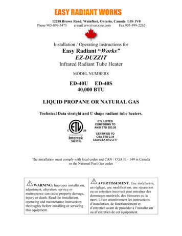
INSTALL THE SOLAR COLLECTORSOrientationSolar collectors are usually placed facing due South and at a tilt from the horizontal equal to the latitude 10degrees for balanced solar energy reception throughout the year. It is important to understand that significantdeviations from this so called “ideal” may be completely acceptable. Deviations in direction of up to 45 degrees may have less than 10% reduction in overall performance. This deviation is not enough to justify the costand heat loss of an unsightly mounting rack. Deviations to the east will favor morning performance and deviations to the west will favor afternoon performance. Deviations in tilt can also be acceptable. A lower angle willfavor summertime performance while a higher angle will favor winter performance. A tilt angle of 45 degrees ormore will usually shed snow automatically. Note that the compass does not point to due South. It is necessaryto add a “compass correction factor” of up to 17 degrees on the East coast of the United States and subtract up to15 degrees on the West coast to the compass reading to find “True” South. To get the correction factor for yourlocation, you can consult an “isogonic” chart, ask Radiantec Company or ask a local aircraft pilot.THE SOLAR COLLECTORThe solar collector is a shallow aluminum box with a tempered glass cover sheet. Typical nominal dimensions are4 ft x 8 ft x 4 in and the weight is about 125 pounds. Collectors are oriented towards the sun and when the solarenergy enters the collectors it strikes the black absorber plates and is turned into heat which is carried away bycopper tubes. A water-based antifreeze solution flows into the bottom of the collector on one side and comes outthe top on the other side after being heated by the sun.S1 Sensorhot fluid outsolderedconnectionscapped endinternalheaderscapped endcold fluid inThree solar collectors are connected to each other so that they formone large solar collector array. The collectors have “internal headers”which go across the top and bottom and have outlets on the sides.When the collectors are connected, the headers of each solar collectorare soldered to the headers of the others.3
HOW A SOLAR COLLECTOR IS CONSTRUCTEDSAFETY1. Hard hats - The worksite is a hard hat area while work is being done on the roof. There are a number of hazards, and tools or other materials could be dropped accidentally. Rope off the area beneath the roof and considerposting a sign saying that the area is a hard hat area. Keep onlookers at a safe distance.2. Do not work underneath an unsecured solar panel.3. Gloves - Solar panels get hot when bright sunlight is shining upon them and nothing is taking away the heat(stagnation). Wear gloves. Avoid working with solar panels in the middle of the day. Cover the panels with partof the shipping carton or with a tarpaulin.4. Sunglasses - Wear sunglasses when working with solar panels on sunny days. The glare reflecting from solarpanels in bright light is uncomfortable and distracting to the point of causing a safety problem. Workmen whodo not wear sunglasses are likely to go home early with a headache.5. Sign Crane - It can be economical to rent a crane and operator from a local sign contractor. Use ofa crane allows workmen to stay off of the roofing material. A crane could mount all solar panels for a typicalresidence in less than one hour.4
6. Scaffold - Erect a proper and safe scaffold. It is safer and will save many trips up and down the ladder.7. Tool Belt - Use a proper tool belt — it will also save many trips up and down and leave your hands free tohold onto the ladder or scaffold. Do not carry any extra tools: If you drop a screwdriver with a tempered bit ontoa solar collector with tempered glass, the glass could break immediately or it could break up to a week later.8. Safety Harness - Use a safety harness when on the roof.PLANNING1. Plan and locate the position of the panels with chalk lines so that their appearance can be visualized. Solarpanels are generally more attractive if they are placed at or below the midline of the roof area.2. The location of the panels should be approved before the work begins. Take a sheet of plywood up to the roofif it will help to visualize the finished work.3. In new construction, keep in mind that work may have to be done behind the roof to prepare a solid supportfor the solar collector legs. Do not put the collectors in a place where this work is inaccessible.4. Coordinate with the General Contractor. Make sure that he or she understands that solar panels will be placedupon the roof and that the roof must be built to the proper dimensions. Building insulation should not be installed in the solar work area until the solar work is roughed in and pressure tested.5. Snap another chalk line in the place where holes will be drilled for the collector mounts. Hold the line tightenough that it does not dip in the middle.6. Start in the middle of the roof and work outward. That way, you can be certain that the work will be centeredon the roof.7. Measure twice before drilling holes in importantlocations.8. Anticipate and plan for everything that needs to bedone before starting work. Read the entire manual before starting. In particular, note the following:a. Secure Attachments - Do not just lag the solarpanels to the plywood sheathing; it is not acceptable. The lag bolts must be drilled directly intothe rafters, or something else solid. Blocking canbe used to transmit the solar collector loads to therafters and provide something solid to screw the lagbolts into. Mounts provided by Radiantec can slidealong the top and bottom edges of the solar collector so that mounts can be installed directly into therafters.5
b. Compatible Materials - Whenever possible, use mounting hardware that is supplied by the solarcollector manufacturer. It is essential to avoid the use of different kinds of metals when fastening to thesolar collectors. When different kinds of metals are used, the metal that is more stable will corrode themetal that is less stable. Use stainless steel fasteners, which are especially resistant to corrosion, or usecomponents that are all made of the same material.c. Even Flow - For even flow, the solar fluid will flow into one side of the solar array at the bottom, andcome out on the other side at the top (called reverse return). The “C” type fluid return where the fluidcomes out on the same side of the collector array that it went in is only acceptable for no more than threesolar collectors. Be sure that there is an efficient way to run, support, and insulate the supply and returnpipes. Minimize exterior piping as it is inefficient and expensive to insulate.d. Expansion - Plan for expansion and contraction of the header pipes within the solar panel. Solar collector temperatures could vary between the coldest expected outdoor temperature, and the stagnationtemperature of the collector in full sun. This temperature difference could be up to 300 degrees F.e. Sensor Wire – An 18-gauge thermostat-type wire is needed for the solar collector sensor. It should bepositioned at this time and run down to the mechanical room. The sensor will be placed between the lasttwo solar panels at the outlet. Seal the roof penetration with silicone. Use shielded wire if there is a potential for radio interference (police stations, etc.).Prepare the Solar Panels for Mounting - Attach the mounting brackets to the panel. Attach the mountsso that the solar panels are held about 1” off the roof in order to prevent moisture from damaging theroofing materials.Bring the Solar Panels to the Roof and Mount - With planning and proper equipment, it is possible to dothis work without stepping on the roof.When the panel is on the roof, you or your contractor will first assemble any plumbing connections thatneed to be made. Do not solder the connections at this time. Drill a pilot hole for the collector mountwith reference to the earlier made chalk line, then insert a screwdriver through the hole in the mount andthen into the pilot hole. This will temporarily secure the panel in place and prevent the plumbing connection from becoming undone.When ready, apply a silicone-based sealant to the pilot hole and put a lag bolt in, but do not tighten it allthe way. When the lag bolts are inserted, the silicone sealant will expand under the pressure and fill anycracks or voids where water might leak in. It may be necessary to lift the solar panels a little bit in orderto retrieve the lifting sling, if used, or to make the plumbing connections. Tighten the lag bolts completelywhen this work is done.The copper connections, top and bottom, may be soldered as each panel is mounted, or they can be donefor all panels at the same time if the work will not be delayed too long (not overnight). Solder the connections using standard, no lead solder. Do not use 95/5, or silver solder and do not braise it. This is notnecessary and the excess heat will damage seals and insulation within the panel. The person who does thiswork should be skilled.6
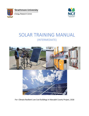
STANDARD MOUNTING (AE-MH)1. The AE-MH (standard) hardware kit allows for flexibilityin collector elevation angle and also stands the solar paneloff of the roof about 1” for moisture protection.The hardware kit has two components. The “AE clips” slipinto a track that runs continuously along the edge of thesolar panel frame. The exact position of the “AE clip” canbe variable in order to locate a rafter or other solid material,but the two clips should be located within 6-12” from theend of the solar panel. A locking bolt is available to securethe position of the “AE clip”.2. The front AE-Clips are attached to the front “Triangle Roof Mounting Brackets” with 3/8” x 1-3/4” SS bolts asshown in Figure 5.3. If an angle adjustment is not necessary, the rear mounting is the same as for the front. If an angle adjustmentis required, the rear AE-Clips are attached to the rear “Triangle Roof Mounting Brackets” via the “Tilt MountingStruts”, using a 3/8” x 1-3/4” SS bolt at the bottom and a 3/8” x 4” SS bolt at the top of each strut.Calculate the Length of Mounting Strut Required - Refer to the Appendix to calculate a strut length that willresult in the desired collector elevation angle.Pressure Test - Pressure test your work as you go, particularly with larger solar arrays. That way, if you have aproblem, you will know where it is and how to correct it. Do not pressure test with the expansion tank in place.7
THE SOLAR MECHANICAL PACKAGEGeneral - The “Solar Mechanical Package” contains all the components that are needed for the proper functioning of a closed loop, hydronic heating system. It is similar in content and function to a standard boiler system,but there are important differences.The SMP will contain at a minimum: Fill and drain valves, isolation valves, an air eliminator, an expansion tank,a pressure relief valve, a pump and a one-way check valve.When the construction of the solar loop is complete, there will be ways to: Fill the system. Drain the system. (with little or no mess) Flush the system. Back flush the system if needed. Get all of the air out, and keep it out. Work on nearly anything mechanical without draining the system. Prevent reverse thermo siphoning at night. Read the system pressure. Relieve expansion and contraction of the working fluid. Mount the pump in its proper location and orientation. Relieve pressure on the solar panels under abnormal conditions.The SMP is designed to address these issues. The components of the SMP are put together and shipped in theproper arrangement, and that is important. Of particular importance is the location of the pressure relief valve.There must be no valve, or combination of valves, which if closed would isolate the pressure relief valvefrom the solar panels. Failure to obey this fundamental rule of mechanics could cause expensive damage to thepanels or to a heat exchanger and could even cause a safety problem.Isolation Valves - If the solar energy system needs attention in the future, it will probably be in the SMP because this is where most moving parts and threaded fittings are located. Isolation valves are designed into theSMP so that work can be done on the SMP without draining the entire system. Do not add extra valves to thesystem without making sure that they will not cause problems. If you do add a valve somewhere, label its properposition.Mechanical Room - The SMP should be located in a mechanical room inside the building which will lower theperception of pumping noise (which is minor) and discourage tampering. It will protect against freezing (if itwas located in a garage, for example), conserve heating energy and eliminate nuisance heat production duringthe cooling season.Workmanship - The plumbing work must be careful and professional for many good reasons:1. An antifreeze solution is less viscous than water, and it will leak in places where water will not.2. A small leak will not repair itself by corrosion.3. A water makeup valve is not desirable because it would dilute the antifreeze solution without beingnoticed and subject the system to expensive freezing damage.8
INSTALLING THE SOLAR MECHANICAL PACKAGEREMOVE THE SOLAR MECHANICALPACKAGE FROM THE SHIPPING CRATERemove the SMP from theshipping crate.Cut the tubing where indicated and attach elbowfittings (not supplied).Solder the elbow fittingsand attach the pump.Attach the SMP to the wall and/or hangfrom the ceiling using supplied threadedrod hangers (3/8” threaded rod availablein hardware stores and plumbing supplystores).Add warning labels to the fill and drainvalves; plumb pressure relief valve to a safeplace. The warning label should read:DANGER – DO NOT OPEN THIS VALVE.THE PIPES DO NOT CONTAIN WATER.THE SYSTEM CONTAINS AN ANTIFREEZESOLUTION AND MIGHT BE VERY HOT!!Locate these valves high and out of the reach of children and limit access to the mechanical area to adults.Attach caps and tighten very snugly with a wrench (more than hand tight) to discourage tampering.9
INSTALL THE SOLAR SUPPLEMENTS MANIFOLD (if used)The solar supplements manifold is how various supplementary solar applications can beadded, such as underfloor radiant heating, long term passive heat storage, solar gardeningapplications, snow melting, pool heating and other uses for the solar energy.Use threaded rod hangers to support themanifold and provide clearance for pipeinsulation.Note: Locate this manifold at least 18” belowthe SMP to prevent excess heat from reachingany plastic tubing attached to this manifold.Remove the pressure testing equipmentafter testing supplemental uses10
RUN THE TUBING BETWEENTHE SOLAR PANELS ANDOTHER COMPONENTSUse ¾” copper tubing, type L. No substitutions are acceptable here. (except that a larger size tubing can be used iffuture expansion of the system is contemplated).SOLAR PANELSSensor – S1SolarStorage TankPlumbingMechanicalPackageSensor – S2Solar SupplementManifoldsFrom Underfloor HeatingGarden, Driveway, Sidewalk, Pool, etc.To Underfloor HeatingGarden, Driveway, Sidewalk, Pool, etc.Note: Plan to avoid over heating atplastic fittings. The solar collectorantifreeze loop can get very hot if it isonly making domestic hot water. Makesure that heat cannot conduct to plasticfittings or other components that arenot rated for high heat. The tubing thatconnects to the solar domestic tank canget very hot. Provide 18 inches of uninsulated vertical separation between thesolar tubing and any plastic connectionsat the supplements manifold.11
Roof Decketrate the roof with thewing detail.This workuld be quiet, efficientpermanent.Roof Penetration DetailSilicone RubberSealPipe InsulationThe roof can be penetrated withthis detail or with a boot. Seal withsilicone sealant, top and bottomand sides.BlockingPVC PipeFigure 8The work will be quiet and efficient if the tubing is insulated at the points of attachment first, and then fastenedsecurely to the framework of the structure. Find an 8-10 inch piece of 2” PVC or ABS. Run the tubing in themiddle and stuff fiberglass all around it. Compact until quite tight. Then secure the PVC firmly to a framingmember with two stainless steel clamps and screws or nails.Use the same technique to support tubing on long runs within the building.Do not forget the sensor wires. Attach sensor wires to the outside of the insulation to eliminatethermal degradation (See diagram in controller section).Insulation - Insulate the solar loop for efficiency, sound reduction, safety and avoidance of nuisance heat during the summer. Insulate after pressure testing and after initial startup. Insulation must have at least ¾” wallthickness and be rated for high temperatures (at least 275 degrees F). Exterior insulation must be resistant toUV radiation and moisture.Below Grade – An insulation box can be made of extruded polystyrene, which is resistant to moisture.The box can be foamed with urethane. Place 12” below grade.PRESSURE TESTThe fully assembled work should now be pressure tested at 100 psi.No loss of pressure at all is acceptable; however variations of up to5 psi can occur from solar energy striking the collectors. Do notconnect the expansion tank until after the pressure test. Verifyoperation of the pressure relief valve at 75 psi.12
ELECTRICALCONTROLLERThe Radiantec SH-08 solar heating controller turns the pump on and off according to the availability of solarenergy. Please refer to the “Owner’s Manual” for more details about its function. The experienced installershould note that there are important differences between the Radiantec SH-08 and other solar controllers.For example, the sensor locations are different.SOLAR PANELSOperates the Solar Circulating Pump — The SH-08 solarcontroller sends controlled 110v electrical power to the solar circulating pump so that the heat transfer solution (theantifreeze solution) will circulate from the solar collectorsto the domestic water heater heat exchangers and then backto the solar panels to be reheated. There are two electricaltemperature sensors (S1 and S2). S1 is placed where it willread the temperature of the fluid coming out of the solarcollectors and S2 is placed where it will read the temperature going in (See diagram).The controller compares the S1 temperatureto the S2 temperature of the pipe coming outof the tank heat exchanger (which will be thesame as the temperature of the fluid goinginto the collector). This logic is more accurateand compatible with proportional control.If there are more than one heat storage locations (as would be the case with solar systemswith more than one use for the solar energy),the S2 or storage sensor is placed where theflow from the various heat exchangers join toreturn to the solar collectors.Sensor – S1SolarStorage TankPlumbingMechanicalPackageSensor – S2Solar SupplementManifoldsFrom Underfloor HeatingGarden, Driveway, Sidewalk, Pool, etc.To Underfloor HeatingGarden, Driveway, Sidewalk, Pool, etc.If S1 is greater than S2, the pump comes on and fluid circulation begins between the solar collectors and thetank heat exchanger. When the temperature difference is small, the variable speed pump runs slowly; when thetemperature difference is greater the pump runs faster. The variable control feature has many benefits includingimproved low sun performance, less control cycling and conservation of electrical energy at the pump.13
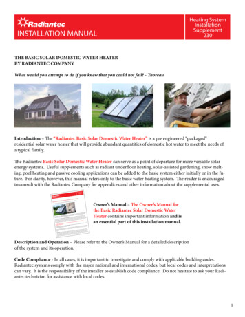
insullationfoilsensorThe placement and insulation of the temperature sensors is a very important. Performance can suffer by 20% or more if thesensors are not installed properly.The S1 sensor (the solar collector sensor) is placed betweenthe last two solar collectors in the array at the point wherethe warmed solar fluid is coming out of the collectors. Withthis placement, the sensor has a solar collector on eitherside of it and can read the collector temperature more accurately when the system is in the “off ” condition.Over temperature protection – The SH-08 controls overtemperature in an improved manner. Whenever the temperature at S1 (coming out of the solar collectors) is greaterthan a selectable temperature (default is 250 degrees F), theheat dump is activated.The solar heat dump is a small solenoid type valve that sends a small 1/4” stream of water down the drain. Theeffect is to slowly and gently cool down the entire solar energy system without consuming very much water. Thevolume of a typical heat dump is only about ten gallons and it tends to occur twice per day if the structure is notoccupied and once per day or not at all if the building is occupied. Operation of the heat dump will not compromise a septic system because if it’s low volume and high temperature which facilitates bacterial action.POTABLE SIDE PLUMBINGThe potable portion of the system consists of the solar storage tank, the 24v heat dump valve and the anti-scalding valve. The temperature of the water within the solar storage tank will be highly variable and might be veryhot. Do not send scalding water to faucets and other fixtures!! The 120 gallon solar storage tank can rangein temperature from 60 to 180 . Be sure to plan for expansion or contraction of the water in the tank. Thepreferred method is to allow for a small amount of back flow up the supply inlet. However, if a check valve orbackflow preventer is installed, a substantial expansion tank is called for. Be sure to plumb the temperature andpressure relief valves to safe location. A weeping temperature and pressure relief valves can cause serious corrosion damage to the tank.14
INITIAL START UPDo not begin the start up unless you are sure that the system is free ofleaks at 100 psi. Add the expansion tank and set for 10 psi.The system is first flushed with fresh water to remove any dirt and acid remaining from the soldering work. Usetwo garden-type hoses, one with two female ends (a washing machine-type hose can be used).Attach one hose with two female ends to a faucet at one end and to the “fill valve” of the system at the other end.Attach the other hose to the “drain valve” of the system and direct the other end outside.Cover at least half of the area of the solar panels to prevent dangerously high heat buildup. Only skilledsolar heating technicians should work on solar heating systems during sunlight hours.Ideally, the system will be complete and operating on fresh water for a period of time before the antifreeze isadded. Get all of the air out and let the system warm up. Flush the system a final time and then add a measured quantity of pure antifreeze solution such that the ending concentration will be 50% propylene glycol and50% water. Use the SH-08 controller’s manual ON switch to circulate the fluid until most of the air is eliminated. The automatic air eliminator will continue to remove dissolved air for several hours. Note that the cap mustbe loosened in order for the air eliminator to perform its function. The system pressure may fall during thistime. Automatic fill valves are to be avoided because a leak could dilute the antifreeze solution
Owner's Manual - The Owner's Manual for the Basic Radiantec Solar Domestic Water Heater contains important information and is an essential part of this installation manual. em tion t 230 1 AL n - " e l e. r s a r t t - d e sic wa d es a es. y i e ns. e r a r ies.t um e t C. n - t r h d p s t w n - o a "h e TERt o u