Transcription
Final Report: Hydrogen StorageSystem Cost AnalysisSeptember 2016Prepared By:Brian D. JamesCassidy HouchinsJennie M. Huya-KouadioDaniel A. DeSantis1
Sponsorship and AcknowledgementsThis material is based upon work supported by the Department of Energy under Award NumberDE-EE0005253. The authors wish to thank Dr. Ned Stetson and Mrs. Grace Ordaz of DOE’sOffice of Energy Efficiency and Renewable Energy (EERE), Fuel Cell Technologies Office(FCTO) for their technical and programmatic contributions and leadership.DisclaimerThis report was prepared as an account of work sponsored by an agency of the United StatesGovernment. Neither the United States Government nor any agency thereof, nor any of theiremployees, makes any warranty, express or implied, or assumes any legal liability orresponsibility for the accuracy, completeness, or usefulness of any information, apparatus,product, or process disclosed, or represents that its use would not infringe privately owned rights.Reference herein to any specific commercial product, process, or service by trade name,trademark, manufacturer, or otherwise does not necessarily constitute or imply its endorsement,recommendation, or favoring by the United States Government or any agency thereof. The viewsand opinions of authors expressed herein do not necessarily state or reflect those of the UnitedStates Government or any agency thereof.Authors Contact InformationStrategic Analysis Inc. may be contacted at:Strategic Analysis Inc.4075 Wilson Blvd, Suite 200Arlington VA 22203(703) 527-5410www.sainc.comThe authors may be contacted at:Brian D. James, BJames@sainc.com (703) 778-7114This work is licensed under http://creativecommons.org/licenses/by/4.0/. Per the license,permission to use, share, or adapt contents of this report is granted as long as attribution is givento Strategic Analysis Inc.2
ContentsTable of Figures . 4Table of Tables . 5Table of Abbreviations . 612Background, Objectives, and Tasks . 71.1Project Objectives . 71.2Tasks. 71.2.1Task 1.0 Literature Review . 81.2.2Task 2.0 Review and down-select of system to be examined. 81.2.3Task 3.0 System definition and Bill of Materials . 81.2.4Task 4.0 Manufacturing process definition and DFMA cost estimation . 81.2.5Task 5.0 Reporting . 9Analyses . 92.1Cost Analysis Methodology . 92.2Physical Storage Cost Analysis . 122.2.1Type IV 350 bar Compressed Natural Gas (CNG) Pressure Vessel Validation . 122.2.2Type IV 350 bar H2 Pressure Vessel Analysis. 152.2.3Type IV 700 bar H2 Pressure Vessel Analysis. 162.2.4Compressed H2 Component and Process Analyses . 202.3Materials-Based Storage Cost Analysis . 322.3.1Sorbent System Cost Analysis . 322.3.2Reversible Metal Hydride—Alane . 382.3.3Hawaii Hydrogen Carriers . 412.3.4Spent Fuel Recycle Cost Analysis . 412.4Electrochemical Hydrogen Compression . 453Continuation of Project . 484References Cited . 495Appendix: Project Publications and Presentations . 513
Table of FiguresFigure 1: Generic process flow diagram for Type IV compressed gas storage. Steps in blackindicate processes used at high volume manufacturing. Steps in gray indicate alternative formingprocesses that may be selected at low volume as appropriate to achieve a lower cost. 13Figure 2: Cost breakdown for modeled 275 L 250 bar type IV CNG pressure vessels at multipleproduction volumes. . 15Figure 3: Cost breakdown for modeled Type IV 350 bar H2 storage systems at multipleproduction volumes. . 16Figure 4: Cost breakdown for type IV 700 bar H2 single tank storage systems with 5.6 kg usableH2 and aspect ratio of 3. . 19Figure 5: Comparison of LP fitting quoted prices with estimated cost. . 21Figure 6: Conceptual design of integrated in-tank valve for 700 bar H2 pressure vessels. . 22Figure 7: Graph showing price quotations compared to DFMA analysis of CNG integrated tankvalves. . 23Figure 8: Conceptual integrated regulator schematic combining six low-pressure components. 24Figure 9: Impact of winding speed on cost . 26Figure 10: Comparison of material and manufacturing costs as a function of winding speed forpre-preg at multiple markups. Gray dashed lines are cost curves for pre-preg at the indicatedmarkup (e.g. the upper curve has a 12% markup applied; the next curve has a 10% markup, etc.).The red dashed line marks the cost for wet winding at 26 m/min. The analysis is based on a 1.6%COVmanufacturing for pre-preg and 3.3% COVmanufacturing for wet winding. . 27Figure 11: A. Process flow diagram and B. cost breakdown for carbon fiber manufacture. . 28Figure 12 - PFD for E-glass fiber manufacturing . 29Figure 13: Cost breakdown for E-glass fiber manufacture at 50,000 MT per year productionvolume. 30Figure 14: Manufacturing process flow for vacuum infusion. . 30Figure 15: Single variable sensitivity analysis of the Materia vacuum infiltration process for asingle 147 L tank with 5.6 kg usable H2 produced at 500,000 systems per year. . 32Figure 16: HexCell system schematic. 34Figure 17: Updated MATI system diagram showing alternative heating configuration andintegration of components. 36Figure 18: Alane storage system design. . 39Figure 19: Pre-processing steps for alane recycle. 41Figure 20: Simplified process flow diagram for batch regeneration of alane usingdimethylethylamine based on analysis in [16]. . 41Figure 21: Block flow diagram for hydrazine-based ammonia borane recycle. . 44Figure 22: Process flow diagram for hydrazine synthesis from benzophenone. . 44Figure 23: SA EHC cell design featuring individual components with the materials andmanufacturing process used in the DFMA model. . 474
Table of TablesTable 1: Standard DFMA inputs . 12Table 2: Comparison of CNG and H2 pressure vessel nominal system parameters . 13Table 3: Comparison of average commercial natural gas system parameters and cost with model. 14Table 4: Comparison of key cost and processing assumptions used in 2013 and 2015 for bulk 700bar Type IV compressed hydrogen storage system. . 17Table 5: Comparison of Type IV 700 bar H2 storage system costs at 500k systems/year for asingle 147 L tank configuration with 5.6 kg usable H2 and length to diameter ratio of 3. . 19Table 6: Bill of materials for the Provisional 2016 type IV 700 bar system cost status. . 20Table 7: Bill of materials for type IV 700 bar H2 storage systems balance of plant at multipleproduction volumes and for single and two tank configurations. . 25Table 8: HexCell Bill of Materials. 35Table 9: MATI Bill of Materials. . 37Table 10: Alane storage system bill of materials. . 39Table 11: Process assumptions for reactor A. . 42Table 12: Process assumptions the transamination reaction, reactor ‘B’. . 42Table 13: Process assumptions for adduct distillation. . 43Table 14: Process assumptions for the decomposition reaction. . 43Table 15: Hydrazine synthesis process assumptions. . 45Table 16: EHC System cost breakdown for 1 kpsi outlet pressure. 47Table 17: EHC System cost breakdown for 15 kpsi outlet pressure. 485
Table of SASRNLT-PRDAnnual Merit Review (meeting)Argonne National LaboratoryCapital CostCarbon FiberComposite Overwrapped Pressure VesselCompressed Natural GasDesign for Manufacture and AssemblyDepartment of EnergyElectrochemical Hydrogen CompressionFinite Element AnalysisFuel Cell Technologies OfficeGeneral and AdministrativeHigh Density PolyethyleneHigh PressureHydrogen Storage Engineering Center of Excellencekilowatt-hoursLow PressureModular Adsorption Tank InsertMetal Organic FrameworkMetric tons, tonnes (i.e. 1,000 kg)Non-Recurring expenseNational Renewable Energy LaboratoryOak Ridge National LaboratoryPacific Northwest National LaboratoryPounds per Square InchResearch and DevelopmentReturn on InvestmentStrategic Analysis, Inc.Savannah River National LaboratoryThermal-Pressure Relief Device6
1Background, Objectives, and TasksThe Fuel Cell Technologies Office (FCTO) has identified hydrogen storage as a key enablingtechnology for advancing hydrogen and fuel cell power technologies in transportation,stationary, and portable applications. Consequently, FCTO has established targets to chart theprogress of developing and demonstrating viable hydrogen storage technologies fortransportation and stationary applications. This cost assessment project supports the overallFCTO goals by identifying the current technology system components, performance levels, andmanufacturing/assembly techniques most likely to lead to the lowest system storage cost.Furthermore, the project forecasts the cost of these systems at a variety of annual manufacturingrates to allow comparison to the overall 2017 and “Ultimate” DOE cost targets. The costbreakdown of the system components and manufacturing steps can then be used to guide futureresearch and development (R&D) decisions.The project was led by Strategic Analysis Inc. (SA) and aided by Rajesh Ahluwalia and ThanhHua from Argonne National Laboratory (ANL) and Lin Simpson at the National RenewableEnergy Laboratory (NREL). Since SA coordinated the project activities of all threeorganizations, this report includes a technical description of all project activity.This report represents a summary of contract activities and findings under SA’s five yearcontract to the US Department of Energy (Award No. DE-EE0005253) and constitutes the “FinalScientific Report” deliverable. Project publications and presentations are listed in the Appendix.1.1 Project ObjectivesThe objectives of this project were to: Identify and update the configuration and performance of a variety of hydrogen (H2)storage systems for both vehicular and stationary applications on an annual basis.Rigorously analyze the manufacturing cost of multiple H2 storage systems to reflectoptimized components for the specific application and manufacturing processes atvarious rates of production.Explore cost parameter sensitivity to gain an understanding of system cost drivers andfuture pathways to lower system cost.Document all analysis results and assumptions in a comprehensive annual report.1.2 TasksThe project was organized around five main tasks: Task 1: Literature Review Task 2: Review and down-select of systems to be examined Task 3: System definition and bill of materials Task 4: Manufacturing process definition and DFMA cost estimation Task 5: Reporting7
A brief description of each of the tasks as defined in the statement of work follows.1.2.1 Task 1.0 Literature ReviewStrategic Analysis (SA) conducted a continuous literature review throughout the project to stayapprised of the latest developments in on-board H2 storage system concepts, configurations,materials, and associated manufacturing technology. The review was more intensive during thefirst three months of the project to establish a base of information. The review included reviewsof the status of selected storage technologies as directed by DOE’s Hydrogen Storage Team andincluded the status of storage material properties and characterization, system level designs,safety analysis/testing of the storage options, schematics identifying the need for all subsystems,and balance of plant (BOP) requirements for practical operation. After the initial review, theliterature review focused on staying abreast of ongoing developments. Literature sourcesincluded journal articles, conference proceedings, DOE contractor reports, company reports,patents, and newspaper articles.1.2.2 Task 2.0 Review and down-select of system to be examinedSA down-selected specific storage methods and applications for cost analysis. Storage systemoptions analyzed were: 350 bar pressurized hydrogen gas, 700 bar pressurized hydrogen gas, andadsorbent materials. The primary application considered was H2 storage for light-duty fuel cellautomobiles.1.2.3 Task 3.0 System definition and Bill of MaterialsSA prepared system definitions corresponding to each of the systems identified in Task 2.System definitions were developed based on third-party designs and augmented by SA to theextent necessary for cost analysis. The systems were defined in flow schematics that identifiedall components of the system as well as a visual listing of relevant parameters (storage amount,mass flow, pressure, temperature, materials, etc.) System definitions were supported by systemperformance modeling calculations supplied by the DOE Storage Team and/or third-partyvendors when possible, and supplemented with Excel and/or Hysys performance modelingconducted by SA and its team members. From the system definitions, a bill of materials (BOM)was created for each system tabulating all system components and subsystems contained in thestorage systems. The BOM served as the master index of each system and was further detailedduring Task 4. The flow schematics and BOM reflect changes in the systems betweenapplications and the various annual manufacturing rates considered. The system definitions andbills of materials were reviewed with the Storage Team and industry for accuracy andcompleteness.1.2.4 Task 4.0 Manufacturing process definition and DFMA cost estimationSA conducted rigorous DFMA analysis based on 2015 (and beyond) storage technologyprojections. Estimated total storage system costs were predicted for up to five annualmanufacturing rates ranging from initial market penetration volume through high volume.Manufacturing volumes ranged from 1,000 systems per year to 500,000 systems per year. To8
accomplish this, the following analyses were conducted as part of the overall task effort:enumeration of all manufacturing/assembly/testing steps and identification of all cost andfabrication assumptions used in the cost analysis, investigation and detailed specification ofquality control equipment to ensure high yields and low costs, mathematical functions to scalesystem component costs, Tornado sensitivity analysis based on performance variations and keymanufacturing or design changes, and recommendations for a feasible path forward to reducetotal system cost. The cost analyses were based on H2 storage system measurements, from DOEor third-parties, which were previously verified. All analysis results were documented in reportsto DOE. The viewgraphs and reports were circulated to the DOE, H2 storage community, and themanufacturing community for feedback as to technical and cost realism. Project methodology,key assumptions, and results were briefed to the DOE Storage Team and at the Annual MeritReview (AMR) (plus other groups as requested by DOE). To validate the cost models, acurrently produced storage system were cost modeled and the resulting predictions comparedagainst the known factory costs. The DOE Hydrogen Storage Team facilitated the definition ofthis baseline system and obtaining the factory cost values. SA worked closely with the thirdparty vendor to validate the model and compare system costs. This task was repeated in eachbudget period.1.2.5 Task 5.0 ReportingReports and other deliverables were provided in accordance with the Federal AssistanceReporting Checklist following the instructions included therein. Clear, concise, assessable, andreferenceable reporting of the methodology, assumptions, and results was a key objective of theproject. For maximum accuracy and usefulness, the assumptions and results for the project werevetted by a wide range of individuals and groups. Reports were generated and presented at the: 2Hydrogen Storage Systems Analysis Working Group (SSAWG) MeetingsUSCAR and Fuel Hydrogen Storage Technical Team MeetingsDOE Hydrogen Program Merit Review and Peer Evaluation (AMR) meetingAnalysesThe analyses conducted during this contract are described in the following section. Cost analysisof emerging technologies is inherently an iterative process as the technology, designs, andperformance is rapidly changing. Consequently, some of the analyses in this report are marked aspreliminary to denote their interim status as of the report date, due to either on-going areas ofinvestigation or a shifting of DOE priorities. However, these preliminary analyses havesignificant value and are included to provide both status reporting and identification of costdrivers and manufacturing requirements.2.1 Cost Analysis MethodologySA uses a Design for Manufacture and Assembly (DFMA ) cost methodology approach toproject the cost to manufacture hydrogen storage systems. DFMA is a process-based cost9
analysis methodology which projects material and manufacturing cost of the complete system bymodeling specific manufacturing steps. Consequently, the first steps in performing cost analysisare to define the system design and the specific manufacturing and assembly steps required toachieve the specified design. Once the system and manufacturing/assembly steps are specified,the material inputs, capital equipment costs, and operating expenses are computed. The estimatedcost is the sum of the material, manufacturing, and assembly costs. Material costs are based onthe actual gross material cost consumed in each step (i.e. including scrap or other wastage).Manufacturing and assembly costs are defined as the product of machine rate (in /min) andprocessing time (i.e. minutes to conduct that particular operation). Machine rate is defined as:ℎ ! "#.Thus machine rate varies with annual production rate since Annual Capital Repayment is anannual fixed charge: the higher the machine utilization, the lower the machine rate. AdditionallyAnnual Capital Repayment reflects the repayment of principle (i.e. repayment of the purchaseprice of the processing equipment), loan or return on investment (ROI) payments (i.e. paymentof interest on the equipment loan or equivalent ROI to the business for providing the capital),and taxes (i.e. an increase in payment to reflect that interest and ROI payments are paid withafter-tax dollars). Annual operating payments include variable costs for labor, maintenance,repair, and utilities. Material and manufacturing costs are tabulated for each step in theproduction process and then summed to achieve a system cost projection.Typically, SA projects the cost (not the price) of the system to the final system integrator (i.e. thecompany that sells the fully assembled storage system. Consequently, the projected cost onlyreports the materials/manufacturing/assembly costs and does not include markup for profit, onetime costs such as non-recurring engineering (NRE) costs, general and administrative (G&A)expenses, warranties, or advertising; however, components that are assumed to be purchased forthe system (e.g. valves, gas lines, etc.) include vendor markup. (This reflects that fact that the“price” of the purchases component is a “cost” to the final system integrator.) Standard valuesare used in the analyses for interest rates, labor rates, etc. to provide a common, transparentframework. These are summarized in10
Table 1.Throughout the analysis, cost is normalized on a /kWh to allow comparison with DOE targetsand as a metric which refers to total available onboard fuel storage. The energy content ofhydrogen was taken on a lower heating value (LHV) basis, i.e. the LHV of hydrogen is assumedto be 33.3 kWh/kgH2.11
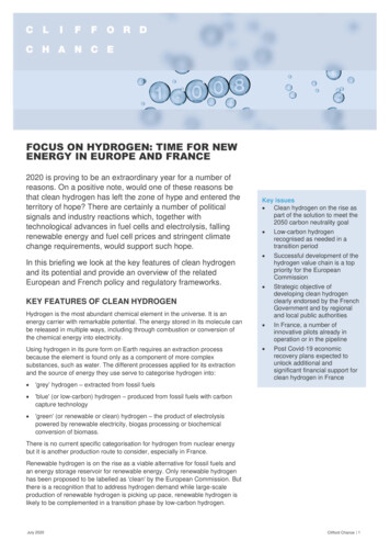
Table 1: Standard DFMA inputsPossible Runtime per DayWork Days/YearPossible Annual Runtime per LineDefault Machine LifetimeDiscount RateCorporate Income Tax RateAverage Equipment Installation FactorAverage Maint./Spare Parts (% of CC per year)Average Misc. Expenses (% of CC per year)Electric Utility CostAverage Labor Rate (inclusive of direct labor, benefits,employer r /kWh /hrValues142403,3601510%40%1.410%7% 0.07 422.2 Physical Storage Cost AnalysisPhysical storage approaches include ambient temperature compressed gas, cryo-compressed gas,and cryogenic storage. During this contract, the cost of ambient temperature hydrogen storagewas analyzed.2.2.1 Type IV 350 bar Compressed Natural Gas (CNG) Pressure Vessel ValidationA validation study of the H2 pressure vessel cost model was completed in the first year byadapting the previously SA developed cost model to represent a CNG pressure vessel and thencomparing the projected results to actual vendor high production CNG quotes. CNG pressurevessels are manufactured in a very similar way to compressed H2 Type IV tanks: a polymer lineroverwrapped by continuous carbon fiber filament. For this comparison, a 270 liter (internal watervolume) CNG tank (sized for light duty trucks) was selected for modeling based on discussionswith CNG industry professionals who suggested that such a tank is currently produced at(relatively) high manufacturing rates. While CNG tanks for light duty vehicles (120 liter watervolume) are produced at higher manufacturing rates (5,000 systems/year) by StructuralComposite Industries (SCI)/Worthington Cylinders, the vessels are Type III tanks (metal lined,waist wrapped) rather than the Type IV tanks assumed for current H2 storage pressure vessels.Consequently, the SCI tanks were rejected as the CNG validation basis. Table 2 compares keyparameters for CNG and H2 pressure vessels.The general manufacturing process used for composite overwrapped pressure vessel gas storagesystems (CNG, 350 and 700 bar H2 systems) is shown in Figure 1.12
Table 2: Comparison of CNG and H2 pressure vessel nominal system parametersPressureProd. RateStructural FiberFiberglassLiner MaterialLiner Formation MethodLiner ,000’sT-700 carbon fiberOuter LayerHDPERoto-mold0.4H210,0001,000-500,000T-700 carbon fiberNoneHDPEBlow mold0.5Figure 1: Generic process flow diagram for Type IV compressed gas storage. Steps in blackindicate processes used at high volume manufacturing. Steps in gray indicate alternative formingprocesses that may be selected at low volume as appropriate to achieve a lower cost.Argonne National Lab (ANL) used the ABAQUSTM finite element analysis (FEA) modeling toolto identify material masses and dimensions which were used as input values for SA’s DFMApressure vessel cost model. Results from the cost analysis were then marked up to allow directcomparison to price quotations provided by CNG tank manufacturers (Quantum Technologies,3M, and Hexagon Lincoln) to validate the cost modeling approach. The final analysis resultsshown in Table 3 compare price quotations provided by manufacturers with the correspondingassumed markup schemes to allow assessment of the DFMA cost results. SA’s results are ingood agreement with Quantum and 3M quotations; however, Hexagon Lincoln prices are 15%lower than SA modeled prices. This difference is attributed to Hexagon Lincoln’s higher actualtotal tank production volume compared to SA modeled production volume for a single vesselsize: Hexagon Lincoln has lower costs because they have higher machine utilization due to13
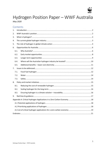
producing multiple sizes of vessels, not just the DFMA modeled size). Additionally, HexagonLincoln’s interior tank volume is slightly lower than the other manufacturers in part due to theiraddition of fiberglass to both the outer tank wrapping (for abrasion and chemical resistance) andto the inner fiber wrapping (for impact resistance). Quantum and 3M restrict fiberglass to theoutside of the tank only, thereby providing a higher internal volume for the same outer tankdimensions. During this analysis, it was noted that the DFMA cost projection is quite sensitive toproduction rate. Thus, minor assumption differences in annual production rate can lead tosignificant changes in projected cost. Figure 2 shows the cost breakdown of modeled CNG tanksat several production volumes.Table 3: Comparison of average commercial natural gas system parameters and cost with model.2Annual ProductionInterior VolumeTank MassTank Cost3Manufacturers Markup4Installer Markup4Tank PriceUnitsunits/yearLkg %% Commercial System11,00026870.82,58715103,272Modeled System1,00027567.72,85215103,6071Values are the average from vendors polledCommercial production volumes are estimated3Estimated from assumed markups for commercial systems4Estimated for manufacturer and installer214
Figure 2: Cost breakdown for modeled 275 L 250 bar type IV CNG pressure vessels at multipleproduction volumes.2.2.2 Type IV 350 bar H2 Pressure Vessel AnalysisThe validated CNG cost model was used to analyze the costs of 350 bar Type IV H2 storagesystems. The manufacturing process flow is the same as shown in Figure 1 with differences insystem size, pressure, and production volume. Figure 3 shows a cost breakdown of 350 bar typeIV H2 storage systems. In contrast to the CNG system, H2 storage system costs are dominated bybalance of plant (BOP) and composite at all volumes. Due to the higher pressures beingconsidered for H2 storage (350 bar and 700 bar vs. 250 bar for CNG), significantly more carbonfiber composite is required to achieve the design pressure. For 250 bar CNG tanks, around 50 kgof composite is required for a 275 L pressure vessel, while 62 kg of composite is required for a245 L H2 pressure vessel at 350 bar [1]. It is also noteworthy that the production volumesanalyzed for the H2 storage begin at the upper range of the CNG production volume (10,000systems per year).15
35MPa Com
SA down-selected specific storage methods and applications for cost analysis. Storage system options analyzed were: 350 bar pressurized hydrogen gas, 700 bar pressurized hydrogen gas, and adsorbent materials. The primary application considered was H2 storage for light-duty fuel cell automobiles.