Transcription
Alpha-Bio Tec DrillsScientific Overview
IndexChapter 1 – Advanced Drill Line OverviewIntroductionKey design features44-9Alpha-Bio Tec Advanced Drill line10-12Summary and conclusions13-15Chapter 2 – Alpha Bio Tec Revised Drill Protocol:2Bone Classification and Implant Osteotomy20-21Revised Drill Protocols22-27
Alpha-Bio TecAdvanced DrillLine Overview3
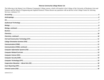
Alpha-Bio Tec Introduces a newand advanced drill lineIn this document, Alpha-Bio Tec scientifically demonstrates best possible design supported by design features thatreduce heat and enhance bone preservationIntroductionWhen designing dental drills, all characteristics and propertiesshould be adjusted to create minimal temperature rise duringthe drilling process. One of the main causes of failure indental implant osseointegration is the increase of bonetemperature above 47 C during bone drilling resulting inirreversible osteonecrosis [1,2] . Having a necrotic area surroundingthe implant reduces the efficiency of the osseointegrationprocess, leading to loss of rigid fixation. The thermal damageat the drilling site inhibits the regenerative response inbone healing, damaging the osseointegration process andpotentially resulting in the implant’s lack of secondary stability.Drill design plays a significant role in controlling the heatgenerated during drilling and several design features should beconsidered. A combination between surgical tools and optimalimplant site preparation will result in enhanced osseointegrationand reduced failure rate.Key Design Features1Use of CoolantThe use of coolant is the most influential factor on boneheating which significantly decreases the temperatureinduced during the drilling process [3-7] . Cooling is suppliedby one of two methods - internal or external. In an internalcooling system, the coolant passes through an internaldrill hole and exits through the drill flutes. The coolingmechanism is a combination of heat transfer betweendrill, coolant and bone. In addition, the coolant provideslubrication and irrigation. Lubrication reduces the frictionduring drilling, thereby reducing heat. Irrigation effectivelyremoves chips and debris produced during the drillingprocess, prevents clogging of flutes and allows boneextraction which reduces the heat. In an external coolingsystem, the coolant is induced from an external nozzleonto the drill’s external surface reducing heat throughconvection mostly on the exposed drill portion and theupper cortical bone. When examining the various effects ofthese two methods, we first recognized that both methodssignificantly reduce bone temperature during drilling.Matthews and Hirsch [4] studied the coolant effect whendrilling through human cortical bone and found that coolingis highly effective in reducing the maximum temperaturereceived. They used water at room temperature withflow rates of 300, 500 and 1000 ml per minute. They alsoconcluded that increasing the irrigation rate reduces bonetemperature developed during drilling and further, that thetemperature never increases above 50 C at the irrigationrate of 500 ml/min or above (Figure 1).4
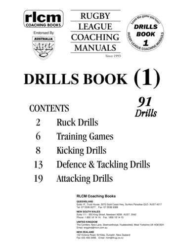
and Hirsch [4] studied the coolant effect when drilling through human cortical bone and foundng is highly effective in reducing the maximum temperature received. They used water at roomure with flow rates of 300, 500 and 1000 ml per minute. They also concluded that increasing therate reduces bone temperature developed during drilling and further, that the temperature neverabove 50 C at the irrigation rate of 500 ml/min or above (Figure 1).2Heating generation overviewThere are several drilling parameters considered to besignificant for controlling heat generation during drilling,including spindle speed, feed rate, drilling sequence anddrilling depth. Understanding the effect of each parameterwill enable better control of the temperature generated andwill avoid necrosis during drilling [11-16] .Figure 1 – Effect of cooling rates on average maximum corticaltemperatures recorded at specific distances from the drill [4]Fig 1Lee et al. [11] studied the effect of spindle speed, feed rateand depth of drilling on the temperature distribution duringthe drilling of cortical bovine femur and found that themaximum temperature increases with increasing spindlespeed and independently decreases with the increasingfeed rate (Figure 2).with increasing spindle speed and independently decreases with the increasing feed rate (Figure 2). TEffectcooling ratesofoninternallyaverage maximumcorticalet al [8] investigatedtheofperformancecooled stepdrill duringtheof porcinealso showedthat asthedrillingdrilling depthincreases, the maximum temperature increases (Figure 3).recordedat specificdistancesd found that the temperaturescooling systemproducesbone temperaturessignificantly below the thresholdal osteonecrosis. from the drill [4]mparing internal and external cooling systems, the internal cooling system is more efficient inile the externalAugustincooling systemis more efficienton the surface[6, 9]. The internal cooling systemet al. [8] investigatedthe performanceof internallyess increases ascooledthe depthstep increases.drill during the drilling of porcine femora andfound that the cooling system produces bone temperaturesl [10] studied bovinemandibleduring fordrillingwithosteonecrosis.coolant and observed that more heatsignificantlybelowheatingthe thresholdthermaled on the surface of the drilling cavity as compared to the bottom surface. As a result, theynded external Whenirrigationas a ernal andexternalcoolingsystems,theFurther, field experienceockage of the internallumeniswheninternalirrigationcooling systems.internal irrigationcooling systemmore usingefficientin depth,while theexternal cooling system is more efficient on the surface [6,9] .The internal cooling system effectiveness increases as theing Parametersdepthand Procedureincreases. OverviewFigure 2: Thermal history for thermocouples located at radii locations of 0.5 mm (TC3), 0.81 mm (TC2),several drillingSenerparametersconsideredbe significantcontrollingheat generation duringet al. [10] studiedbovinetomandibleheatingforduringdrillingand 2.78 mm (TC1) from the center of the drilled hole; maximum drilling depth of 7 mm (Animal A) [11]cluding ingdepth.Understandingthe effect ofcoolant and observed that more heat is generated onFig 2meter will lavoidnecrosisduringthe surface of the drilling cavity as compared to the bottomThermalhistoryfor thermocouples located at radii1-16].surface. As a result, they recommended external irrigationas a sufficient cooling system during drilling. Further, fieldlocations of 0.5 mm (TC3), 0.81 mm (TC2), and 2.78mm (TC1)from the center of the drilled hole; maximum[11] studied theeffect ofshowedspindle blockagespeed, feedand depthof drilling on thetemperatureexperienceof ratethe internalirrigationdrillingdepthof 7 mm (Animal A) [11]n during the mtemperatureincreaseslumen when using internal irrigation cooling systems.Figure 3: Maximum temperature at 3 mm depth (TC3) as a function of the spindle speed forhole depths of 6 mm and2 7 mm, and for an initial temperature of 26 C [11]5Cordioli and Majzoub [12] examined bovine femurs by drilling with 1500 rpm and external irrigation,
2: Thermal historyforal.thermocoupleslocatedat radiilocations0.5 mm (TC3),In0.81mm (TC2),addition,it is recommended to interrupt the drillingLee etalso showed thatas thedrillingdepth ofincreases,78 mm (TC1) fromcenter of thedrilled (Figurehole; maximumdrilling depth of 7 mm(Animal A)procedureat [11]least every 5 s for at least 10 s and apply salinethethetemperatureincreases3).to the bone. Using this sequence will significantly decreasethe time of elevated bone temperature [14] .3Mechanical Featuresi Drill FlutesFlutes are grooves created on the drill surface for two mainfunctions (Figure 4). The first, is creation of the cuttingedge and determination of the number of cutting edges.The second, functioning as an exit path for chips and debrisFigure 3: Maximum temperature at 3 mm depth (TC3) as a function of the spindlespeed forduring the drilling process.producedhole depthsFigof36 mm and 7 mm, and for an initial temperature of 26 C [11]Maximum temperature at 3 mm depth (TC3) as afunction of the spindle speed for hole depths of 6 mm[11]and 7 mm,and forfemursan initialbytemperatureof 26 Cexaminedbovinedrilling with1500 rpmBertollo et al. [17] tested two- and three-fluted surgical drillsand concluded that a three-fluted design has superiorbendingstiffness.In furtherjzoub [12]andexternalirrigation,andstudies, Bertollo et al. [18] alsoconcluded that the cutting efficiency of a three-flutedtemperatures at 8 mm depth, as compared to 4 mm depth, regardlessof the drill diameterdesign is greater than that of the two-fluted drills. However,e of cooling. Cordioli and Majzoub [12] examined bovine femurs by drillingwhen trying to establish this theory while measuring thewith 1500 rpm and external irrigation and reached highermaximum drilling temperature of the two, no significantat 8 mmanddepthas comparedto 4maximummm depth, temperature3] examined temperaturescadaveric femurfoundthat thewithdifferences decreaseswere observedbetween two- and three-flutesof theSharawydrill diameterandthe presenceof cooling.drills. Further,additionalflutes in the design may narrowthrust force regardlessat 820 rpm.et al[14]measuredthe heat generatedfromdifferentthe channels of1225, 1667, and 2500 rpm)and found that the mean rise in the temperatureat thetheflutestimethatof act as a path for bone chipBachus et al. [13] examined cadaveric femur and found thatremoval, eventually resulting in impaired cutting efficiencyes as the drillingspeed increases.the maximumtemperature decreases with increasing axialand elevated frictional heat. Additional research is requiredthrust force at 820 rpm. Sharawy et al. [14] measured the heaton the optimal number of flutes and its effect on stability,asured heat generatedgenerationofdifferentthree implantdrill systemsandandfoundcuttinga decreasein andmaximumfromdrilling speeds(1225, 1667,efficiencyfrictional re,hen increasing the number of drills in the drilling sequence as a result of smaller bonethe drilling speedincreases.ed at each decreasesstep. Asassubstantialamountsof bone have already been removed in theences with smaller diameterdrills, the larger diameter drills are iisubjectto cut& Rakeless bone,Helix AngleAngleChacon [15] measured heat generation of three implant drillting in ommendedtointerruptthe as the angle formed by thesystems and found a decrease in maximum temperatureHelix angle of the drill is definedwhen increasing the number of drills in the drilling sequenceas a result of smaller bone volume excavated at each step.As substantial amounts of bone have already been removedin the preceding sequences with smaller diameter drills, thelarger diameter drills are subject to cut less bone, therefore,resulting in smaller temperature increases [16] .6edge of the flute with the line parallel to the drill center line(Figure 4). Rake angle is defined as the angle between thecutting edge and the plane perpendicular to the work-piece3(Figure 5).
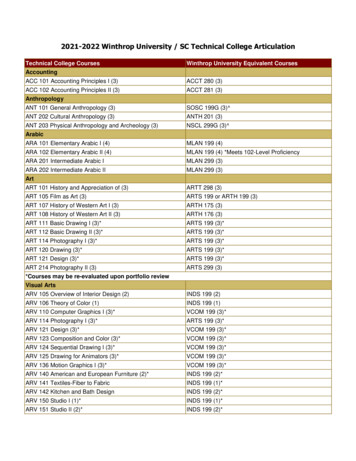
& Rake Anglerill is defined as the angle formed by the edge of the flute with the lineparallel to thee angle is defined as the angle between the cutting edge and the planeperpendicularHelix angle and rake angle are interrelated, as a larger helixangle results in a larger rake angle. The helix angle providedangle are interrelated,largerhelixstandardangle resultson thedrill asbit acanbe slow,or quick,in adependinglarger rake angle. The helixhe drill bit canupon[19]orbe slow,Motion of chipstandathe helixanglerd. quick, depending upon the helix angle [19] (FigureChipCutting toolRake faceMotion of tool(relative to work)Original surfaceFlankFluteSlow spiral(small helix angle)Shear deformationto form chipNew surfaceWorkpartCutting edge of toolStd spiral(standard helix angle)Cutting toolNegativerake angleQuick spiral(large helix angle)Relief angleFigure 4: Slow (smallFlutehelix angle),HelixStandarAngle d and quick helix [19]d in such a way that there is a compromise between the strength of thecutting edgeection through theFig 4flutes [20]. When increasing the helix angle, cuttingFigefficien5cy isSlow (small helix angle), Standard and quick helix [19]Illustration4Helix angle is defined in such a way that there is a compromisebetween the strength of the cutting edge and efficient chipejection through the flutes [20] . When increasing the helixangle, cutting efficiency is reduced, however, a higher feed rateis achieved and drill propagation reduces the drilling time.As a result, there is a clear tradeoff between these twoparameters to receive the optimal helix angle. For a surgicaldrill, the range of 12 -28 helix angle is usually suggested andrecommended by several researchers [20-24] . Increasing the rakeangle ( in Figure 5) will result in a decrease of the bone cuttingforces [21,25] . An optimum rake of 20 -30 was recommendedby Hillery and Shuaib [26] as it sufficiently clears the chips andgenerates very low thrust force.7
reduced,reduced,however,however,a highera higherfeedfeedraterateis e.AsAsa aresult,result,therethereis isa stedFora 2 -28 12 -28 helixangleangleis dedbybyseveralseveralFigure5:WikipediaFigure5: nFigureFigure5)5)willwillresultresultinina 25].AnAnoptimumrakeofof20 -30 20 -30 sitaitsufficientlysufficientlyed, however,a[21,higherfeedrate force.s a cleartradeoffbetweenthese twoparametersto receive the optimal helix angle.iv Point AngleReliefAnglehelix& Bodysurgical drill, the iiirangeof 12 -28 angle Clearanceis usually suggested and recommended by severalchers [20-24]. Increasing the rake angle (ɑ in Figure 5) will result in a decrease of the bone cutting[21, 25]. An optimumrakeof 20 -30 was recommendedby Hilleryand Shuaibas it sufficientlyPoint angle is the angle formed between the drill’s outerReliefangleis definedas the surfaceadjacentto the[26]cuttingthe chips and generates very low thrust force.ce & Clearanceglediameter just above the cutting edge and its tip (Figure 8).edge and below it when the tool is in a horizontal positionLarger point angles provide full contact of the cutting lip(Figures 5). Body clearance is defined as the surface thateefinedsurfaceadjacentto thecuttingand belowwhenthe ittoolis inthea tool is in aas followsthe surfaceadjacentto edgethe cuttingedgeitandbelowwhenwith the bone as soon as drilling begins, resulting in reducedbehind the edge and up through the drill fluteFigure5: 5:WikipediaFigureWikipedia6).(FiguresBody clearanceis definedas isthesurfaceasthatfollowsthecuttingedgeandtheon5, dandheatbehinddue tofollowsfasteractionalong edgewith lessacute tip(FigureBothreliefangle izedbonetodrillcontacture 7).Bothrelief7).anglebodyclearancereducethe eand bodyreducethe heatduegenerationdue to [28] .Point nceClearanceduringosteotomy preparation [15, 16] . Larger relief iefanglesgenerallyone to ,16].Largerreliefanglesgenerallytend duringto producea better finish aslessPointsurfaceofis theofForsurgicaldrills, researchersrecommenda pointangleangleangleformed betweenthe drill’s outerdiameter justabovethe cuttingedge and itReliefadjacenttototheReliefangleangleis ecuttingcuttingedgeedgeandandbelowbelowit itwhenwhenthethetooltoolis isinina aFigure5: Wikipedia[27][25] bsagainstthebonesurface.90 rubsagainstthe bonesurfacea betterfinishas5,oflesssurfaceof thewornflankof thethedrillagainstthe bone surface soon as drilling beghorizontal(Figuresclearanceis facesurfacefollowsbehindtheedgeand rubsresultingingenerationreducedheatdue tocutting actionacute tip fordrillsprimary stability wever,lack bodyclearance.therangeoffaster100 -130 point alonganglewithfor lessall followingelief,lackbodyclearance.l nitialdrills [28]. [19,21,24,29] .diametersRelieftendAngle& Clearanceto producea better finish as less surface of the worn flank of the drill rubs against the bone surfacetend to produce a better finish as less surface of the worn flank of the drill rubs against the bone odyclearance.clearance.For surgical drills, researchers recommend a point angle of 90 for initial drills as they create the first drangle is defined as the surface adjacent to the cutting edge and below it when the tool is in ahole [25] and the range of 100 -130 point angle for all following drills diameters [19, 21, 24, 29].ntal position (Figures 5, 6). Body clearance is defined as the surface that follows behind the edge andough the drill flute (Figure 7). Both relief angle and body clearance reduce the heat generation due toinimized bone to drill contact during osteotomy preparation [15, 16]. Larger relief angles generallyo produce a better finish as less surface of the worn flank of the drill rubs against the bone surfaceMost dental drills have relief, however, lack body clearance.a(b)(b)(a)(a)bFigure6: eDrillwithandwithoutrelief(a)Fig 6(b)(a)a and with b(b) body clearance(a)Drill bit without(b)Figure 8: Point angle6: Drill bit(a)(a) andbitwithout(b) reliefFigure 6: Drill llwith(a)without (b) reliefFigure7: odyclearanceBody ClearanceFig(Step8 Drill Bit)e) Two Phase Drill BitPoint angleReliefTwo phase drill bit has an effective design that minimizes temperature elevation due to gradual removmaterial from the drilling site [30]. Step drill may also assist in centralizing the drilling process.centralizing feature is due to the lower drill step (small diameter phase) leading the way throughSlow spiral55predrilled site.(small helix angle)Figure 7: Relief angle and body clearanceUdiljak et al [?] examined heat generation with conventional drills and step drills and received lomaximum bone drilling temperature using a step drill as compared to a conventional drill (Figure 9).Fig 7Relief angle and body clearanceFigure 7: Relief anglebody angleclearanceFigureand7: Reliefand body clearance85
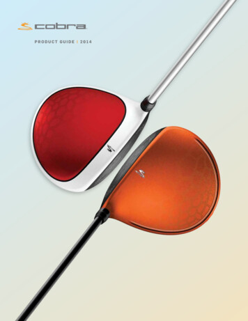
v Step Drill BitStep drill bit has an effective design that minimizes temperatureelevation due to gradual removal of material from thedrilling site [30] . Step drill may also assist in centralizing thedrilling process. The centralizing feature is due to the lowerdrill step (small diameter phase) leading the way throughthe predrilled site.Maximal bone drilling temperature, O CUdiljak et al. [30] examined heat generation with conventionaldrills and step drills and received lower maximum bonedrilling temperature using a step drill as compared to aconventional drill (Figure 9).Bubeck et al. [31] examined cadavers’ bone heat generationcomparing step drills versus sequential drilling and foundthat the maximum heat generation with step drilling andsequential drilling was not significantly different at 60 N and120 N of drilling force. However, at 80 N, a significant variableof 2.13 ºC was found between the two drilling techniques andthe time to complete (seconds) was significantly shorter forthe holes created by step drilling than by sequential drilling.50454035302520151050Step drillConventional Surgical DrillFig 9Maximal bone drilling temperature in dependence onthe drilling tool geometry according to Udiljak et al. [3 0] .9
2 Experimental MethodAlpha-Bio Tec Advanced Drill Lineat el [31] examined cadavers’ bone heat generation comparing step drills versus sequential Adrillingmeasurement system was designed to evaluateAlpha-BioTec advanced drills were designed following and that the maximumheat generationwith step drilling and sequential drilling was not significantlyheatgeneration,exerted forces (axial and torque) archheat illingt1]at examined60 N and 120comprehensiveN of drilling force.However,at 80 N, the2.13ºC variablebetweentwo drillingstabilityofABT’snew drill line (Step & Straight) ficantandthetime mentionedto complete(seconds)wassignificantlyshorterfor thewasholesthewasmaximumheatgenerationwith stepdrillingandsequentialdrillingnot significantlyisolatingthefollowingdesign parameters:by step drilling thanby sequentialdrilling.To edNand 120 N offorce.However,at Alpha-Bio80 N, theTec2.13variable betweenthetwo drillinga.Bodyclearancesystem which measures heat generation and mechanicals significant aandthe time to complete (seconds) was significantly shorterfor theb. Step drillsrakeholesangleforces (torque & axial force) exerted on the bone during theLineby sequential illing process.o Tec advanced drills were designed following a comprehensive research process. The advancedContra angle handle of the physio-dispenser was fixedtook the above mentioned parameters into consideration. To validate drill line performance,to the linear arm and the drill’s position was calibratedo Tec have designeda systemSet-upwhich measures heat generation and mechanical forces (torque &1 SystemedDrillLinetobe exactly perpendicular to the bone model surfacece) exerted on the bone during the drilling process.(Figure10) advancedLoadcell&Tourqemeteradvanced drills were designed following a comprehensive research process. Thestem Set-upConstantrotational speed of 1000 rpm was set.Lineararmthe above mentioned parameters into consideration. To validate drill line performance,Axial movement of the linear arm was set to a constantThermal Camerahavedesigneda system which measures heat generation and mechanical forces (torque &Load cell& Tourqe meterspeed creating a constant and unified penetration/Bovine bone tissue (Ribs) analog with 2 mm of organicLineararmthe bone during the drilling process.rted onretraction of the drill in/out the bone model ( feed rate)cortical bone which represent a 1200/600 Hunsfield unit boneThermal Camera - Infrared camera with 120 Hz frame rateDrilling depth was set to 11.5 mmPhysio-dispenserBovine bone tissue (Ribs) analog with 2 mm of organic cortical bone which represent a 1200/600t-upAll tests were performed without irrigation to isolate itsOpticalmeasurementsystemHunsfield unit boneeffectMiniUNIKO Physio-dispenser by Mariotti & C srlell& TourqemetersystemOpticalmeasurementDrills’ maximum temperature was measured after drillretraction from the hole and bone temperaturearmisotherm was verifiedal Camera - Infrared camera with 120 Hz frame rateDrills’ axialforces and exerted torques were continuouslybone tissue (Ribs) analog with 2 mm of organic cortical bone which representa 1200/600recordedeld unit boneDrill’s temperature performance was verified along 15NIKO Physio-dispenser by Mariotti & C srldrilling repetitions to observe wear propertiesmeasurement systemDrill’s stability was measured by comparing actualdiameter of the drill with the drilled hole diameterFigure 10: System set-upFig 10System set-up & Bovine bone107
3ResultsHeat generationangle generate approximately 10% more heat than the oneswith the improved rake angle.Drill temperature was measured after drill retraction fromhole.heat(Figure11). Testing method was found to be reliableDrills’generationwith small deviation.Comparing two- versus three-flute drills did not showsignificant heat generation superiority of any of the two, however, when comparing torques of large diameters drillsDrill temperature was measured after drill retraction from hole. (Figure 11). Testing method was found to(ø4.5 mm and above), the torques exerted by two-flute drillsbe reliable testing method with small deviation.were up to 35% larger than the torques exerted by threeflute drills (Figure 12).3) ResultsFigure 11: Isotherms of the drill retraction from the bone and the osteotomy11 heat generation differences between initial drills and the following drills accordingWe observedFigsignificantto the drilling sequence protocol. Maximum temperatures of any initial drills were found to be greater thanthedrill drills.retraction from the bone andthe maximumIsothermstemperature ofofthefollowingthe osteotomyComparing drills with/without clearance angle also showed a significant difference between the two; drillswithout clearance angle generate approximately 15% more heat than those with clearance angle.Comparing step drills with our improved rake angle against similar drills without this improvement showedsignificant superiority of the improved rake angle. Step drills without the improved rake angle generateWe roximatelymore heat thanthe ones with theimprovedrake angle.between initial drills and the following drills according toComparing two- versus three-flute drills did not show significant heat generation superiority of any of thethe drillingsequenceMaximumtemperaturesof exertedtwo, however,when comparingtorques protocol.of large diametersdrills (ø4.5 mmand above), the torquesby two-fluteweredrillsup to 35%largerfoundthan thetotorquesexerted bythanthree-flute(Figure 12).anydrillsinitialwerebe greaterthe drillsmaximumtemperature of the following drills.Comparing drills with / without body clearance also showeda significant difference between the two; drills withoutbody clearance generate approximately 15% more heatthan those with body clearance. Comparing step drills withAlpha-Bio Tec improved rake angle against similar drillswithout this improvement showed significant superiority ofthe improved rake angle. Step drills without the improved rakeFig 12Forces comparison (axial force and torque) of 4.1 -4.5step drills with 3 flutes (a) and 2 flutes (b)9Comparing Alpha-Bio Tec drills to the main competitorsdrills, we received a superiority of Alpha-Bio Tec drills in alltests, generating between 5-25% less heat.11
StabilityComparing the actual diameter of the advanced drill line(Step & Straight drill) to the resulting drilled hole diameter,showed a maximum of 40 μm deviation from the drill’scenter line using initial drills (ø2 mm) and a maximum of 20μm deviation with all other drills (Figure 13). These resultsindicate superb stability.Fig 13ø3.2 mm measured hole by our optical measurementsystem12
Summary & ConclusionsFollowing an extensive research and development process, Alpha-Bio Tec developed an advanced drill line. Each parameterwas tested as a standalone and was taken into consideration. Further, a thorough testing method was established toauthenticate the company’s products. The following table summarizes drill design features:Drill ParameterLiterature Suggested DesignSelection ExplanationAlpha-Bio Tec DrillsUse of coolantExternal irrigationExternal irrigation is moreefficient than internalirrigation on the surface andat the upper section of theosteotomy (dense corticalsection).External irrigationField experience showsblockage on internalirrigation lumen.Flutes3 flutesThree flutes exhibitsuperior bending stiffness.Theoretically, they shouldalso exert less heat on thebone due to enhancedcutting efficiency and lesstorques at larger drill’sdiameter.3 flutes designHelix Angle10 -30 For surgical drills, the rangeof 10 -30 helix angle isrecommended to have bestcutting efficiency, accordingto literature andAlpha-Bio Tec's testing.Within the range13
Drill ParameterLiterature suggested DesignSelection ExplanationAlpha-Bio Tec DrillsRake Angle20 -30 An optimum rake of 20 -30 was recommended to havebest cutting efficiency.Within the rangeRelief & Body ClearanceWith bothBoth relief angle and bodyclearance reduce theheat generation due tothe reduced bone to drillcontact during osteotomypreparation.Both includedPoint Angle90 (Initial drill)90 point angle for the initial 90 drills.1
the drilling process. One of the main causes of failure in dental implant osseointegration is the increase of bone temperature above 47 C during bone drilling resulting in irreversible osteonecrosis [1,2]. Having a necrotic area surrounding the implant reduces the efficiency of the osseointegration process, leading to loss of rigid fixation.