Transcription
PerfectSpeed 16-Pin MotorTroubleshooting Manual1
Table of ContentsTABLE OF CONTENTS .2ABOUT THE PERFECTSPEED 16-PIN MOTOR.3IMPORTANT SAFETY INFORMATION.4GETTING STARTED.9BASIC TROUBLESHOOTING.10Motor isn’t spinning or runs abnormally .10Motor rattles or makes excessive noise.10MOTOR & CONTROL UNIT DIAGNOSTICS .11Check 1: Diagnosis with UltraCheck-EZ Diagnostic Tool and 16X4W Cable .11Check 2: Diagnosis with UltraCheck-EZ Diagnostic Tool .15Check 3: Electrical Troubleshooting.19Check 4: Control Unit Verification .22Check 5: Motor Verification .25FINAL CHECKS.292
About the PerfectSpeed 16-Pin MotorThe PerfectSpeed , 16-Pin, ECM Variable Speed Motor easily integrates into non-communicatingsystems through a state of the art interface. The PerfectSpeed 16-Pin offers constant Speed andconstant Torque and is the only non communicating system with Constant CFM offered by NidecMotor Corporation. The Analog to Digital translator accepts standard 16-pin connector for 24 voltanalog systems or 24 volt PWM. The control box is rugged and flexible enough to be mounteddirectly to the motor. Sensorless sine wave control assures the homeowner quiet, ultra-smoothperformance.About Nidec Motor Corporation:Nidec Motor Corporation (NMC) is a leading manufacturer of commercial, industrial, and appliancemotors and controls. The NMC product line features a full line of high efficiency motors, large andsmall, which serve industrial, residential and commercial markets in applications ranging from watertreatment, mining, oil and gas and power generation to pool and spa motors, air conditioningcondensers, rooftop cooling towers and commercial refrigeration. It also makes motors, controls andswitches for automotive and commercial markets. Brands include U.S. Motors , SR Drives ,Hurst , Rescue , ECOTECH-EZ .Parent company Nidec Corporation (NYSE: NJ) is the world’s leading manufacturer of smallprecision motors, including motors used in hard disk drives and optical disk drives. The companyhas extended its focus beyond the information storage motor market to the home appliance andautomotive markets, where it sees high future growth potential.For more information, visit www.nidec-motor.com.3
Important Safety InformationOnly trained and qualified professionals familiar withPerfectSpeed 16-Pin motors should service the motor andcontrol unit.Before connecting or disconnecting cables or other electricalconnections, verify power is shut off to the system. Failureto comply may cause serious damage to the motor, HVACsystem or injury to personnel.Because of the risk of electric shock, only individuals thoroughlytrained in the use of multimeters should conduct voltage tests.Never touch the metal contacts on the multimeter during atest.Always check testing equipment for proper operation beforeuse.4
Safe installation, operation and maintenancemust be performed by qualified personnel. Familiarizationwith and adherence to the National Electric Code, NFPA(National Fire Protection Association) standards and localcodes is required. It is important to observe safety precautionsto protect personnel from possible injury. Personnel should beinstructed for handling each of the following:Insulate all connections carefully to prevent grounding orshort circuits. Reinstall all conduit and terminal box covers.Voltage to the motor control must be within plus or minus10% of the nameplate voltage to avoid overheating and lossof performance.Make sure the unit is electrically grounded and properelectrical installation wiring and controls are used consistentwith local and national electric codes. Refer to “NationalElectrical Code Handbook ”& NFPA No. 70. Employ qualifiedelectricians. Insulate all connections carefully to preventgrounding or short circuits. Reinstall all conduit and terminalbox covers.Code requirements differ from state to state. Installequipment in accordance with the applicable codes andordinances in your area and in accordance with the NationalElectrical Code. All electrical connections should be madeand maintained by a qualified or licensed electrician.Make sure there are no unusual noises or vibrations whenthe motor is running. If noise and vibration are observed,refer to the Troubleshooting section.Avoid contact with energized circuits or rotating parts.Provide proper safeguards for personnel against rotatingparts.All aspects of the installation must conform to the applicablerequirements of the NEC (National Electrical Code), includingArticle 430 (Motor Circuits and Controllers), as well as alllocal codes.5
Always disconnect electrical power at thefuse box or circuit breaker before handling electricalconnections or performing maintenance on this unit.Allow the motor to come to a complete stop. This willallow the capacitors to discharge any residual voltagefor safety. Double check to make sure power is OFF,and that it cannot be turned on while you are workingon the equipmentA poor electrical connection can overheatand cause terminal and/or terminal board failures. Becauseof this possibility, wiring harness quick-connect terminalsshould be examined carefully for any signs of physicaldeterioration or loose fit to the terminals on the motorterminal board. If there is evidence of loose fit ordeterioration, quick-connect terminals should be removedfrom the wiring harness and the harness wires thenconnected directly to the motor terminal board wiringterminals. Care must be taken to assure connections aremade to the proper terminals and adequate electricalclearances are maintained.The control on the motor contains potentiallyhazardous voltage.6
Safety glasses should be worn to inspect the equipmentwhile it is running or while a mallet or hammer is used,especially if cover plates are removed.Motor and control unit are assembled and calibrated as a set.Mismatching the motor or control unit with other unsuitableparts will drastically affect performance tolerance.T o prevent permanent damage to the unit, DO NOT apply 240VAC to the motor with the jumper in positions 1 and 2.Do not strike the motor shaft with a hammer or other tool asthis may damage the bearings.Do not operate the motor without blower wheelattached. Without the blower wheel, the motor will runcontinuously to a maximum speed and then stop.Voltage symbols vary among different multimeters and maybe displayed as V ac, AC, V , or a V beneath a wavyline. Select the correct symbol and set the multimeter to thevoltage closest to the voltage that is being measured.Become familiar with the equipment and read all Instructionsthoroughly before installing or working on the equipment.The PerfectSpeed 16-Pin Variable Speed Motor is properlypackaged for shipment and storage and should be in a clean,dry indoor area.7
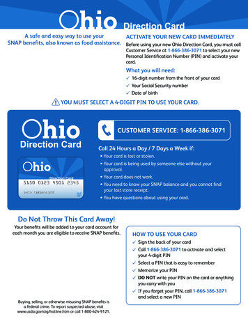
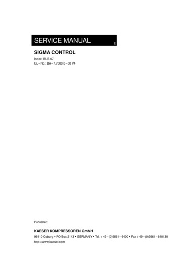
PerfectSpeed 16-Pin Variable Speed Motor Assembly8
Getting StartedThis troubleshooting guide provides field technicians a stepby step process for accurately diagnosing andtroubleshooting certain problems experienced by NidecPerfectSpeed 16-Pin motors. It does not override or replaceinstructions suggested by the manufacturer of the HVACsystem.To prevent misdiagnosis and unneeded repairs, operatorsshould try the steps listed in the Basic Troubleshootingsection first. If a problem still exists or there is an ongoingissue after following the steps in the Basic TroubleshootingSection, then go to the Control Unit Diagnostics section forfurther guidance.9
Basic TroubleshootingMotor isn’t spinning or runs abnormallyVerify thermostat is issuing call for activity.Check circuit breaker for trips or accidentalshutoff.Verify communication cable and power cord aresecurely connected to control unit connectors.Inspect for shorts, detached wiring, or looseconnections.Inspect control unit for broken or looseconnectors, moisture, excessive dirt, or otherdamage.Motor rattles or makes excessive noiseInspect motor and blower for accumulated dirt,internal debris or other signs of damage.Inspect blower fan for bent or missing blades,misaligned shaft, or unsecured mounting to shaft.Inspect blower housing for cracks, dents, orcorrosion.Inspect blower housing for secure mounting tosystem chassis.Inspect shaft; verify motor shaft spins freely byhand without effort and in both directions.10
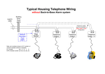
Motor & Control Unit DiagnosticsCheck 1: Diagnosis with UltraCheck-EZ Diagnostic Tool and 16X4W CableIf the UltraCheck-EZ diagnostic tool is not available, pleasecomplete Checks 3, 4, & 5 in order.NOTE: Only trained and qualified professionals familiar withPerfectSpeed 16-Pin motors should service the motor andcontrol.Connecting the UltraCheck-EZ Diagnostic Tool1. Disconnect or turn off AC power to the furnace, air handler,or equipment being serviced.2. Disconnect the 16-Pin communication connector from the16-Pin interface box [Figure 1].UltraCheck-EZ Diagnostic Tool16-Pin to 4-Wire Cable11
16-Pin Communication4-Wire CommunicationPowerFigure 13. Connect the 16-Pin cable connector of the UltraCheck-EZ diagnostic tool [Fig. 2] to the 16-Pin communicationconnector on the 16-Pin interface box [Fig. 1].Figure 24. Attach one of the alligator clips of the UltraCheck-EZ diagnostic tool [Figure 3] to a proper ground source.Figure 35. Attach the other alligator clip [Figure 3] to a proper 24 VACsource.12
There is no polarity between the alligator clips.The UltraCheck-EZ diagnostic tool is equipped with a nonreplaceable fuse. DO NOT connect the UltraCheck-EZ diagnostic tool to a power supply over 24 VAC. This willmake the UltraCheck-EZ diagnostic tool inoperable.Green LEDOrange PowerButtonFigure 46. Restore power to the furnace, air handler or equipment beingservicedWhen pressed, the orange button on the UltraCheck-EZ diagnostic tool sends a signal to the PerfectSpeed 16-Pinmotor to rotate. There may be a 5 second delay between thetime the button is pushed and the motor begins to rotate. Ifthe orange button doesn’t illuminate when pressed, thediagnostic tool is not properly connected to a 24 VAC supplyor may be inoperable.The green LED indicates when the PerfectSpeed 16-Pinmotor is communicating with the UltraCheck-EZ diagnostictool. If the green LED doesn’t blink, the control unit shouldbe replaced.13
7. Use the table below to determine needed action. Completesteps 8-11 before proceeding to the next check. Press theorange button [Figure 4] on the UltraCheck-EZ diagnostictool and wait 5 seconds for the blower to ot LitNot LitNotRotatingIf button does not illuminate when power button isdepressed, verify 24 VAC is available at alligatorclips. If 24 VAC is verified, the UltraCheck-EZ diagnostic tool is inoperable.LitBlinkingRotatingMotor and control unit are functioning properly.LitNot LitRotatingControl unit should be replaced if 16-Pin Box isattached. DO NOT remove 16-Pin Box from motor ifattached. Replace 16-Pin Box only, if box is detached.LitBlinkingNotRotatingFurther investigation required. Proceed to Check4 (page 19) to verify motor operation.Not LitNotRotatingControl unit should be replaced if 16-Pin Box isattached. DO NOT remove 16-Pin Box from motor ifattached. Replace 16-Pin Box only, if box is detached.Proceed to check 4 to verify motor is still operational.Lit8. Press the orange button [Figure 4] again to stop the blowerand turn off the UltraCheck-EZ diagnostic tool.If timeout feature in 16-Pin Box is not enabled themotor will not turn off by pressing the orange button. You mustdisconnect or turn off AC power to the furnace, air handler, orequipment being serviced.9. Disconnect or turn off AC power to the furnace, air handler,or equipment being serviced.10. Remove both alligator clips [Figure 3] from the 24 VACand ground connections.11. Reconnect the four wire communication connector to thecontrol unit connector [Figure 1].12. Restore power to the furnace, air handler or system beingserviced.14
Check 2: Diagnosis with UltraCheck-EZ Diagnostic ToolIf the UltraCheck-EZ diagnostic tool is not available, pleasecomplete Checks 3, 4, & 5 in order.Only trained and qualified professionals familiar with PerfectSpeed 16-Pinmotors should service the motor and control unit.Connecting the UltraCheck-EZ Diagnostic Tool1. Disconnect or turn off AC power to the furnace, air handler,or equipment being serviced.2. Disconnect the 4-wire communication cable from the controlunit connector [Figure 5].Figure 515
3. Connect the 4-wire connector of the UltraCheck-EZ diagnostic tool[Fig. 6] to the control unit communication connector [Fig. 5].Figure 64. Attach one of the alligator clips of the UltraCheck-EZ diagnostictool [Figure 7] to a proper ground sourceFigure 75. Attach the other alligator clip [Figure 7] to a proper 24 VAC source.There is no polarity between the alligator clips.The UltraCheck-EZ diagnostic tool is equipped with a nonreplaceable fuse. DO NOT connect the UltraCheck-EZ diagnostictool to a power supply over 24 VAC. This will make the UltraCheckEZ diagnostic tool inoperable.Green LEDOrange PowerButtonFigure 86. Restore power to the furnace, air handler or equipment being serviced.16
When pressed, the orange button on the UltraCheck-EZ diagnostictool sends a signal to the PerfectSpeed 16-Pin motor to rotate.There may be a 5 second delay between the time the button ispushed and the motor begins to rotate. If the orange button doesn’tilluminate when pressed, the diagnostic tool is not properlyconnected to a 24 VAC supply or may be inoperable.The green LED indicates when the PerfectSpeed 16-Pin motor iscommunicating with the UltraCheck-EZ diagnostic tool. If thegreen LED doesn’t blink, the control unit should be replaced.7. Use the table below to determine needed action. Complete steps 811 before proceeding to the next check. Press the orange button[Figure 8] on the UltraCheck-EZ diagnostic tool and wait 5seconds for the blower to spin.OrangePowerButtonGreen16LEDMotorBlowerNot LitNot LitNotRotatingIf button does not illuminate when power button isdepressed, verify 24 VAC is available at alligatorclips. If 24 VAC is verified, the UltraCheck-EZ diagnostic tool is inoperable.LitBlinkingRotatingMotor and control unit are functioning properly.LitNot LitRotatingControl unit should be replaced.LitBlinkingFurther investigation required. Proceed to Check4 (page 19) to verify motor operation.LitNot LitNotRotatingNotRotatingCommentsControl unit should be replaced. Proceed toCheck 4 to verify motor is still operational.17
8. Press the orange button [Figure 8] again to stop the blower and turnoff the UltraCheck-EZ diagnostic tool.9. Disconnect or turn off AC power to the furnace, air handler, orequipment being serviced.10. Remove both alligator clips [Figure 7] from the 24 VAC andground connections.11. Reconnect the 4-wire communication connector to the control unitconnector [Figure 5].12. Restore power to the furnace, air handler or equipment beingserviced.18
Check 3: Electrical Troubleshooting1. Disconnect or turn off power to the furnace, air handler, or systembeing serviced and wait 2 minutes. This allows the capacitors in thecontrol unit to fully discharge.2. Check the rotation and speed of the blower fan. Determine if theblower fan can spin freely manually, without effort or assistedmeans. If binding occurs, the motor needs to be replaced.3. Determine if HVAC system is wired for 120 VAC power, 240 VACpower or 277 VAC. If system is wired for 120 VAC power, verify ajumper wire is installed between positions 1 and 2 of the power cordconnector. On systems wired for 240 VAC or 277 VAC, the jumperwire should be removed [Figure 9].Operating the motor at 240 V AC or 277 VAC with jumper wireinstalled will cause significant damage to the motor.Figure 919
4. Disconnect power cord from connector on the control unit. Inspectpower cord for bent, damaged or recessed wires and terminals. SeeFigure 5.Contact the HVAC manufacturer if power cord contains bent,damaged or recessed wires or terminals.5. Disconnect 4-wire communication cable from connector on controlunit. Inspect cable for bent, damaged or recessed wires andterminals. See Figure 5.Contact the HVAC manufacturer if communication cable containsbent, damaged or recessed wires or terminals.6. Restore or turn on power to the furnace, air handler or system beingserviced.7. Check the voltage between position 4 and 5 of the power cordconnector. See Figure 9.Contact HVAC manufacturer if system is rated for 120 VACpower, and the measured voltage between positions 4 and 5 isNOT 120 VAC.Contact HVAC manufacturer if system is rated for 240 VACpower, and the measured voltage between positions 4 and 5 isNOT 240 VAC.Contact HVAC manufacturer if system is rated for 277 VACpower, and the measured voltage between positions 4 and 5 isNOT 277 VAC.If the measured voltages are correct between positions 4 and 5for the 120 VAC or 240 VAC or 277 VAC system, go to step 8[page 20].20
8. Check the voltage between positions 1 and 4 of the communicationcable connector [Figure 10].If the measured voltage between positions 1 and 4 is NOT 30-35VDC,16 X 4 wire box attached to the Control; replace the Control. DONOT try to remove the 16 X 4 wire box from the Control.16 X 4 wire box remote mounted in the unit; replace the 16 X 4wire box.If the measured voltage between positions 1 and 4 is 30-35 VDC,go to step 9.If all electrical checks are okay, go to step 9 below.9. Disconnect or turn off AC power to the furnace, air handler, orsystem being serviced. Wait 2 minutes to allow the capacitors tofully discharge.10. Proceed to Check 4.Figure 1021
Check 4: Control Unit VerificationRemoving the Control Unit1. Disconnect or turn off AC power to the furnace, air handler orsystem being serviced. Wait 2 minutes to allow the capacitors tofully discharge.2. Remove 3 screws securing the motor and control unit together.Grasp the Control Unit and pull away from motor until both units areseparated. [Figure 11].The control on the motor contains potentiallyhazardous voltage.ScrewScrewScrewFigure 1122
4. Disconnect the 3-wire motor to control harness from the control[Figure 12] and remove control unit [Figure 11]. Inspect for bent,damaged, or recessed wires and terminals inside of connector.Replace control unit if three pin connector contains bent,damaged or recessed terminals3 Wire Motor - to - Control Harness3 Pin ConnectorFigure 125. Inspect the NTC thermistor inside of control unit for any cracksor breakage [Figure 13].Replace control unit if NTC thermistor is cracked or broken.NTC ThermistorFigure 1323
6. Inspect capacitors inside of control unit for bulging or swelling.[Figure 14].Replace control unit if capacitors are bulging or swollen.Figure 147. Check phase to phase resistance between each of the threephase pins in the harness connector [Figure 15]. Resistancelevels between any two pins should be greater than 100K.If the multimeter indicates resistance levels greater than100K, the control unit is functioning properly. Next to verifymotor functionality, proceed to Check 5 [page 24].Replace control if multimeter indicates resistance levels lowerthan 100K.3 Pin Harness ConnectorFigure 1524
Check 5: Motor Verification1. Disconnect or turn off AC power to the furnace, air handler, orsystem being serviced. Wait 2 minutes to allow the capacitors tofully discharge.2. Make sure the motor shaft spins freely without effort manuallyin both directions [Figure 16].If motor shaft spins freely, go to step 3 [page 25].Replace motor if the shaft does not spin freely without effortmanually.Figure 1625
Removing the Control Unit (if still mounted to the motor)3. Remove three screws securing the motor and control unit together.4. Grasp the control unit and pull away from motor until both unitsare separated [Figure 17].ScrewScrewScrewFigure 175. Disconnect the 3-wire motor-to-control harness from thecontrol [Figure 18] and remove control unit [Figure 17].Inspect for bent, damaged, or recessed wires and terminalsinside of connector.Replace control unit if the 3-pin connector contains bent,damaged, or recessed terminals.3 Wire Motor - to - Control Harness3 Pin ConnectorFigure 1826
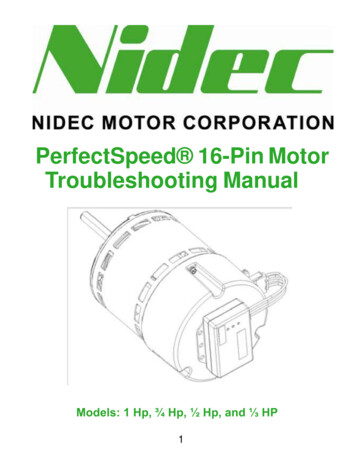
6. Inspect connector on back side of motor for bent, damaged, orrecessed wires and terminals [Figure 19].Replace motor if the connector contains bent, damaged, orrecessed wires or terminals.Figure 197. Check phase to phase resistance between each of the threephase terminals in the motor connector [Figure 19].NOTE: Resistance levels between any two contactsshould be equal.If resistance levels are equal, the motor is functioningproperly.Replace motor if the resistance levels are not equal.Replace motor if the resistance levels are open or shortcircuited.27
8. Inspect the magnets through the back side of motor forbroken or chipped magnets on the rotor core [Figure 20].Replace motor if magnets on the rotor core are broken or chipped.Magnet27Figure 20If both motor and control unit appear to be functioning correctly,reassemble motor and control unit and contact the HVAC systemmanufacturer.28
Final ChecksCheck mounting and fastening of motor and control. Make surecontrol unit and motor are securely attached together andmounted tightly in the HVAC system.Check control unit connectors. Inspect for shorts, detachedwiring, or loose connections.Check power cord and communication cable connections.Make sure both are securely connected to control unitconnectors.Check blower motor and verify wheel rotation. Make sure it spinsfreely manually without effort or assisted means in bothdirections.Check circuit breakers.8050 W. Florissant Avenue†All marks shown within this document are properties of their respective owners.Nidec Motor Corporation, 2012; All Rights Reserved. U.S. Motors , PerfectSpeed , and Ultracheck-EZ are registered trademarks of Nidec Motor Corporation.Nidec Motor Corporation trademarks followed by the symbol are registered with the U.S. Patent and Trademark Office.*RP915*RP91529F407911160000
About the PerfectSpeed 16-Pin Motor The PerfectSpeed , 16-Pin, ECM Variable Speed Motor easily integrates into non-communicating systems through a state of the art interface. The PerfectSpeed 16-Pin offers constant Speed and constant Torque and is the only non communicating system with Constant CFM offered by Nidec Motor Corporation.