Transcription
P/N 830-0058-0OSR 12-S-1495OPERATOR MANUALPVS-14AMonocular Night Vision DeviceNivisys, LLC400 S. Clark DriveSuite 105Tempe, AZ 85281 USA480-970-3222 (tel)480-970-3555 (fax)info@nivisys.comwww.nivisys.comExport of the commodities described herein is strictly prohibited without a validexport license issued by the U.S. Department of State Office of Defense TradeControls prescribed in the International Traffic in Arms Regulations (ITAR) Title 22,Code of Federal Regulation, Chapter 1, Subchapter M, Parts 120-130.
Inside cover intentionally left blank.
OPERATOR MANUALforPVS-14AMonocular Night Vision DeviceALL RIGHTS RESERVEDThis document contains proprietary information developed by Nivisys,LLC. It has been prepared to instruct Nivisys customers in the propercare and operation of the equipment respective to this document.Neither receipt nor possession thereof confers any right to reproduceor use, or disclose, in whole or in part, any such information withoutwritten authorization from Nivisys, LLC. 2011 Nivisys.Nivisys, LLC Rev. 25 Mar 2015i
This page intentionally left blank.Nivisys, LLC Rev. 25 Mar 2015ii
ADVISORY OVERVIEWThe following description categorizes the level of risk associated witheach cautionary statement displayed throughout the manual.WARNINGhighlights an operation orprocedure which, if not strictlyobserved, could result in injury to ordeath of personnel.CAUTIONhighlights an operation orprocedure which, if not strictlyobserved, could result in damage toor destruction of equipment or lossof mission effectiveness.NOTEhighlights an essential operation,procedure, condition or statement.Nivisys, LLC Rev. 25 Mar 2015iii
This page intentionally left blank.Nivisys, LLC Rev. 25 Mar 2015iv
Table of ContentsAdvisory Overview iiiTable of Contents vList of Figures viiList of Tables ixCHAPTER 1: GENERAL INFORMATION1-11.1Introduction 1-11.2Equipment Description 1-11.3Standard Kit Parts List1-21.4Standard Kit Parts Illustration1-31.5Optional Items List 1-41.6Optional Items Illustration1-51.7System Performance and Data1-6CHAPTER 2: PREPARATION FOR USE2-12.1Introduction 2-12.2Battery Precautions 2-12.3Battery Installation 2-32.4Eyecup Installation 2-32.5Demist Shield Installation2-42.6Sacrificial Window Installation 2-42.7Headmount Adjustment and Installation2-52.8Head/Helmet Mount Installation2-72.9Installation of Weapon Mount (Optional)2-9Nivisys, LLC Rev. 25 Mar 2015v
Table of Contents (cont.)CHAPTER 3: OPERATING INSTRUCTIONS3-13.1Introduction 3-13.2Controls and Indicators3-13.3Hand-held Operation 3-43.4Head Mounted Operation3-53.5Operations with IR Source3-83.6Using the Gain Control3-83.7Operation in Conditions of Blowing Dust or Sand3-93.8Operation in Rainy or Humid Conditions3-103.9Operation in Salt Water Areas3-103.10Shutting Down the Unit3-103.11Preparation for Storage3-10CHAPTER 4: MAINTENANCE INSTRUCTIONS4-14.1Introduction 4-14.2Deactivation 4-14.3Battery Removal4-14.4Cleaning the PVS-14A4-14.5Cleaning the Optics4-24.6Checking for Damage and Corrosion4-2CHAPTER 5: TROUBLESHOOTING 5-15.1Troubleshooting Procedures 5-1APPENDIX A: SPARE AND REPAIR PARTS LISTA-1A.1Introduction A-1A.2Contact Information A-1A.3Spare Parts List A-1APPENDIX B: WARRANTY INFORMATION B-1Nivisys, LLC Rev. 25 Mar 2015vi
List of FIGURES1-11-22-12-22-32-43-13-23-3Standard Kit Parts Illustration1-3Optional Parts Illustration1-5Standard Installations 2-3Headmount Diagram 2-7Head/Helmet Mount Adapter Installation2-8Weapon Mount Installation2-10Controls and Indicators3-2Head Mounted Operation3-7Gain Control 3-9Nivisys, LLC Rev. 25 Mar 2015vii
This page intentionally left blank.Nivisys, LLC Rev. 25 Mar 2015viii
List of Tables1-11-21-33-15-1A-1Standard Kit Parts List1-2Optional Items List1-4System Performance and Data1-6Controls and Indicators3-3Troubleshooting 5-1Spare and Repair Parts ListA-1Nivisys, LLC Rev. 25 Mar 2015ix
This page intentionally left blank.Nivisys, LLC Rev. 25 Mar 2015x
CHAPTER 1:GENERAL INFORMATION1.1Introduction:This manual provides operation and field level maintenanceinstructions for the PVS-14A. It also provides specifications anddata on the performance of the monocular. To ensure the safetyof the operator and the correct operation of the monocular it isrecommended that this manual is read carefully in its entiretybefore any deployment or field application.1.2Equipment Description:The PVS-14A is a self-contained night vision device thatenables improved night vision using ambient light from thenight sky. Typically the moon, star and/or sky glow.Optically, it is made up of an objective lens, image intensifierand eyepiece lens. The objective lens collects light reflectedfrom the night scene by the moon, stars, or night sky, invertsthe image and focuses that image on the image intensifier. Theimage intensifier converts the captured light into a visible imageand reinverts the image which can then be viewed through theeyepiece lens.In situations where there is no light at all the unit can beswitched into the infrared (IR) mode. The PVS-14A isequipped with an IR flashlight enabling the unit to use thisinvisible light to operate.The PVS-14A is designed for differences in the physicalfeatures of individuals. This allows for a wide range ofoperators to use the system safely and comfortably. Someof these design features are the power switch, eye reliefNivisys, LLC Rev. 25 Mar 20151-1
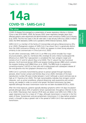
adjustment, diopter adjustment, gain control, and objectivefocus. Lightweight and versatile, the PVS-14A can be handheld, head-mounted, helmet-mounted, camera/camcorderadapted or weapon mounted as a tactical night scope. The PVS14A is the most widely fielded night vision system available.1.3Standard Kit Parts List:The standard PVS-14A kit comes with the items listed in thefollowing table.ItemPart No.DescriptionQty.1PVS-3000Monocular Assembly12580-0001-0AA Alkaline Battery23A3256353Demist Shield14A3144267Shoulder Strap15A3144264Sacrificial Lens16170-10Lens Tissue (packet)17830-0058-0Operator Manual18830-0059-0Quick Reference Guide (QRG)19A3187392Soft Carrying Case110A3256347Weapon Mount111A3256348Head/Helmet Mount Adapter112A3144268Headmount Assembly w/ Brow Pads1Table 1-1 Standard Kit Parts ListNivisys, LLC Rev. 25 Mar 20151-2
1.4Standard Kit Parts Illustration:The illustration below is provided for quick identification of thestandard parts of the PVS-14A kit.Figure 1-1 Standard Kit Parts IllustrationNivisys, LLC Rev. 25 Mar 20151-3
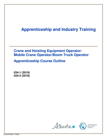
1.5Optional Items List:The PVS-14A is compatible with the following optional itemsand accessories listed in the following table.ItemPart No.Description17B257-2FShipping/Storage Case2A3260933Tethering Cord3A3256368PASGT Helmet Mount, Flip-Up4A3187430Magnetic Compass5AA-473000-045X Afocal Lens6A32563913X Afocal Lens7A3256345Shuttered EyeguardTable 1-2 Optional Items ListNivisys, LLC Rev. 25 Mar 20151-4
1.6Optional Items Illustration:The illustration is provided as a visual key to optional items thatcan be used with the standard PVS-14A.Figure 1-2 Optional Parts IllustrationNivisys, LLC Rev. 25 Mar 20151-5
1.7System Performance and Data:The chart below lists the technical specifications and data ofthe PVS-14A system. The data contained herein is subject tochange without notice.ITEMLIMITSElectrical DataPower SourceBattery (1.5V DC max.)Battery Requirements1 AA Alkaline or1 AA Lithium L91Battery Life (AA Alkaline)40 hrs @ 21 C (70 F)Battery Life (Lithium)40 hrs @ 21 C (70 F)Physical DataSoft Carrying Case Dimensions17.8cm x 30.1cm x 7.6cm(7” x 12” x 3”)Monocular Dimensions11.4cm x 5.0cm x 5.7cmMonocular Weight, with battery346gOptical DataMagnification1.0XField of View40 ( /-2 )Eyepiece of Focus 2 to -6 dioptersFocus Range25 cm (9.8”) to infinityEye Relief25 mmTable 1-3 System Performance and DataNivisys, LLC Rev. 25 Mar 20151-6
Objective Lensf/1.2Resolutionup to 1.3 cy/mR with 64 lp/mmtubeEnvironmental DataOperating Temperature-51 C to 50 CStorage Temperature-51 C to 85 CIllumination RequiredOvercast starlight to moonlightImmersion5 meter for 30 minutesTable 1-3 System Performance and Data, (cont.)Nivisys, LLC Rev. 25 Mar 20151-7
This page intentionally left blank.Nivisys, LLC Rev. 25 Mar 20151-8
CHAPTER 2:PREPARATION FOR USE2.1Introduction:This section contains instructions for installing and attachingvarious components and accessories to the PVS-14A foroperation under normal conditions.2.2 Battery Precautions:WARNINGDo not mix alkaline and lithiumbatteries. Do not mix old and newbatteries. Do not mix brands ofbatteries. do not mix disposable andrechargeable batteries. Failure tofollow these instructions could resultin death, injury or imposition of longterm health hazards.WarningInspect batteries for bulging priorto use. If the battery shows signs ofbulging, do not use.WarningDO NOT HEAT, PUNCTURE, DISASSEMBLE,SHORT CIRCUIT, Incinerate, ATTEMPT TORECHARGE OR OTHERWISE TAMPER WITHTHE BATTERIES. TURN OFF the PVS-14A IFthe BATTERY COMPARTMENT BECOMESUNDULY HOT.Nivisys, LLC Rev. 25 Mar 20152-1
IF POSSIBLE, WAIT UNTIL THE BATTERIESHAVE COOLED BEFORE REMOVING THEM.WarningDo not replace batteries in apotentially explosive atmosphere.Contact sparking may occur whileinstalling or removing batteriesandcausean explosion. Failure to followthese instructions could result indeath, injury or imposition of longterm health hazards.CAUTIONObey the battery manufacturer’sdirections for battery disposal.Nivisys, LLC Rev. 25 Mar 20152-2
2.3 Battery Installation:Install one (1) AA battery as follows.1.2.3.4.5.Remove the battery cap by turning it counter-clockwise.Check to ensure the o-ring is present. If not, replace it.Observe polarity as indicated on the outside of the batterycompartment.Insert battery into the battery compartment, plus ( ) endfirst.Replace battery cap by pushing and turning it clockwise.Tighten it firmly to ensure a watertight seal.Figure 2-1 Standard Installations2.4Eyecup Installation:Perform the following procedure to install eyecup onto themonocular.1.Carefully press the eyecup over the end of the eyepiece lens.Nivisys, LLC Rev. 25 Mar 20152-3
2.2.5Rotate the eyecup into proper viewing position. Adjust forbest fit. The eyecup must seal around your eye and preventthe green glow from escaping.Demist Shield Installation:Perform the following procedures to install the demist shield onthe eyepiece lens.1. Carefully remove the eyecup.2. Carefully press the demist shield onto the eyepiece. Becareful not to smudge the eyepiece lens or demist shield.3. Replace the eyecup.CAUTIONIf the demist shield is wiped whilewet or with wet lens tissue, you willdamage the coating.NOTEIf inclement operating conditionsare expected to exist (e.g. significanttemperature change and highhumidity), install demist shield tominimize eyepiece lens fog prior toexecution of mission.2.6Sacrificial Window Installation:Perform the following procedure to install the sacrificialwindow onto the objective lens assembly.CAUTIONIf adverse operating conditions(BLOWING dust or sand) are expectedto exist, attach the sacrificialNivisys, LLC Rev. 25 Mar 20152-4
window to protect the objective lensfrom scratches or other damage.1.2.2.7If the objective lens cap is in place, remove it.Carefully push the sacrificial window onto the objectivelens until it stops. Turn the sacrificial window clockwiseuntil it snaps into place.Headmount Adjustment and Installation (Optional):Perform the following procedure to adjust and install theheadmount assembly.CAUTIONDo not put on the headmount whilethe monocular is attached.1.2.Prior to donning the headmount, loosen the four ends of thechinstrap approximately two inches from the sliding barbuckles.Firmly press the front and rear snaps in place.NOTEIf the headmount is too loose,remove the attached thin browpadand replace with either the mediumor thick browpad supplied with theheadmount.3.With both hands, grasp the neck pad and pull the harnessover your head and the neck pad down to the back of yourneck.Nivisys, LLC Rev. 25 Mar 20152-5
4.5.6.7.Holding the chin cup in position on chin, adjust both sidesof the chinstrap until you feel light pressure against yourchin. (DO NOT TIGHTEN.)Maintain the position of the chin cup and remove any slackfrom the chinstrap. (DO NOT TIGHTEN.)Ensure that the cross-strap is not twisted and remove slackby adjusting the vertical adjustment at the neck pad.Adjust chinstrap and vertical adjustment until the chin cupand headband are in a comfortable but firm position.NOTEAfter installing the monocular,minor strap adjustments may benecessary to achieve comfort.8.Install the head/helmet mount adapter.Nivisys, LLC Rev. 25 Mar 20152-6
Figure 2-2 Headmount Diagram2.8Head/ Helmet Mount Installation:Install the head/helmet mount adapter into the monocular byNivisys, LLC Rev. 25 Mar 20152-7
following the procedure.1. Align the thumbscrew with the threaded hole and tighten asshown in Figure 2-3.2. Locate the alignment boss on the headmount/helmet mountadapter that fits into a groove on the monocular.3. Make sure the boss on the adapter fits into the groove onthe monocular.4. Loosen the clamp knob and pivot the arm to the other sidefor PVS-14A use with the right eye.Figure 2-3 Head/Helmet Mount Adapter InstallationNivisys, LLC Rev. 25 Mar 20152-8
2-9Installation of Weapon Mount:Perform the following procedure to install the weapon mount.CAUTIONThe PVS-14A is not a weaponsight, however, it can be used inconjunction with a collimated dotsight or laser aiming device.NOTEIt is recommended that the eyecupbe replaced with the shutteredeyeguard during weapon mounteduse.1.2.3.Orient the monocular and weapon mount as shown inFigure 2-4. Be sure to align the alignment boss on theweapon mount with the alignment groove in the monocular.Screw in the thumbscrew to secure the monocular to theweapon mount.Loosen the clamping knob on the weapon mount. Positionthe weapon mount with the monocular onto the weapon’smounting rail. Tighten by turning the clamping knob.notea ratchet in the weapon mountprevents over tightening of theclamp. Turn until the knob clicks.4.Check the position of the monocular by holding the weaponin the normal firing position. Adjust the fore/aft positionof the monocular as necessary by loosening the clampingknob and repositioning the weapon mount on the weapon’smounting rail.Nivisys, LLC Rev. 25 Mar 20152-9
Figure 2-4 Weapon Mount InstallationNivisys, LLC Rev. 25 Mar 20152-10
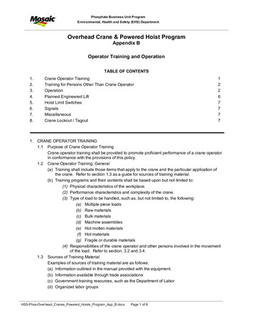
CHAPTER 3:OPERATIng instructions3.1Introduction:This chapter contains instructions for the safe operation of thePVS-14A under normal circumstances and environments.3.2 Controls and Indicators:The PVS-14A is designed to adjust for different users andcorrects for most differences in eyesight. The controls andindicators for the PVS-14A are shown in Figure 3-1 and aredescribed in Table 3-1.CAUTIONThe PVS-14A requires some ambient(moonlight, starlight, or artificiallight, etc.) to operate. The level ofperformance depends on the level oflight.Night light is reduced by passingcloud cover, while operating undertrees, in building shadows, etc.The PVS-14A is less effective viewinginto shadows and other darkenedareas.The PVS-14A is less effective throughrain, fog, sleet, snow, smoke, andother reflective material.Nivisys, LLC Rev. 25 Mar 20153-1
Figure 3-1 Controls and IndicatorsNivisys, LLC Rev. 25 Mar 20153-2
Control andIndicatorsFunctionsPower SwitchControls monocular and IR source, ON or OFF.RESET/OFFSame as system OFF.OFF also resets monocular after high light cutoff.ON activates the monocular.IR/PULL momentarily activates the IR sourcewhen the knob is turned clockwise. Pull andturn the knob clockwise from the ON position tocontinuously activate the IR source.CAUTIONDo not use excessive force toplace the power switch intothe momentary IR position.Low BatteryIndicatorA blinking yellow light indicates a low batterywith less than 30 minutes of battery liferemaining. It is visible through the eyepiece justoutside the intensified field-of-view.IR Source OnIndicatorA steady red light indicates that the IR source isON. It is visible through the eyepiece just outsidethe intensified field-of-view.Gain ControlAdjusts the system gain from a minimum valueof approximately 25 to a maximum value greaterthan 3,000.Table 3-1 Controls and IndicatorsNivisys, LLC Rev. 25 Mar 20153-3
Objective FocusFocuses objective lens. Adjusts for sharpestimage of viewed object.DiopterAdjustmentFocuses eyepiece lens to users eye. Adjust forsharpest image of intensifier screen.Eye ReliefAdjustmentAdjusts the distance between your eye and themonocular.LatchLatch used for separation of monocular fromheadmount/helmet mount adapter.Battery PolarityIndicatorThis feature, molded into the battery cartridge,shows the proper orientation of the batteries.High LightCut-offThe monocular will automatically cut offafter 70 30 seconds of operation in daylightor bright room light. Individual bright lights(headlights, flashlights, or other concentratedlight sources) will not actuate the high lightdetector located on the front of the monocular.To turn the monocular back ON, turn the powerswitch to RESET/OFF position and then to ONagain.Table 3-1 Controls and Indicators, (cont.)3.3Hand-held Operation:CAUTIONOperate the monocular onlyunder darkened conditions or usethe objective lens cap to coverthe objective lens for daylightconditions.Nivisys, LLC Rev. 25 Mar 20153-4
NOTEWhen using the monocular without amounting device, make sure to placethe neck cord around your neck.1.2.Ensure that the battery is installed correctly.Turn the power switch to ON.NOTEThe sharpest image will be observedonly when the objective lens andeyepiece lens are properly focused.3.4.3.4Rotate the diopter adjustment for the clearest view of theimage intensifier screen.Focus the objective lens while observing an object until thesharpest image is obtained.Head Mounted Operation:CAUTIONOperate the monocular only underdarkened conditions or use the lenscap to cover the objective lens fordaylight conditions.1.2.Ensure that battery is installed correctly.Put on the headmount following the instructions found inparagraph 2.7.Nivisys, LLC Rev. 25 Mar 20153-5
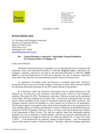
NOTETo make it easier to align themonocular, eyecup, and eyepiece lensto the eye, depress the eye reliefadjustment and slide the headmountsocket all the way forward beforeattaching the monocular.3.4.5.6.Align the headmount/helmet mount adapter’s latch to theheadmount socket. Press and hold down the latch leverwhile installing the monocular into the headmount socket.Release the latch when the monocular fully engages thesocket.Set your eye relief by depressing the eye relief adjustmentand move the monocular back toward your non-dominateeye until the eyecup comfortably seals around the eye.Turn the monocular ON.Loosen the clamp knob and adjust monocular until it isproperly aligned with your eye. Tighten the clamp knob tosecure the monocular.NOTEThe sharpest image will be observedonly when the objective lens andeyepiece lens are properly focused.7.Rotate the diopter adjustment for the clearest view of theimage intensifier screen.NOTEAny readjustment of eye reliefrequires readjustmentof the diopter.Nivisys, LLC Rev. 25 Mar 20153-6
8.Adjust the eye relief distance by pressing the eye reliefadjustment and sliding the monocular fore or aft to obtain afull field-of-view of the image. Reset the diopter adjustmentfor best image.9. Adjust the objective lens focus (Figure 3-1) while observingan object until the sharpest image is obtained.10. If the monocular is removed from the headmount whileoperating, the monocular will be powered OFF. To returnto normal operation, cycle the power switch knob from ONto OFF/RESET and back to ON.Figure 3-2 Head Mounted OperationNivisys, LLC Rev. 25 Mar 20153-7
3.5Operations with IR Source:WARNINGThe IR source is a light that isinvisible to the unaided eye foruse during conditions of extremedarkness. However, the light fromthe IR source can be detected by theenemy using night vision devices.NOTEThe purpose of the IR source is forviewing at close distances up to 3meters whenadditionalilluminationis needed.1.2.3.6Pull the power switch knob out and rotate clockwise to theIR position. With the monocular held to the eye, observethat a red light appears in the eyepiece. This indicates thatthe IR source is operating.For momentary IR use, turn the power switch knobclockwise (without pulling) past the ON position. Observethat a red light appears in the eyepiece. When the switchknob is released, the knob will return to the ON positionand the IR source will be powered OFF.Using the Gain Control:Turn the gain control to provide the optimum illumination inputto the eye.Nivisys, LLC Rev. 25 Mar 20153-8
Figure 3-3 Gain Control3.7Operation in Conditions of Blowing Dust or Sand:CAUTIONOperation in conditions of blowingdust or sand can pit and scratchthe optical elements and damagethe mechanical components unlessthe precautions given below areobserved.1.2.3.Ensure that the sacrificial window is in place.Avoid pointing the monocular into the wind unlessnecessary for operation.Keep the carrying case closed unless removing or replacingitems.Nivisys, LLC Rev. 25 Mar 20153-9
4.3.8Ensure that all dust and sand is removed from the PVS-14Aand carrying case after operation.Operation in Rainy or Humid Conditions:CAUTIONOperation in rainy or humidconditions can cause corrosion anddeterioration of the PVS-14A unlessthe precautions given below areobserved1.2.3.4.Install the demist shield as instructed in this manual.Keep the carrying case closed unless removing or replacingitems.Dry the monocular, mounts, and accessories after exposureto rain or high humidity and before storage.Do not store monocular in a wet carrying case.3.9Operation in Salt Water Areas:After exposure to salt water, clean the unit as instructed in thismanual, after rinsing with fresh water.3.10Shutting Down the Unit:Perform the following procedures to shut down the monocular.1. Turn the monocular power switch to the OFF position.2. Remove the monocular from the headmount, helmetmount or weapon and remove the weapon mount from themonocular.3.11Preparation for Storage:1. Remove battery from the monocular.2. Inspect the battery housing for corrosion or moisture. CleanNivisys, LLC Rev. 25 Mar 20153-10
3.4.and dry if necessary.Replace the battery cap.Remove the demist shield or sacrificial window if installed.Install objective lens cap.NOTEPrior to placing PVS-14A into carryingcase, ensure PVS-14A and case are freeof dirt, dust, and moisture.5.6.Place the monocular, accessories and cleaning suppliesback into their storage/carrying case. It is best to placethe items in their original locations to prevent any possibledamage to the unit and/or accessories.Return to storage area.Nivisys, LLC Rev. 25 Mar 20153-11
This page intentionally left blank.Nivisys, LLC Rev. 25 Mar 20153-12
CHAPTER 4:Maintenance instructions4.1Introduction:The PVS-14A is designed to be used in diverse environmentsand rugged conditions. It is recommended that regularand simple maintenance be preformed for optimal systemperformance.CAUTIONThe monocular isaprecision electrooptical instrument and must behandled carefully.Do not scratch the external lenssurfaces or touch them with yourfingers.Wiping demist shield with lens TISSUEwhile wet or with wet lens TISSUE candamage the coating.4.2Deactivation:Power down the system by turning the power switch knob toOFF.4.3 Battery Removal:Open battery compartment, remove battery and store in carryingcase. Close the battery compartment before cleaning.4.4 Cleaning the PVS-14A:When necessary, use a moistened clean cloth to wipe the outsideof the unit, EXCEPT FOR THE OPTICAL SURFACES.Nivisys, LLC Rev. 25 Mar 20154-1
Be sure to wipe away excess dirt and dust that may restrictthe performance of and damage moving and mating parts.If needed, the use of a very diluted detergent solution ispermissible. Dry with a soft clean cloth, or allow unit to air-drybefore storing it.4.5 Cleaning the Optics:When cleaning of the lens is required, first blow any loosedirt or grit away from the surface of the lens. EXCEPT FORTHE DEMIST SHIELD, use the supplied lens tissue lightlymoistened with water or lens cleaning fluid to lightly wipe theoptical surfaces, using a circular motion. Discard each lenstissue after one use to avoid transferring grit or foreign matteronto the lens surfaces. If the lens remains dirty use a cottonswab lightly moistened with lens cleaning fluid to remove theforeign matter from the lens. Dry with a clean unused lenstissue.4.6 Checking for Damage and Corrosion:As a general guideline, conduct an inspection of thePVS-14A, accessories, and the case after every use. Lookfor heavy wear and cracks in rubber or plastic. Inspect formoisture or corrosion in electronic housings and in the batterycompartment. Check for scratches, condensation and foreignmatter on optical surfaces. Report missing or damaged items,for replacement.Nivisys, LLC Rev. 25 Mar 20154-2
CHAPTER 5:TROUBLESHOOTING5.1Troubleshooting Procedures:Table 5-1 lists common malfunctions that may occur with theequipment. Perform the tests, inspections and corrective actionsin the order they appear in the table.This table cannot list all the malfunctions that may occur, allthe tests and inspections needed to find the fault, or all thecorrective actions needed to correct the fault. If the equipmentmalfunction is not listed or actions listed do not correct the fault,notify your maintainer.MalfunctionTest for InspectionCorrective ActionMonocularfails toactivate.Visual.Turn switch to RESET/OFFposition and then ON.Check for defective,missing or improperlyinstalled battery.Replace battery or installcorrectly.If PVS-14A still fails toactivate, refer to higherlevel of maintenance.Table 5-1 TroubleshootingNivisys, LLC Rev. 25 Mar 20155-1
IR sourcefails toactivate.In a dark locationIf IR source still fails towith system turnedactivate, refer to higheron, activate IR source. level of maintenance.Visually check IRsource operation; sceneshould brighten.IR sourceindicatorfails toactivate.Visual.Refer to higher level ofmaintenance.Poor imagequality.Check objective lensor eyepiece.Refocus.Check for fogging ordirt on objective lensor eyepiece lens.Clean lens surface perparagraph 4.5.Check eye reliefdistance.Readjust for proper eyerelief distance.Light visiblearoundeyecup.Check eyecup forresiliency.If eyecup is defective,refer to higher level ofmaintenance.Diopteradjustmentcannot bemade.Check to see if thediopter adjustment isbent or broken.If damaged, refer to higherlevel of maintenance.Head strapscannot betightened.Check for defectivebuckles, fasteners orstraps.If damaged, refer to higherlevel of maintenance.Table 5-1 Troubleshooting, (cont.)Nivisys, LLC Rev. 25 Mar 20155-2
Headmountsocket andheadmountadapter latchdo not catch.Check socket or latchfor dirt.Clean socket and latch.Check socket or latchfor damage.If damaged, return eitherheadmount to higher levelof maintenance.Monoculardoes not cutoff whenexposed tohigh light.Visual.If damaged, return to higherlevel of maintenance.Perform the followingtest under daylight orbright room light (notfluorescent light).Place the objectivelens cap on theobjective lens. Turnmonocular ON andobserve that it cuts offwithin 70 30 secondsafter energized.Turn monocularOFF and then ON toreenergize monocular.Table 5-1 Troubleshooting, (cont.)Nivisys, LLC Rev. 25 Mar 20155-3
This page intentionally left blank.Nivisys, LLC Rev. 25 Mar 20155-4
APPENDIX A:SPARE AND REPAIR PARTS LISTA.1Introduction:This section provides information needed to identify, contactand order spare and/or repair parts for the PVS-14A.A.2 Contact Information:To order spare or repair parts for the PVS-14A or any of yournight vision products contact:Nivisys, LLC400 S. Clark Drive, Suite #105Tempe, Arizona 85281 USAPhone: 1-480-970-3222Fax: 1-480-970-3555A.3Spare Parts List:The following is a list of parts that may be ordered for spareparts for the PVS-14A.Part No.DescriptionQty.A3144404Switch Knob Assembly1A3144315Purge Screw1A3144316Purge Screw O-Ring1A3144306Neck Cord1A3144318Objective Lens Cap1Table A-1 Spare and Repair Parts ListNivisys, LLC Rev. 25 Mar 2015A-1
A3144422Eyecup Assembly1A3256345Shuttered Eyeguard1A3256353Demist Shield1A3144268Headmount Assembly with Brow Pads1A3144264Sacrificial Window1A3256368PASGT Helmet Mount, Flip-Up1A3187430Magnetic Compass17B257-2FShipping/Storage Case1A3187392Soft Carrying Case1830-0058-0Operator Manual1830-0059-0Quick Reference Guide1A3144267Shoulder Strap1A3256351Variable Gain Knob1A3256348Weapon Mount1A3256347Head/Helmet Mount Adapter1A3144292Elevation Strap1A3144290Neckpad1A3144293Side Strap1A3144436Browpad, Thick1A3144435Browpad, Medium1Browpad, Thin1A3144280Table A-1 Spare and Repair Parts List, (cont.)Nivisys, LLC Rev. 25 Mar 2015A-2
APPENDIX B:WARRANTY INFORMATIONEquipment Warranties And Remedy:Seller warrants that each newly manufactured item sold hereunderand such portion of a repaired/refurbished item as has been repairedor replaced by Seller under this warranty, shall be free from defectsin material or workmanship at the time of shipment and shall performduring the warranty period in accordance with the specificationsincorporated herein. Should any failure to conform to these warrantiesbe discovered and brought to Seller’s attention during the warrantyperiod and be substantiated by examination at Seller’s factory or byauthorized field personnel, then at its own cost, Seller shall correctsuch failure by, at Seller’s option, repair or replacement of the nonconforming item or portion thereof, or return the unit purchase price ofthe non-conforming item or component. Buyer agrees that this remedyshall be its sole and exclusive remedy ag
APPENDIX b: WARRANTY INfORMATION b-1. Nivisys, LLC Rev. 25 Mar 2015 vii LIST Of fIGURES 1-1 Standard Kit Parts Illustration 1-3 1-2 Optional Parts Illustration 1-5 2-1 Standard Installations 2-3 2-2 Headmount Diagram 2-7 2-3 Head/Helmet Mount Adapter Installation 2-8 2-4 Weapon Mount Installation 2-10 .