Transcription
Verifying Interfaces and Generating Interface ControlDocuments for the Alignment and Phasing Subsystem of theThirty Meter Telescope from a System Model in SysMLSebastian J. I. Herziga , Robert Karbana , Gary Bracka , Scott B. Michaelsb , Frank Dekensa , andMitchell TroyaaJet Propulsion Laboratory, California Institute of Technology, Pasadena, CA, USAbThirty Meter Telescope, Pasadena, CA, USAABSTRACTThis paper presents a novel method for verifying interfaces and generating interface control documents (ICDs)from a system model in SysMLTM . In systems and software engineering, ICDs are key artifacts that specifythe interface(s) to a system or subsystem, and are used to control the documentation of these interfaces. ICDsenable independent teams to develop connecting systems that use the specified interfaces. In the context ofthe Thirty Meter Telescope (TMT), interface control documents also act as contracts for delivered subsystems.The Alignment and Phasing system (APS) is one such subsystem. APS is required to implement a particularinterface, and formulates requirements for the interfaces to be provided by other components of TMT thatinterface with APS. As the design of APS matures, these interfaces are frequently refined, making it necessaryfor related ICDs to be updated. In current systems engineering practice, ICDs are maintained manually. Thismanual maintenance can lead to a loss in integrity and accuracy of the documents over time, resulting in thedocuments no longer reflecting the actual state of the interfaces of a system. We show how a system model inSysMLTM can be used to generate ICDs automatically. The method is demonstrated through application tointerface control documents pertaining to APS. Specifically, we apply the method to the interface of APS to theprimary mirror control system (M1CS) and of APS to the Telescope Control System (TCS). We evaluate thenewly introduced method through application to two case studies.Keywords: Interface Control Documents, Model-based Systems Engineering, SysML, TMT, APS1. INTRODUCTIONThe Thirty Meter Telescope (TMT) is a proposed astronomical observatory with an extremely large telescope.Its subsystems are developed by numerous institutions and organizations from around the world. To coordinatethis largely independent development of the subsystems, interfaces between subsystems are actively managedand have been specified early in the design process. Interface Control Documents (ICD) can specify software,mechanical, optical, power, thermal, and other interfaces. Interfaces may evolve as the design is refined. Achallenge is to verify whether the system under design remains in compliance with the specified interfaces, anddetect any non-compliance as early as possible. Any discrepancy may require the interface control document, orthe system specification to be updated. This paper takes one step towards streamlining interface verification andICD generation, and introduces and evaluates a method for deriving the software interfaces of the Alignment andPhasing System (APS) to its interfacing subsystems through static analysis of the specified behavior of APS. Acomparison of these derived interfaces to the change controlled ICDs (which act as the authoritative source forinterface specifications) yields a basis for verification.In current systems engineering practice, verifying compliance to interfaces is largely a manual effort, involvinginspection, testing and reviews. TMT has developed an ICD database and management system,1 in whichinterfaces are stored in a machine readable form. Several tools are available for processing and validating theinterface specifications. However, the interface specifications still have to be produced by some external entity Further author information:S. J. I. Herzig: E-mail: sebastian.j.herzig@jpl.nasa.gov, Telephone: 1 818 393 3059
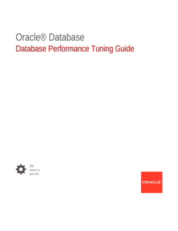
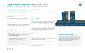
e.g., by a systems engineering team - and adherence of the designed (sub-)system to the interface specificationshas to be ensured manually.The APS systems engineering team is following the Model-based Systems Engineering paradigm, and isdeveloping a system model of TMT and APS in SysMLTM . This system model contains requirements, behavioralspecifications, structural specifications, and relationships between these aspects. While SysMLTM also offersconstructs for defining interfaces, these interface specifications cannot formally be connected to the behavior ofthe component realizing or using the interface. Therefore, their use is limited, requiring careful manual inspectionto ensure compliance to specified interfaces. Part of the structural and behavioral specification are the definitionof interactions between the various subsystems and their components. In the TMT / APS model, the softwareinteractions are modeled using a Signal processing mechanism, in which various types of Signals are sent andreceived by components, triggering changes in their state. In the approach introduced in this paper, we derivesoftware interfaces from these specified interactions. The working hypothesis is that sufficient information iscontained in, and can be extracted from the system model in order to recreate an ICD. Given the validity of thehypothesis, a mechanism could be put into place for automatically updating ICDs based on the latest behaviorspecifications. Verification activities could be facilitated through comparison of the derived ICD to a changecontrolled, agreed-upon ICD (i.e., an authoritative, externally managed ICD). Clearly, such a comparison canreveal discrepancies and non-conformance, and check completeness of the current interface specification.The remainder of this paper is structured as follows: in section 2 we briefly introduce the TMT system model,and review the state of practice in interface management with SysMLTM . This is followed by an introductionto our approach in section 3. Section 4 introduces methods for generating interface control documents from theextracted information. The approach is applied to two example interfacing subsystems in section 5. Results areanalyzed, and key insights discussed in detail. The paper closes with a summary of the most important findings,conclusions and suggestions for future work.2. BACKGROUND & RELATED WORKBefore introducing our approach, a brief introduction to the TMT / APS system model is provided in thissection. Also introduced are the constituents of an interface control document, and the state-of-the-art ofinterface management with UML / SysMLTM .2.1 The Thirty Meter Telescope System ModelThe Thirty Meter Telescope (TMT),2 under development by the TMT International Observatory (TIO), applies ahybrid systems engineering approach leveraging both traditional systems engineering and model-based techniquesto perform the systems engineering tasks such as requirements management, technical resource management, anddesign management and analysis. The main objective of MBSE for the TMT is to capture operational scenariosand demonstrate that requirements are satisfied by the design. For this purpose, a SysMLTM model is createdto better understand and communicate system behavior, motivated by optimizing the system design.The Jet Propulsion Laboratory (JPL) participates in the design and development of several subsystemsof TMT and delivers the complete APS. The TMT International Observatory (TIO) is the customer, whichprovides the APS team with requirements, and JPL delivers an operational realization of the system. TheAPS team pursues an MBSE approach to analyze the requirements, come up with an architecture design andeventually an implementation. Central to the implementation of MBSE on APS is the development of a systemmodel in SysMLTM . This system model integrates requirements, structure, behavior, and parametric relations.Its development is driven by operational scenarios, the integration of each of which refines the behavioral andstructural specification of APS.Both the structure and behavior of APS is captured in the system model. The structure includes the encapsulation of properties of a system, and the decomposition of a system by either functional or physical boundaries.Interfaces formally capture any and all exchange of information, energy or matter between components. Thecaptured behavior of each component specifies how the state and properties of a component change, and whenand how components interact. Requirements are imposed on both structure and behavior.3–5 In addition to APSand its components, TMT subsystems interfacing with APS are also modeled (see Figure 1). The behavioral
Figure 1. APS and TMT subsystems interfacing with APS (software interfaces).specification of these interfacing components is limited to reactions that are observable by an external entityupon receiving appropriate stimuli. The behavior of these interfacing subsystems is based on heritage designs,and is regularly reviewed by representatives from the responsible teams (during reviews of the implementation ofnewly integrated operational scenarios). Ports and connectors between ports signify the existence of interfacesbetween APS and the subsystems.By having adhered to the Executable Systems Engineering Method (ESEM),5 and through use of appropriatetools, the TMT / APS SysML model is executable (i.e., it is built for simulation and analysis purposes). ESEMprescribes the functional and physical decomposition of the system into a nested tree of components, as well asthe specification of the behavior of each. Requirements are formally captured through manual translation tomathematical constraints and the binding of any variables in these to behavioral or structural properties of thesystem. This allows for analytic links between requirements, use cases, system decomposition, system behaviorand subsystem relationships to be captured. A number of (first-order) analyses can be performed automatically,including the verification of requirements on power, mass, timing, and optical and pointing errors. To facilitaterequirements verification, we have modeled a number of operational scenarios of APS using SysMLTM . Thesystem model is available for download under an open source license .2.2 Elements of a Software Interface Control DocumentAn ICD is a document that describe the interface(s) to a system or subsystem. It may describe the inputs andoutputs of a single system or the interface between two systems or subsystems. An ICD should only describethe interface itself, and not the characteristics of the systems which realize or use it. In general, an ICD does Available at http://www.github.com/Open-MBEE/TMT-SysML-Model
not have to be a textual document, and can come in many forms. For instance, an application programminginterface (API) is a form of ICD. Interface descriptions can be created for software, optical, mechanical, thermal,and other interactions. Here, we focus on the content of software ICDs as used by TMT.TMT has developed an ICD management system, in which certain information pertaining to software interfaces between subsystems is stored in HOCON notation (a superset of JSON) using a TMT-specific schema.From these definitions, document-based ICDs can be directly generated. Typically, these documents describethe interface between two systems. However, the interface information in the TMT database defines the inputsand outputs to all interfacing subsystems, allowing for the generation of artifacts that describe the interface(s)of just one subsystem.In general, the software interface definitions in TMT ICDs describe commands that can be invoked or aresupported, and events that components publish or can subscribe to. Therefore, a TMT ICD that defines theinterface between two components A and B contains the following elements: Commands sent from A to B Commands sent from B to A Telemetry events published by B that A subscribes to Telemetry events published by A that B subscribes toFor each command, the following information is specified: Name of command Short description Detailed description Data format (the returned parameters / return type) Data units (the input parameters to the command)For each input parameter (or “data unit”), as well as for the returned parameters / return type (or “dataformat”) the following information is provided: Argument (parameter name) Data format (the type; e.g., float) Units (physical units; e.g., m (meters)) Range (valid range of values for input parameter) CommentsIn addition to the above, the return parameter specification also defines a maximum and a typical time thata command is expected to take to execute. Other, related documents, prescribe the communication protocolsand technical standards to be used in the implementation.TMT ICDs also describe the telemetry events published by a component, and those that a componentsubscribes to. The specification of these events includes: Name Frequency
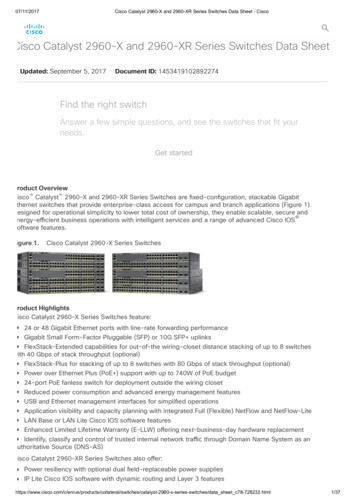
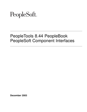
Figure 2. Hypothetical interface specification in SysMLTM and Blocks that use and realize the interface. Comment / description AttributesSimilar to parameters of commands, the specification of attributes of events include a specification of theirtypes, units, value ranges, and feature a short description.2.3 State of the Art of Interface Management with UML / SysMLSysMLTM , and more generally the Unified Modeling Language (UML) which SysMLTM is based on, definelanguage constructs for defining interfaces. An example of such an interface definition is illustrated in Figure 2.For software interfaces, it is typical to define operations and signal receptions. In UML and SysMLTM , interfacesare virtual constructs that are realized or used by one or more components. Different symbols are used todistinguish between these relationships. For instance, in Figure 2, Camera realizes the Camera Interface, whileControl Software simply uses the interface. This can be shown both by the different kinds of arrows pointing tothe interface, and by the “ball and socket” notation.Unfortunately, the UML and SysMLTM specifications are ambiguous about how a realizing classifier is expected to realize the features of its interfaces. The UML 2.4.1 specification stated that “‘for behavioral features,the implementing classifier will have an operation or reception for every operation or reception, respectively,defined by the interface.”’ (7.3.25, semantics).7 The current version, 2.5.1, has weakened this statement slightly,stating that “‘BehavioredClassifiers shall provide a public faade consisting of attributes, Operations, and externally observable Behavior that conforms to the Interface.”’ (10.4.3 Semantics).8 What this conformanceconsitutes is not unambiguously defined. The specification merely states that “‘if an Interface declares anattribute, this does not necessarily mean that the realizing BehavioredClassifier will necessarily have such anattribute in its implementation, but only that it will appear so to external observers.”’. Also stated is that “‘forBehavioralFeatures, the implementing BehavioredClassifier will have an Operation or Reception for every Operation or Reception, respectively, defined by the Interface”’, a statement that can also be found in the SysMLTMFigure 3. Example of a tool-specific (here: NoMagic MagicDraw) ICD table.6
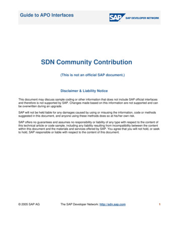
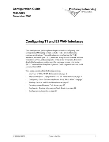
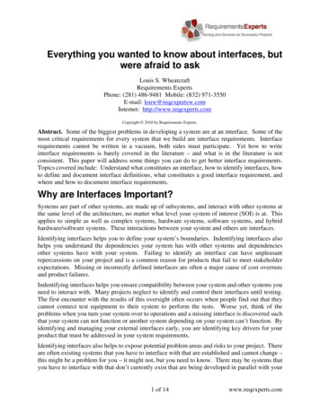
literature.9 This implies having to create an operation and signal reception for every operation and signal reception defined by the interface. However, the formal relation between the realized feature and the declared featureis not further defined. Furthermore, no statement is provided about the relationship between an interface andthe behavior of a BehavioredClassifier that is using the interface (such as the Control Software in Figure 2. Thismakes it unclear how, e.g., the operations specified by an interface can be invoked in behavioral specifications ofthe classifier relying on the interface.These ambiguities have resulted in a lack of support for verifying the specified behavior of a component againstits specified interface. Current tool-specific extensions for interface management are limited to and based on thedeclared interfaces, rather than the specified behavior. For instance, NoMagic MagicDraw defines “black box”and “white box” interface tables (see Figure 3), which can be created for any two components that are connectedthrough ports.6 The “white box” tables contain the features of the connecting interfaces. While this allows forproducing a summary view of the essential content typically found in an ICD, it still requires manual verificationand “double bookkeeping”, since the implementation of the interfaces must be carefully analyzed manually toensure conformance to the specified interface. Therefore, no guarantee can be made about the conformance to,and the completeness and correctness of the interface with respect to the specified behavior.3. EXTRACTING SOFTWARE INTERFACES THROUGH STATIC BEHAVIORANALYSISHere, we introduce an approach to deriving software interfaces from the specified behavior of a component usingstatic analysis of the interactions described in the behavioral specifications. The derived information can be usedas a basis for comparison and verification, and for the purpose of generating artifacts such as Interface ControlDocuments.Figure 4. Conceptual model: interfaces, and components of APS with their respective APS-internal interfaces.
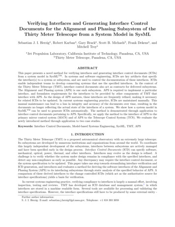
stm [State Machine] Procedure Executive and Analysis Software Behavior [ Use Case: Maintenance Alignment ]Maintenance AlignmentInitializingdo / InitializePEAS/ initTimerCorrecting Rigid Body and Segment FigureInitComplete /do / Rigid Body and Segment Figure correctionStandByMaintenance AlignmentFinished / diffTimeBroad Band Phasing 1umdo / Broad Band Phasing 1umAbortFinished / diffTimeNarrow Band PhasingFinished / FinalDiffTimedo / Narrow Band PhasingFinishedFigure 5. Excerpt of the specification of the Procedure Executive Analysis Software (PEAS) behavior as a state machine.3.1 Modeling Subsystem Interactions using SignalsAs stated in section 2, the specification of the operational behavior of APS and its components is driven byoperational scenarios.3 Many of these operational scenarios define interactions among subsystems of TMT andtheir components. For instance, mirror alignments performed by APS may require the primary, secondary, ortertiary mirror to be moved. The movement of the mirrors is controlled by other subsystems of TMT outsidethe authoritative domain of APS. Interfaces are negotiated between components to allow for commands to beinvoked, or telemetry data to be received from other subsystems. Throughout the TMT / APS system model,such interactions among components and subsystems are modeled using a message passing mechanism (usingSysMLTM Signals). It is these interactions that we use as a basis for deriving interface specifications.To illustrate this message-passing-based interaction mechanism, consider interactions between internal components of APS (see Figure 4). In most cases, the Procedure Executive Analysis Software (PEAS) plays a centralFigure 6. Interaction with Shack-Hartmann Camera: Take SH Exposure activity.
Figure 7. Specified behavior of SH filter (partial): (a) lifecycle behavior and (b) taking exposure.role. Figure 5 illustrates the specified behavior of PEAS during the operational scenario Maintenance Alignment.After initialization, PEAS is in a StandBy state. An external signal (provided, perhaps, by an operator) namedMaintenance Alignment triggers PEAS to transition to the Maintenance Alignment state. PEAS is specifiedto only be able to leave this state if an Abort signal is provided (internally or externally). Otherwise it proceedswith first correcting the rigid body and segment figure, then performs broad band phasing and finally narrowband phasing. The “do” behavior of each state specifies the behavior of PEAS when in that particular state.Once completed, PEAS returns to its StandBy state.Figure 6 illustrates part of the “do” behavior of PEAS. In the behavior, a signal SH Take exposure Cmd isspecified to be sent over the port PEAS2SHOut of PEAS (see Figure 4). Payload data is sent along with thesignal (here: dit, which is the exposure time). An excerpt of the state machine defining the lifecycle behaviorof the Shack-Hartmann (SH) Camera is shown in Figure 7 (left). If the SH camera is currently not in a statein which it is taking an exposure, receiving the signal SH Take exposure Cmd leads to a transition into the TakeExposure state. This, in turn, triggers the “do” behavior SendAck Take Exposure (see Figure 7 (right)), inwhich an exposure is taken, the detector is read out, and the results are sent back. PEAS is waiting for anacknowledgement by the SH Camera to have executed the command SH Take exposure Ack successfully. Asshown in Figure 7 (right), this acknowledgement is sent over the port CC SH2PEASOut which connects the SHcamera to PEAS.3.2 Deriving Software Interface through Static Analysis of System BehaviorIn the TMT / APS system model, we formally declare the existence of interactions among components orsubsystems (modeled using Blocks) using Ports and Connectors. In SysMLTM , Signals can be broadcast or sentover specific ports, and can have payload data attached to them. Actions with the semantics of sending (e.g.,Send Signal Actions) and waiting for the receipt of signals (e.g., Triggers) are native to SysMLTM , allowing formodeling of the invocation of remote behavior, and the communication between components through the sendingand receiving of messages.The sending of a Signal in one component, and its reception in another, can, therefore, be interpreted asthe invocation of a command or sending of telemetry data as part of the specified behavior. From this, one canderive that this interaction is intended to be part of the interface description. Repeating this process by parsingall specified behavior in the system model yields the desired interface information. Subsystems / assemblies /components interacting with one another are simply Blocks in the SysMLTM model. Interfaces are declared usingPorts and Connectors. Commands and Events correspond to Signals, and any of their attributes and parametersto Properties owned by the Signals. Types are simply SysMLTM Value Types. The protocol is apparent from thespecified behavior. Table 1 summarizes these correspondences between ICD concepts and SysMLTM constructs.While seemingly simple, there are a number of challenges associated with implementing this procedure.Firstly, Signals may be exchanged between components of a Subsystem A and another Subsystem B. This
Table 1. Mappings between elements specified in an ICD and their implementing SysML constructs.ICD ConceptSysML ConstructSubsystem / Assembly / ComponentBlockInterface DeclarationPort, ConnectorProtocolState Machine, ActivityCommandSignalSubscribe EventSignalPublish EventSignalParameter / AttributeProperty (of Signal)Returned DataProperty (of Signal)Data TypeValue Type, Blockrequires tracing the signal from the Port that it was sent over to all possible recipients: for instance, PEAS is acomponent of APS, which can send a Signal over one of its ports to M1CS or TCS (which are other subsystemsof TMT). This requires the signal to be traced from PEAS, to a port of APS, and to the receiving subsystem. Insome cases, Signals may be sent to more than one component if a port connects multiple other ports. Secondly,ports may be inherited by super-classes: such is the case with APS, which defines a ”Black Box” system, andsub-classes “Conceptual” and “Realization”, each of which inherit the interfaces defined by the “Black Box”system. A third challenge may be model organization: in the TMT / APS model, not all behavior intended tobe part of that of a component is necessarily owned by the component. This may require tracing the executioncontext through Call Behavior Actions defined in the context of owned behavior of the component. Algorithm 1summarizes the procedure for deriving software interface information from behavioral specifications in the systemmodel.input : System model SInvoking source component CsTarget component Ctoutput: A list sentCommands containing commands invoked by Cs in CtportsOnSource Ports on Cs and any of its parts ;for Port p in portsOnSource doif Ct transitively reachable via connectors on p thenadd p to candidatePorts list;endendsendSignalActionsInScope SendSignalActions in S that send signals over a port in candidatePorts ;for SendSignalAction ssa in sendSignalActionsInScope dosignalSent Signal sent by ssa ;if Ct defines trigger in a reachable part that reacts to signalSent thenadd signalSent to sentCommands listendendAlgorithm 1: Procedure for extracting commands invoked by a component Cs in a component Ct .Since command invocations, and publishing and subscribing to telemetry events is modeled using the samemechanisms (namely, the sending and receiving of Signals), it is non-trivial, if not impossible, to distinguishbetween commands and events. This is a current limitation of the algorithmic procedure. Manual post-processing,or more sophisticated analysis of dynamic behavior (e.g., execution traces), may be required if distinguishingbetween commands and events is important.
4. VERIFYING INTERFACES & GENERATING INTERFACE CONTROLDOCUMENTSGiven the aforementioned procedures for extracting software-interface-related information from specified behavior, one can now transform and serialize this information into different representations. Here, we discussrepresenting the extracted information in a form suitable as input to the TMT ICD database. We then discusshow the extracted interface descriptions can be compared to change controlled and signed off ICDs for purposesof verification, and discuss two methods of how interface control documents can be generated.4.1 Generating Input for the TMT ICD Management SystemTMT’s ICD management system † is a collection of software tools for validating, searching, and viewing subsystemAPIs and ICDs.1 Interface descriptions are written in HOCON (or JSON) and conform to TMT-specific JSONschemas (see Table 2 for an excerpt) ‡ . The schema is well-defined and publicly available.In the TMT database, interface descriptions are stored for each subsystem. Each subsystem is divided intoseveral components. There are five basic file types that make up a subsystem’s interface description in the TMTICD management system:1 subsystem-model.conf : exactly one description of the subsystem that this ICD database entry is about(includes a name and description). component /component-model.conf : one or more files describing the components of the subsystem(each one is typically in a separate directory component ). component /command-model.conf : description of the commands received and sent by the particular component. Received commands are invokeable by other subsystems. Sent commands are commandsinvoked by the subsystem in other subsystems and include (a) the name of the command, (b) the subsystemthe command is invoked in, and (c) the component that the command is invoked in. component /publish-model.conf : a description of the events published by the particular component, including the name, publish frequency, and attributes. component /subscribe-model.conf : a description of the events subscribed to by the particularcomponent, including the name of the event, the publishing subsystem, and the publishing component.The information contained in these files directly corresponds to the information extracted from the SysMLTMmodel (see Table 1 for a list of correspondences between ICD concepts and elements in the SysMLTM model). Thesubsystems and subsystem-component structure can be directly reproduced from the containment relationshipsbetween Blocks in the system model (see Figure 1 and 4). Derived commands and events are traceable from thecalling unit to the component the corresponding Signal is received by, thereby providing sufficient informationfor the sent and received commands and events to be reconstructed. Table 2 shows a partial example of a(generated) command-model.conf file.4.2 Verifying Conformance of System Model to Software Interface SpecificationWe have chosen to produce TMT ICD database files from the derived interface information for two reasons:firstly, their well-defined schema makes the produced artifacts machine readable and convenient to process.Secondly, TMT uses the TMT ICD database as an authoritative source for interface descriptions, meaning thatone can, in theory, algorithmically compare the derived ICD information to the authoritative (and agreed upon)ICD through comparison of the content of each of the files in an ICD database entry.Performing a comparison of the generated interface descriptions to those found in the TMT ICD databaseassumes an equivalent decomposition of the subsystem into components both in the system model and in the TMT†‡See https://github.com/tmtsoftware/icdComplete examples available at https://github.com/tmt-icd
Table 2. Extract of the generated input for the TMT ICD Management System in HOCON format.1 subsystem M1ControlSystem2 component d e f a u l t34 send [5{6.7}8 ]910 r e c e i v e [11.12{13// Message / s i g n a l name : S e t WH S t r a i n Cmd14// Target s t a t e : S e t t i n g WH S t r a i n15name ” S e t WH S t r a i n Cmd”16d e s c r i p t i o n ””””””17args [18{19name segment20d e s c r i p t i o n ””””””21type i n t e g e r22}23{24name s t r a i n s25d e s c r i p t i o n ””””””26type a r r a y27dimensions : [ 2 1 ]28items {29type f l o a t30}31}32]33}34.35 ]ICD database. Sent and Received commands, and Published and Subscribed events can be directly comparedthrough finding a corresponding entry (e.g., through name matching), and comparing parameters and attributes.Non-defining information, such as descriptions of commands, events, and other elemen
the Thirty Meter Telescope (TMT), interface control documents also act as contracts for delivered subsystems. The Alignment and Phasing system (APS) is one such subsystem. APS is required to implement a particular interface, and formulates requirements for the interfaces to be provided by other components of TMT that interface with APS.