Transcription
A LAYMAN’S EXPLANATIONOF THE ROLE OF IT RACKSIN COOLING YOUR DATACENTERBy David MossDell Data Center Infrastructuredell.com/hiddendatacenterMany people see an IT rack as a glorified shelving system. Structurally it is. It holds andseparates IT systems, allows them to translate for service, potentially protects them fromseismic events, enables high density stacking, and helps to make them look nice and or‐derly. Thinking past these physical or logistical attributes, the rack can make a big differ‐ence in how effective your room cooling strategy is. To understand the difference be‐tween a good rack implementation and a bad one, you can probably concentrate on thethree most common questions I receive:1.2.3.How many servers will this rack cool?Are blanking panels really that important; how can I justify?Isn’t this serpentine bracket that holds all my cables causing overheating problems?
A LAYMAN’S EXPLANATION OF THE ROLE OF IT RACKS IN COOLING YOUR DATA CENTERHOW MANY SERVERS WILL THIS RACK COOL?Unless it is an actively cooled rack (i.e. one with a cooling coil, which looks like aradiator), the rack is a passive player in your thermal system. The amount of ITsystems the rack can “cool” depends on the room’s ability to deliver adequatetemperature air to the rack.Each IT system consumes a specific amount of air. This air enters the systemthrough the front, picks up heat while it passes through the system, exits the sys‐tem through the back, and eventually exhausts from the rack. A good system ven‐dor can tell you how fast a particular piece of IT equipment consumes air (in theUS, this is generally expressed in Cubic Feet per Minute or CFM.) Ideally, the facil‐ity delivers cool air to the systems in volumetric amounts that match system CFMratings. If the facility is incapable of supplying sufficient volumetric amounts of“cool” air, the IT equipment will draw in air from places you’d rather it not. Thistypically ends up being used exhaust (i.e. hot air) from somewhere in the roomand generally occurs in systems that are furthest away from cool air vents.So, it is the room’s inability to deliver sufficient quantities of air that results insome systems receiving hot (and often) out of spec air temperatures; and it’s theroom’s ability that establishes how much IT equipment can be cooled, not therack’s ability.WHY SHOULD I USE BLANKING PANELS?A decade ago, IT rooms were cooled much like your home or office. Even thoughthere may have been a greater concentration of air conditioning, the strategy waspretty simple – “cool the room”. Air was ducted into the room but with no par‐ticular strategy as to how it entered or left IT equipment. Back then, empty rackspaces really didn’t need to be closed off by blanking panels. As IT spaces evolved,it became apparent there was a better way to put more systems in the samespace. If you could concentrate the air conditioning and duct it close to the inletsof the IT equipment, you could cool systems with less air conditioning (or putmore systems in the same room). Thus, the hot/cold aisle strategy was born.Hot/cold aisle orientation creates separation between hot air and cold air in a datacenter. Intentional containment systems take this separation further. In bothcases, the need to prohibit re‐circulation of hot air within the rack becomes muchmore critical. With today’s high performance IT systems, exhaust temperaturesare generally significantly higher than with older IT systems and much higher thanthe inlet specification for most IT equipment. An open “U” gap is a “short circuit”that allows re‐circulation to affect the inlet temperature of adjacent equipment. Asimple CFD model can explain the impact of an open “U” gap.JUNE 20092
A LAYMAN’S EXPLANATION OF THE ROLE OF IT RACKS IN COOLING YOUR DATA CENTERThis model was created for purposes of costjustification for installing a blanking panel. A rack is loaded with forty current day 1Uservers of typical configuration. 68 degreeair is supplied to the entire front surface ofthe rack (left side) to simulate a room thatis providing adequate cooling. If one of the servers is replaced by a gap,and the gap is not filled with a blankingpanel, then the inlet temperature of severaladjacent servers is affected. The two serv‐ers surrounding the gap operate at an aver‐age inlet temperature of 95 (the upper al‐lowable limit for these servers). The nexttwo adjacent servers also experience ele‐vated temperatures in the 80s. To compensate for the increased tempera‐tures, the increase in fan power for thesefour servers is about 185 watts. Althoughthis is not an enormous increase (just over1%) for a rack using nearly 13 kW, the in‐creased power adds up over a year. At 0.10 per kW‐hr and a PUE of 2.0, an addi‐tional 185 watts results in 324 of addedelectrical consumption.So, is a 5‐ 10 blanking panel, which can prevent such re‐circulation, worth it?Probably!JUNE 20093
A LAYMAN’S EXPLANATION OF THE ROLE OF IT RACKS IN COOLING YOUR DATA CENTERISN’T THIS SERPENTINE BRACKET THAT HOLDS ALL MYCABLES CAUSING OVERHEATING PROBLEMS?To better understand the answer to this question, you first need to have a betterunderstanding of the physics of how a rack works. An ideal rack makes a goodseal between its front flanges and the front IT brackets. This allows the cavity be‐tween the IT systems and the front perforated door to become negatively pres‐sured. An obvious detriment to an effective seal would be any gap between thefront and the rear of the rack (i.e. between systems, laterally in the rack, or miss‐ing equipment without blanking panels). The negative pressure front cavity iswhat enables fresh, cool air to be drawn into the front perforations. Likewise inthe rear of the cabinet, it is the positive pressure in the rear of the cabinet thatforces air through the rear door to an area of lesser pressure (the hot aisle).Again, gaps between systems or around the rack flanges lower the rack’s ability topush air through the rear door. CFD will be used to illustrate what the cable armblockage does and how the air finds its way out of the rack.The cable arm was modeled by adding a solid blockage behind each system. Thereare small gaps between the arms and between the arm and the rack flanges.There is about 2 inches between the outside of the flange and the inside of therack side panels that air can travel around toward the rear of the rack.JUNE 20094
A LAYMAN’S EXPLANATION OF THE ROLE OF IT RACKS IN COOLING YOUR DATA CENTERThe figures below depict the pressure at different portions in the rack. Relative toa zero pressure outside the rack, the purple areas show where the pressure isnegative. Air will migrate from outside the rack into the purple area. As the airexits the server, the pressure becomes positive relative to the pressure outside ofthe rack. A high pressure (the red area) is seen between the server and the cablearm blockage. This high pressure is what slightly slows the flow through theserver. Assuming there is an adequate path to the rear (laterally and betweencable arms), pressure still builds up in the rear of the rack similar to the levels seenwithout the cable blockage. Air is still exhausted through the door because of thepressure differential across it. There is very little difference between the pressureprofiles of the rack with and without the cable arm.JUNE 20095
A LAYMAN’S EXPLANATION OF THE ROLE OF IT RACKS IN COOLING YOUR DATA CENTERWe feel that the cable arm resistance can be considered negligible unless there isno alternate path for the air to travel rearward. There is an assumption that someof the air will pass through gaps between the arms but that most of it will travellaterally around any rack flanges and make its way to the rear cavity. If the cablearm lines up with rack flanges and the adjacent zero‐U space (between the ITequipment and the rack side panel) is filled, this would be a scenario where signifi‐cant blockage might occur. The zero‐U space is often used to mount PDU strips. Ifthe PDU, rack flanges, and cable arm line up (in the same plane), and it is signifi‐cantly blocked up and down the height of the rack, this could impede air enoughto be of significance.In a recent Dell study1, the flow resistance was measured through door perfora‐tions and around loaded cable arms. The study found that the resistance attrib‐uted to a cable arm is about the same as the resistance of a front and rear perfo‐rated door combination.1. “Rack Infrastructure Effects on Thermal Performance of a Server”, KC Coxe, 2009JUNE 20096
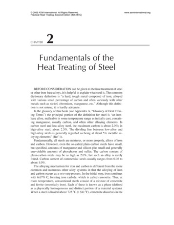
A LAYMAN’S EXPLANATION OF THE ROLE OF IT RACKS IN COOLING YOUR DATA CENTERIn this graph, you will see how the resistance (impedance) increases(exponentially) as more air is passed through any of the restrictions considered.The red line represents a typical server or fan response. As less backpressure(impedance) is applied to it, it produces a greater flow rate. The intersection of itwith any of the impedance curves would represent the effect of the impedance onthe flow rate for the server. In this case, if you close one door there would beabout 34.5 CFM passing through the system. If you closed both doors and added acable arm, the system flow rate would drop to about 34 CFM. Two closed doorsand the cable management arm would cause a decrease in the server flow rate toabout 33 CFM.IT vendors take into account typical external resistances that might be encoun‐tered by equipment and make sure that net flow rates still produce acceptabletemperatures.Think of it as nothing more than an added pinch point. Air traveling through therack squeezes through many restrictions between the front and the rear. Itsqueezes through door perforations, the front bezel vents (if present), the frontchassis vents, very restrictive heat sinks, rear chassis vents, and eventually therear door perforations. It is the sum of these restrictions, including a cable arm,which establishes the resulting flow rate. Even something as apparently restrictiveas a full cable management arm is but an incremental resistance when you con‐sider flow through the entire rack. It’s kind of like a kink in your garden hose.After you straighten it out, you might still see a noticeable indention. It probablyis slowing the flow down a little bit. But other factors probably play a heavier rolein deciding what the ultimate flow rate is‐ other factors like hose length, hose di‐ameter (I’ll never let my wife buy another ½” hose), what kind of sprinkler, etc.That kink is just one resistance of many contributing to the resulting flow.JUNE 20097
A LAYMAN’S EXPLANATION OF THE ROLE OF IT RACKS IN COOLING YOUR DATA CENTERIn summary, for anyone concerned about the thermal effect of a cable arm, theyshould be equally concerned about closing their front and rear doors. Our testingconcludes there is a slight internal component temperature rise due to all of therack resistances: front door, rear door, and cable arm. This added resistanceslows the air down slightly, 6% (half due to the cable arm), but this is expected andshould be of no concern relative to the thermal or compute performance of the ITequipment. The decision to use a cable arm should be made on the basis of ser‐viceability. Is it needed to provide a service loop when extending the equipmentfor component replacement? If you are a “rip and replace” shop, you probablydon’t need one; why pay for it? But if you do service in the rack, you should notconcern yourself over the minimal thermal impact associated with a cable arm.Results similar to the Dell testing may also be seen in tests published from HP(Rubenstein, B (2008). “Cable Management Arm Airflow Impedance Study”).For more information, please consider the following links:Rack Infrastructure Effects on Thermal Performance of a ss solutions whitepapers en/Documents al‐performance‐of‐a‐server.pdf.aspxJUNE 20098
A LAYMAN'S EXPLANATION OF THE ROLE OF IT RACKS IN COOLING YOUR DATA CENTER JUNE 2009 3 This model was created for purposes of cost justification for installing a blanking panel. A rack is loaded with forty current day 1U servers of typical configuration. 68 degree