Transcription
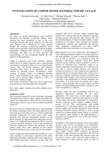
As originally published in the SMTA ProceedingsINVESTIGATION OF COPPER SINTER MATERIAL FOR DIE ATTACHChristian Schwarzer 1; Ly May Chew 2; Michael Schnepf 1; Thomas Stoll 3;Jörg Franke 3; Michael Kaloudis 11UAS Aschaffenburg, Aschaffenburg, Germany2Heraeus Deutschland GmbH & Co.KG, Hanau, Germany3Friedrich-Alexander-University FAPS, Nürnberg, GermanyABSTRACTDie attach on power semiconductor using lead-freetechnology has attracted considerable interest. Silversintering has been considered as one of the mostpromising lead-free die attach solutions over the pastyears. Pressure silver sintering by far offers superiorthermal and electrical conductivity properties whichenables power electronics applications to operate at highertemperature. Although silver sintering is a promisingtechnology, the high cost of silver increases themanufacturing cost and consequently impedes the wideadoption of this technology.Copper is commonly used in the electronics industrymainly due to its unique properties such as good thermaland electrical conductivity. Hence, it is not surprising thatrecently there are several academic and industrialresearches using copper as an alternative die attachmaterial for sintering process. Nevertheless, coppersintering is usually requires an additional reducingprocess using hazardous gases such as hydrogen andformic acid to prevent copper oxidation as well as toincrease the bonding strength.In this study, we develop a safe-to-use micro-copper sinterpaste for pressure sintering under inert atmosphere.Key words: copper sintering, die attach material, powerelectronicsINTRODUCTIONThe increasing demand for power electronics packagingwith higher power density, higher voltage and smaller sizerequires the replacement of silicon dies by wide band gapsemiconductor devices such as silicon carbide and galliumnitride [1].Because of their low melting temperature, solder materialsare facing a challenge to use as die attach materials for thewide band gap semiconductor devices which require highoperating temperature. In recent years, silver sintermaterials have attracted considerable attention as dieattach materials for high temperature application not onlybecause of its high melting temperature (961 C) but alsoit possess excellent properties such as high thermal andelectrical conductivity. Besides the advantage of highmelting point, silver sinter materials do not containhazardous substances such as lead, mercury and cadmium.Several studies have demonstrated the feasibility of silversinter materials as interconnect materials for die attachapplication and further confirmed silver sinter materials ashigh reliable interconnect materials via their long termreliability tests [2–4]. Previous studies revealed highreliable silver sintered joint can be obtained by pressuresintering process with relatively short process time andthe increased lifetime of sintered modules enable a cleanerproduction [5–10]. Silver sinter materials are currentlycommercially available and additionally the pressuresinter equipment manufactured for high volumeproduction have been increasing over the past years.High material cost of silver hinders the wide adoption ofsilver sintering technology despite of its unique propertiesand high reliability. In order to keep the manufacturingcost as low as possible, it is essential to look foralternative interconnect materials which have lowermaterial cost but relatively similar properties to silver. Anumber of researches have considered copper as anattractive alternative material because of its relatively lowcost and it possess similar thermal and electricalconductivity to silver [11–16]. Copper can be referred as astandard material in electrical engineering, which can befound as a conductor material in electronic assemblies andespecially cables. Copper is also used in power electronicsespecially in the metallization of ceramic substrates andlead frames. It is well known for decades that copperpossess several strengths such as good current carryingcapacity and high melting point but also weaknesses suchas the susceptibility to oxidation.Recently, copper has been scientifically studied as analternative interconnect material for die attachapplications. The main focus of the studies is usingcopper-nano particles, which has been reported to be ableto form sinter joint at low temperatures by pressurelesssintering, however, it often requires complex synthesisprocess [17–22]. The environmental and healthconsequences of nanoscale particles are often part ofintensive public and scientific discussions which led theEuropean Chemicals Agency (ECHA) to form a groupseeking for common ground among experts on scientificand technical issues relating to the implementation ofregulations for nanomaterials such as Biocidal ProductsRegulation (BPR).In addition to the nanoscale materials, micro-scale copperpowder is also actively investigated as an interconnectmaterial. In the case of micro-scale material, a pressuresintering method is often applied. The die attachment ondirect copper bonded (DCB) substrates by pressuresintering of copper particles was reported in 2012 [23]. Inthis study, it has been reported that reduction steps arenecessary to remove oxides from the copper surface byusing hydrogen or other reducing agents in order toProceedings of SMTA International, Oct. 14 - 18, 2018, Rosemont, IL, USA
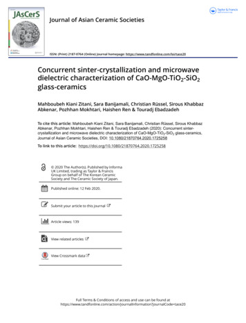
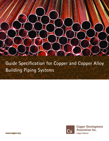
connect the electronic components to the substrate usingcopper particles in the sintering process.Recent results show that for a pressureless sinteringprocess, reduction of copper oxide under a component isusually insufficient to create an interconnection joint withhigh bonding strength [24]. Besides the concentration ofthe reduction agent, the sintering temperature also play animportant role in determining the bonding strength. [25].The use of copper as the die attach material still facingmany challenges such as copper oxidation and long termreliability and additionally the introduction of reductionprocesses is challenging for high volume productionenvironment as investment in suitable equipment andspecial safety handling are required.The aim of this study is to investigate the feasibility ofusing copper as an interconnect material without a priorapplication of a reduction process.EXPERIMENTALIn this study, different copper powders were used toprepare copper pastes. The copper pastes were then usedto sinter copper strips and also used as interconnectmaterials to attach two copper foils as well as to bond Sidies on DCB substrates. To evaluate the copper pastes,several tests were performed on the samples and the detailare described in the following sections.Copper pasteCopper pastes used in this study were made by mixingcopper powder with organic solvents. Different copperpowders were evaluated in this study. One sphericalshaped copper powder and two flake-shaped powderswere sourced for the experimental tests as can be seen inFigure 1. The particle size D50 of the flake-shapedpowder 1 and 2 is specified as 3.6 μm and 3.3 μm,respectively. The two copper flakes types differ inparticular by the coating around the powders.remove the organic solvent. After drying, the sampleswere pressed at room temperature and 573 K for 3 minwith a pressure of 10 MPa under N 2 atmosphere. Duringthe sintering process, the copper strips were covered by apolytetrafluoroethylene (PTFE) foil to protect the pressstamp.After pressing, the copper strips were removed from theceramic substrate and examined by optical microscopeand SEM. After metallurgical pretreatment, Crosssectional pictures were evaluated using Hitachi TM-1000scanning electron microscope (SEM) coupled with Burkerenergy dispersive X-ray spectroscopy (EDX).Specimen for tensile shear testCopper foils were cleaned with citric acid to reduce theoxide layer which may have formed during storage. Thecopper paste was printed on the copper foil using a stencilwith a dimension of 10 mm x 10 mm and a thickness of200 µm. The printed paste was then dried at 353 K underair atmosphere. Afterward, a second copper foil wasplaced on the dried copper paste and the assembly waspressed at 573K under N 2 atmosphere with a pressure of10 MPa.For characterization of the powder solidification, thetensile shear strength of the bonding layer was measured.For this investigation, two copper foils with a dimensionof 40 mm x 10 mm x 1 mm were attached using thecopper pastes by pressure assisted process (Figure 2.a)and subsequently conducted destructive tests usingShimadzu EZ-L tensile testing machine (Figure 3a).a)b)a)b)c)Figure 1. SEM images of a) spherical copper powder, b)copper flake 1 and c) copper flake 2 with 2000xmagnificationFigure 2. a) Schematic diagram of sample prepared forthe tensile shear test, b) bonded copper foils sampleThree copper pastes with a metal content of about 75 wt%were prepared by mixing the micro-scale copper powdersshown in Figure 1 with organic solvents and subsequentlythe pastes were milled using a three-roll mill to ensure abetter dispersion of copper powders in the paste.Sintering of Copper stripsCopper strips were prepared by printed copper paste onAl 2 O 3 ceramic substrates using stencils with a thicknessof 200 μm. The printed copper strips with a dimension of40 mm x 10 mm were dried at 353 K in an oven toProceedings of SMTA International, Oct. 14 - 18, 2018, Rosemont, IL, USA
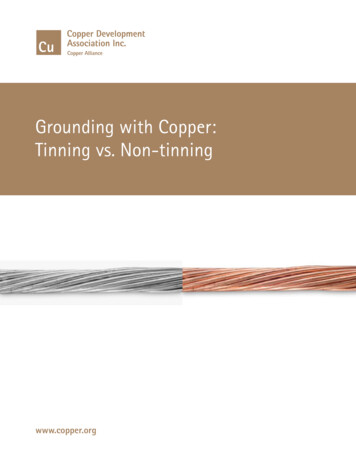
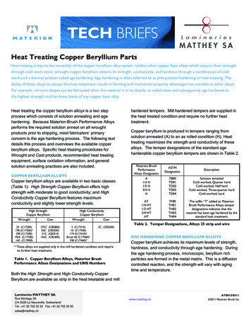
b)b)a)Figure 4b. Die attached on DCB substrates with a) silvermetallization and b) bare copper surface using copperpastesa)Figure 3. a) Tensile testing machine and b) schematicdiagram of the tensile testThe assembled test specimens (Figure 2.b) were clampedvertically in the tensile testing machine (Figure 3a) andthe samples were loaded until breakage at a constant testspeed of 1 mm / min. The shear force was calculated fromthe maximum measured force and the area of the printedpaste deposit. After tensile test, the failure mode wasobserved by optical microscope.The measured tensile shear strength and the fracturepatterns are used to evaluate the interconnection betweenthe copper sintered layer and the surface of the copperfoil.The bonding strength of the copper layer wascharacterized by means of a destructive die shear test. Dieshear measurement is a standard test method to determineshear strength of bonding materials in accordance withMIL-STD-883. It is based on a measure of force appliedto a semiconductor die attached to a substrate usingcopper paste as a bonding material. Figure 5 shows theschematic diagram of die shear test. A Nordson Dage4000 plus machine (Figure 6) was used to measure theshear strength of assembled samples.Figure 5. Schematic diagram of die shear testPreperation of Die attach samplesThe copper pastes produced in this study were also usedas interconnect material to attach dies on DCB substrates.In addition to the previous three copper pastes, a pastewith a mixture of the two flake-shaped powders (copperflake 1 and copper flake 2) with a ratio of 1:1 wasprepared and used as interconnect material.Figure 4a. Schematic diagram of the die attach samplesThe assembly process for the die attach samples is basedon the methods and common procedures of silver sinteredmaterials. The copper sinter paste was printed on thesubstrate using a stencil with a thickness of 200 µm andthen dried at 353 K in an oven for 30 min to remove theorganic solvents. Subsequently, Ag metallized silicon dieswith a size of 4 mm x 4 mm were attached to the driedcopper paste with a placement force of 2000 g for 4seconds. Subsequently, the sample was pressed at 573 Kwith a pressure of 15 MPa under N 2 atmosphere for 3min.Figure 6. Die shear machine with test specimenAfter the die shear test, the failure modes of the sinteredlayer were evaluated by optical microscope and SEM.RESULTSInvestigation of Copper stripsFigure 7 a) and b) show the copper strips after pressing atroom temperature under N 2 atmosphere for 3 min. Partsof the copper strips were peeled off during the removal ofthe PTFE foil. After pressing at room temperature,powder solidification could neither be detected for thespherical nor the flake-shaped copper powder.Proceedings of SMTA International, Oct. 14 - 18, 2018, Rosemont, IL, USA
The process temperature of 573 K showed heterogeneousresults. After pressing at 573 K, the copper strip consistsof spherical copper powder (Figure 7 c) was mainlyremoved together with the PTFE foil. The fracturebehavior of the spherical copper powder indicates that nocompound was formed. On the other hand, the flakeshaped particles (Figure 7 d) solidify into a copper stripwithout any fragments or visible defects of the copperlayer. Some of the copper strips consist of the flakeshaped particles, a dark discoloration was observed partlyat the edges indicating the oxidation of the copper surface.Simple mechanical processing shows that the darkdiscoloration of the copper takes place only superficially.a)b)d)c)Figure 7. After pressing at room temperature, copperstrips with a) spherical powder and b) copper flake 2.After pressing at 573 K under N 2 atmosphere, copperstrips with c) spherical powder and d) copper flake 2.Figure 8. SEM images of the cross section of a copperstripe with copper flake 1 with 1000x magnification andenlarged with 5000x magnificationFigure 9 shows the SEM images with a 1000xmagnification of the cross section of a copper stripe ofcopper flake 2 produced at 573 K under N 2 atmosphereand additionally enlarged detail with a magnification of5000x. It can be seen that the copper layer appears to bemore compact with less and smaller pores and in contrastto Flake 1, the contour of the copper flakes 2 is lessnoticeable.The results above show that it was not possible to producecopper strips with spherical-shaped copper powder as wellas by pressing at room temperature. As a result, theevaluation of bonding strength was only conducted for thecopper strips consist of the two flake-shaped copperpowders after pressing at 573 K.Figure 8 shows the SEM images with a 1000xmagnification of the cross sections of a copper stripeconsisting of copper flake 1 produced at 573 K under N 2atmosphere with an additionally enlarged detail with amagnification of 5000x. The image shows that copperflake 1 still has distinct pores in the layer, the contour andorientation of the individual copper flakes can be seenclearly as well.Figure 9. SEM images of the cross section of a copperstripe with copper flake 2 with 1000x magnification andenlarged detail with 5000x magnificationResults of Tensile Shear TestAfter pressing, the copper layer between the copper foilsresulted in 75 µm thickness. The results of the tensileshear test are shown in Figure 10. For the spherical copperpowder, no strength values could be determined, since allthe specimens were destroyed before or during handlingand clamping in the tensile testing machine. The copperflake 1 and 2 achieved different shear strength. 5 sampleswere sheared to generate an individual box plot. Figure 10Proceedings of SMTA International, Oct. 14 - 18, 2018, Rosemont, IL, USA
shows that copper flake 2 achieved an average shearstrength of 3.2 N/mm² which is higher than copper flake 1with an average shear strength of 1.2 N/mm².Shear test of Cu-foil Cu powder Cu-foil in N/mm²5N/mm²4Figure 12. Fracture of the joints with spherical powder onthe copper opperFigure 10. Tensile shear strength values of the connectedcopper foilsIn order to compare with silver sintered material, tensileshear measurements were also performed on the samplesusing commercially available silver sintered material asinterconnect material. The results reveal that the silversintered material achieved an average shear strength of 9.8N/mm², which is higher than the shear strength achievedby the samples prepared by copper material.Microscope images (Figure 13) further confirm the pastesconsist of flake-shaped copper powder achieved acohesive failure mode. The images demonstrate that thefailure pattern of the paste consists of flake-shaped copperpowder (Figure 13a) and the commercially available silversintered material (Figure 13b) are relatively similar wherethe copper layer can be found on the unprinted copperfoil.In addition to the fracture images, the microscope imageson some samples show a darker discoloration of thecopper layer (Figure 13a). The sign of oxidation can befound mostly on the edges of the bonding layer and wasnot observed at the same area in each sample.a)Figure 11 and 12 show the fracture patterns of the copperfoil after the tensile shear test. The optical images of thefracture patterns illustrate a cohesive break in the copperlayer was obtained for the pastes consist of the flakeshaped copper powders where the copper layers can befound on both copper foils (Figure 11a & b). In addition,discoloration in the copper layer was observed from theoptical images demonstrating the oxidation of copperlayer. In contrast, adhesive break was obtained for thepaste consists of the spherical-shaped powder wherecopper layer was only found on the printed copper foil(Figure 12).a)b)Figure 11. Fracture of the joints with a) spherical powderb) copper flake 1 and c) copper flake 2 on the copper foilb)Figure 13. Microscope images of the residues of pasteswith a) copper flake 2 and b) silver sinter material on theunprinted copper foilThis observation suggests that the oxidation does not startfrom the center of bonding layer but it occurs from theoutside. Presumably, the oxidation caused by theremaining oxygen content during the sintering process orduring the cooling process without continuous supply ofnitrogen.Results of Die Shear TestProceedings of SMTA International, Oct. 14 - 18, 2018, Rosemont, IL, USA
The die shear strength was conducted for the die attachsamples to evaluate the bonding strength of coppersintered joint. It was not possible to measure die shearstrength for the samples assembled by the paste withspherical copper powder because the silicon dies peeledoff immediately after pressing at 573 K. This observationillustrates that the copper paste made by spherical copperpowder is not able to create interconnection joint betweendie and substrate.surface material of DCB substrate becomes visible (areaA shown in Figure 15a).The results of the shear strength measurement are shownin a box plot diagram (Figure 14). 12 dies were shearedoff for each paste to generate an individual box plot. It canbe seen from Figure 14 that copper flake 2 achieved thehighest die shear strength ( 30 N/mm²) among the threecopper pastes, whereas, copper flake 1 obtained the lowestdie shear strength ( 10 N/mm²). The paste with themixture of copper flakes 1 and copper flake 2 achievedthe average die shear strength above 15 N/mm². Theresults indicate that the interconnection joint created bycopper flake 1 is poorer than that by copper flake 2. Thelower die shear strength of the paste with the mixture ofcopper flakes might be attributed to the poor adhesion ofcopper flake 1. A similar trend was observed for all 3copper pastes in which there is no significant difference inthe average die shear strength for Ag metallized and barecopper substrates.a)b)Figure 15. Die shear failure mode of a) Ag metallizedsubstrate b) bare copper substrateShear strength [N/mm²]Die Shear Test5037,330Paste34,220,9200Figure 16 illustrates the SEM image of the Ag metallizedsubstrate after die shear test. The areas marked with A andB in Figure 16 are the silver metallization and theremaining copper joint, respectively.With a magnification of 1000x, the image shows that evenin the corners, where the metallization of the substrateoptically emerges, adhesion of copper to the surface isstill observed.Process: 3min 573K 15MPa N2 4*4 mm² lake2 50%CF1 50%CF2Figure 14. Boxplot of shear strength for silver and copperDCB substrateThe material contrast of the silver metallized surface andthe copper die attach material facilitates the interpretationof the fracture patterns by light microscope or SEM andthe detection of copper by EDX. For the samples oncopper substrate, the interpretation is therefore moredifficult.After die shear tests, the substrates sintered by the pasteconsists of copper flake 2 were examined by opticalmicroscope and SEM. The results reveal that cohesivebreak in the copper layer were obtained and thisobservation explains the high shear strength achieved bythe paste consists of copper flake 2.Figure 15 shows the die shear failure mode and it can beseen that mostly cohesive break in the copper layer wasobtained where a copper layer can be found on the diebackside and also on the substrates surface after die sheartests. Only in some corners of the die attach area theFigure 16. SEM image with a magnification of 1000x ofthe fracture mode of silver metallized substrate after dieshear testIn addition, holes on the surface of Ag metallized DCBsubstrate can be seen from the SEM image (area Cmarked in Figure 16). These defects could not be foundon the surface of the original Ag metallized DCBsubstrate before sintering. The holes were only observedon the Ag metallized DCB substrate sintered by the pasteconsists of copper flake 2. It is believe that the Agmetallized layer was peeled off during die shear testwhich created the holes on the substrate surface.Presumably, this phenomenon is caused by the strongbonding strength of copper joint on the Ag metallizedDCB substrate.CONCLUSIONIn summary, 3 different copper powders were tested fortheir feasibility to use as die attach material for pressuresintering process without prior treatment with reducingagents such as hydrogen or formic acid. The resultsillustrate that spherical-shaped copper powder was notable to create copper joints by pressure sintering processProceedings of SMTA International, Oct. 14 - 18, 2018, Rosemont, IL, USA
at 573 K with a pressure of 10 MPa for 3 min under N 2atmosphere. In contrast, it was possible to create copperjoints by pressure sintering process using flake-shapedcopper powders. The shear strength and the failure moderesults show that copper flake 2 created stronger copperjoint than copper flake 1. This study demonstrate that it isfeasible to use copper paste as interconnect material fordie attach application by pressure sintering process, evenwithout reducing agents.Nevertheless, this research is still ongoing and furtherimprovements are needed. Copper oxidation on the outeredges of copper strips was observed and it is highly likelythat a fluctuating or insufficient nitrogen flow duringsintering or cooling process led to the copper oxidation.As a result, an improvement of the nitrogen supply will bepart of our further investigation. Additionally, as can beseen from the results that different copper powdersachieved different bonding strength of copper joint.Hence, sintering behavior of different copper powderswill be further investigated in our study.Furthermore many investigations on mechanical andelectrical properties of sintered copper material as well asstudies on environmental simulations by aging will bedone to evaluate copper sintering as a die attachtechnology.ACKNOWLEDEGMENTThe authors would like to thank Michael Jörger andWolfgang Schmitt from Heraeus Electronics for theirsuperb scientific guidance and Timo Schreck frommaterials technology lab of UAS Aschaffenburg for thehelpful technical support.REFERENCES[1]K. S. Siow, “Are Sintered Silver Joints Ready forUse as Interconnect Material in MicroelectronicPackaging?,” Journal of Elec Materi, vol. 43, no. 4, pp.947–961, 2014.[2]C. Weber, M. Hutter, S. Schmitz, and K.-D.Lang, “Dependency of the porosity and the layer thicknesson the reliability of Ag sintered joints during active powercycling,” pp. 1866–1873.[3]R. Dudek et al., “Investigations on PowerCycling Induced Fatigue Failure of IGBTs with SilverSintered Interconnects,” in European MicroelectronicsPackaging Conference 2015.[4]K. S. Siow and Y. T. Lin, “Identifying theDevelopment State of Sintered Silver (Ag) as a BondingMaterial in the Microelectronic Packaging Via a PatentLandscape Study,” J. Electron. Packag, vol. 138, no. 2, p.20804, 2016.[5]M. Beierlein and M. Kaloudis, “Silber-Sintern inder Leistungselektronik,” Aschaffenburg, Oct. 24 2013.[6]M. Beierlein and M. Kaloudis, “Evaluation ofPressureless Silver Sintered High Power SemiconductorDevices by Measurement of thermal Impedance,”Dresden, Oct. 8 2013.[7]L. Braunwarth, S. Amrhein, T. Schreck, and M.Kaloudis, “Ecological comparison of soldering andsintering as die-attach technologies in power electronics,”Journal of Cleaner Production, no. 102, pp. 408–417,2015.[8]L. M. Chew, W. Schmitt, C. Schwarzer, and J.Nachreiner, “Micro-Silver Sinter Paste Developed forPressure Sintering on Bare Cu Surfaces under Air or InertAtmosphere,” in 2018 IEEE 68th Electronic Componentsand Technology Conference (ECTC), San Diego, CA,USA, 2018, pp. 323–330.[9]W. Schmitt and L. M. Chew, “Silver Sinter Pastefor SiC Bonding with Improved Mechanical Properties,”in 2017 IEEE 67th Electronic Components andTechnology Conference (ECTC), Orlando, FL, USA,2017, pp. 1560–1565.[10]T. Krebs et al., “Breakthrough in PowerElectronics Reliability – New Die Attach and WireBonding Materials,” in Sixty Third ElectronicComponents & Technology Conference (ECTC): May 2831, 2013, 2013.[11]T. Suzuki et al., “Thermal cycling lifetimeestimation of sintered metal die attachment,” in 2016International Conference on Electronics Packaging(ICEP), 2016, pp. 400–404.[12]H. Nakako et al., “Sintering Copper Die-BondingPaste Curable Under PressurelessConditions,” in PCIMEurope 2017; International Exhibition and Conference forPower Electronics, Intelligent Motion, Renewable Energyand Energy Management, 2017, pp. 1–5.[13]T. Suzuki et al., “Macro- and Micro-DeformationBehavior of Sintered-Copper Die-Attach Material,” IEEETrans. Device Mater. Relib., vol. 18, no. 1, pp. 54–63,2018.[14]T. Suzuki et al., “Thermal cycling lifetimeestimation of sintered metal die attachment,” in 2016International Conference on Electronics Packaging(ICEP), Hokkaido, Japan, pp. 400–404.[15]H. Nakako et al., “"Sintering Cu Die-bondingPaste with High Thermal Conductivity and High BondingReliability",” Hitachi Chemical Technical Report No. 60.[16]Hideo Nakako, Dai Ishikawa, Chie Sugama,Yuki Kawana, Motohiro Negishi, Yoshinori Ejiri, “HighlyReliable Package Bonding with Copper Sintering Paste,”in SMTA International Conference Proceedings, 2017.[17]J. Zürcher et al., “Nanoparticle assembly andsintering towards all-copper flip chip interconnects,” in2015 IEEE 65th Electronic Components and TechnologyConference (ECTC), 2015, pp. 1115–1121.[18]Jonas Zürcher, Kerry Yu, Gerd Schlottig, MarioBaum, Maaike M. Visser Taklo, Bernhard Wunderle,Piotr Warszynski, Thomas Brunschwiler, “NanoparticleAssembly and Sintering Towards All-Copper Flip ChipInterconnects: 26-29 May 2015, San Diego, CA, USA,” inIEEE 65th Electronic Components & TechnologyConference proceedings.[19]Y. Huang et al., “Rapid sintering of coppernanopaste by pulse current for power electronicspackaging,” in 2017 18th International Conference onElectronic Packaging Technology (ICEPT), Harbin,China, 2017, pp. 561–564.[20]B. H. Lee, M. Z. Ng, A. A. Zinn, and C. L. Gan,“Application of copper nanoparticles as die attachment forhigh power LED,” in 2015 IEEE 17th ElectronicsPackaging and Technology Conference (EPTC), 2015, pp.1–5.[21]A. A. Zinn, R. M. Stoltenberg, J. Chang, Y.Tseng, and S. M. Clark, “Nanocopper as a solderingProceedings of SMTA International, Oct. 14 - 18, 2018, Rosemont, IL, USA
alternative: Solder-free assembly,” in 2016 IEEE 16thInternational Conference on Nanotechnology (IEEENANO), 2016, pp. 367–370.[22]A. A. Zinn et al., “A novel nanocopper-basedadvanced packaging material,” in 2016 IEEE 18thElectronics Packaging Technology Conference (EPTC),2016, pp. 1–6.[23]J. Kähler et al., “Sintering of Copper Particles forDie Attach,” IEEE Trans. Compon., Packag. Manufact.Technol., vol. 2, no. 10, pp. 1587–1591, 2012.[24]A. Hanss, M. Schmid, S. K. Bhogaraju, F. Conti,and G. Elger, “Process development and reliability ofsintered high power chip size packages and flip chipLEDs,” in 2018 International Conference on ElectronicsPackaging and iMAPS All Asia Conference (ICEPIAAC), 2018, pp. 479–484.[25]H. Nakako et al., “Sintering Cu Bonding Paste:Cycle Reliability and Applications,” in PCIM Europe2018; International Exhibition and Conference for PowerElectronics, Intelligent Motion, Renewable Energy andEnergy Management, 2018, pp. 1–6.Proceedings of SMTA International, Oct. 14 - 18, 2018, Rosemont, IL, USA
Copper foils were cleaned with citric acid to reduce the oxide layer which may have formed during storage. The copper paste was printed on the copper foil using a stencil with a dimension of 10mm x 10 mm and a thickness of 200 µm. The printed paste was then dried at 353 K under air atmosphere. Afterward, a second copper foil was