Transcription
NASA/CR—2001-210903D950–10529–1Onboard Inert Gas Generation System/Onboard Oxygen Gas Generation System(OBIGGS/OBOGS) StudyPart I: Aircraft System RequirementsThomas L. Reynolds, Delbert B. Bailey,Daniel F. Lewinski, and Conrad M. RoseburgBoeing Commercial Airplanes Group, Seattle, WashingtonMay 2001
The NASA STI Program Office . . . in ProfileSince its founding, NASA has been dedicated tothe advancement of aeronautics and spacescience. The NASA Scientific and TechnicalInformation (STI) Program Office plays a key partin helping NASA maintain this important role. CONFERENCE PUBLICATION. Collectedpapers from scientific and technicalconferences, symposia, seminars, or othermeetings sponsored or cosponsored byNASA.The NASA STI Program Office is operated byLangley Research Center, the Lead Center forNASA’s scientific and technical information. TheNASA STI Program Office provides access to theNASA STI Database, the largest collection ofaeronautical and space science STI in the world.The Program Office is also NASA’s institutionalmechanism for disseminating the results of itsresearch and development activities. These resultsare published by NASA in the NASA STI ReportSeries, which includes the following report types: SPECIAL PUBLICATION. Scientific,technical, or historical information fromNASA programs, projects, and missions,often concerned with subjects havingsubstantial public interest. TECHNICAL TRANSLATION. Englishlanguage translations of foreign scientificand technical material pertinent to NASA’smission. TECHNICAL PUBLICATION. Reports ofcompleted research or a major significantphase of research that present the results ofNASA programs and include extensive dataor theoretical analysis. Includes compilationsof significant scientific and technical data andinformation deemed to be of continuingreference value. NASA’s counterpart of peerreviewed formal professional papers buthas less stringent limitations on manuscriptlength and extent of graphic presentations.TECHNICAL MEMORANDUM. Scientificand technical findings that are preliminary orof specialized interest, e.g., quick releasereports, working papers, and bibliographiesthat contain minimal annotation. Does notcontain extensive analysis.CONTRACTOR REPORT. Scientific andtechnical findings by NASA-sponsoredcontractors and grantees.Specialized services that complement the STIProgram Office’s diverse offerings includecreating custom thesauri, building customizeddata bases, organizing and publishing researchresults . . . even providing videos.For more information about the NASA STIProgram Office, see the following: Access the NASA STI Program Home Pageat http://www.sti.nasa.gov E-mail your question via the Internet tohelp@sti.nasa.gov Fax your question to the NASA AccessHelp Desk at 301–621–0134 Telephone the NASA Access Help Desk at301–621–0390 Write to:NASA Access Help DeskNASA Center for AeroSpace Information7121 Standard DriveHanover, MD 21076
NASA/CR—2001-210903D950–10529–1Onboard Inert Gas Generation System/Onboard Oxygen Gas Generation System(OBIGGS/OBOGS) StudyPart I: Aircraft System RequirementsThomas L. Reynolds, Delbert B. Bailey,Daniel F. Lewinski, and Conrad M. RoseburgBoeing Commercial Airplanes Group, Seattle, WashingtonPrepared under Contract NAS1–20341, Task Order 11National Aeronautics andSpace AdministrationGlenn Research CenterMay 2001
Trade names or manufacturers’ names are used in this report foridentification only. This usage does not constitute an officialendorsement, either expressed or implied, by the NationalAeronautics and Space Administration.Available fromNASA Center for Aerospace Information7121 Standard DriveHanover, MD 21076National Technical Information Service5285 Port Royal RoadSpringfield, VA 22100Available electronically at http://gltrs.grc.nasa.gov/GLTRS
CONTENTSPageLIST OF FIGURES. vLIST OF TABLES . ixACRONYMS AND ABBREVIATIONS. xi1.0 INTRODUCTION. . 11.1Purpose. 11.2Background. 11.3Technical Approach . 31.4Task Assignment and Work Authorization . 31.5Aircraft Models Selected for Study. 42.0 AIRPLANE REQUIREMENTS. . 92.1Regulatory Issues and Requirements . 92.2Design Requirements . 93.0 OXYGEN SYSTEMS . 113.1Crew Oxygen System Description. 113.1.1Crew Oxygen System Consumption . 163.1.2Crew Oxygen System Weight. 183.2Passenger Oxygen System Description. 183.2.1Chemical Supplemental Oxygen System . 233.2.2Gaseous Supplemental Oxygen System . 253.2.3Supplemental Oxygen Requirements . 273.2.4737 Oxygen Consumption Calculation . 293.2.4.1737 Oxygen System Weight. 323.2.5757 Oxygen Consumption Calculation . 323.2.5.1757 Oxygen System Weight. 363.2.6767 Oxygen Consumption Calculation . 363.2.6.1767 Oxygen System Weight. 403.2.7777 Oxygen Consumption Calculation . 403.2.7.1777 Oxygen System Weight. 443.2.8747 Oxygen Consumption Calculation . 443.2.8.1747 Oxygen System Weight. 483.2.9Oxygen Quality . 484.0 FIRE SUPPRESSION SYSTEMS. 514.1Cargo Compartment Fire Suppression Systems. 514.1.1Introduction. 514.1.2Scope . 514.1.3Design Overview. 524.1.3.1Cargo Smoke Detection Systems . 544.1.3.2Flight Deck Procedures for Cargo Fire . 564.1.3.3Cargo Fire Extinguishing Systems . 584.1.3.4Cargo Compartment Physical Parameters and FireHardening. 664.1.3.5Component Qualifications . 694.1.3.6System Certification . 73NASA/CR—2001-210903iii
4.1.3.7FAR Requirements. 744.1.3.8Airworthiness Directives . 744.1.3.9Advisory Circulars. 754.1.4Historical Development of Cargo Fire Protection Systems . 764.1.5Published Industry and FAA Cargo Fire Test Reports andDocuments . 804.1.6Nitrogen Cargo Fire Suppression Analysis . 844.1.6.1Nitrogen Knockdown With OBIGGS Inerting. 864.1.6.2Hybrid of Non-Nitrogen Knockdown With OBIGGSInerting . 954.2Electronic Equipment Bay Fire Protection. 1024.3Lavatory Extinguishing System Bottles . 1034.4Portable Hand-Held Extinguishers . 1045.0 FUEL SYSTEM, PROPULSION FIRE PROTECTION, AND FUELTANK INERTING REQUIREMENTS . 1055.1Introduction . 1055.1.1Scope . 1065.2Fire Protection Systems: General Requirements. 1075.2.1Typical Aircraft Safety Zones. 1075.2.2Fire Zones: Engine Nacelle and APU Bay. 1095.2.3Flammable Leakage Zone: Fire Protection Requirements . 1095.2.4Flammable Zone: Fuel Tanks. 1105.2.5Conclusions From the Fuel Tank Harmonization WorkingGroup . 1115.3. Fire Protection System Description: General . 1125.3.1Engine Nacelle Description. 1125.3.2APU Bay Description . 1235.4. Fuel Systems Description . 1245.5. Analysis. 131APPENDIX A: APPLICABLE FEDERAL AVIATION REGULATIONS AND ADVISORYCIRCULARS . 135REFERENCES . 161About the Authors . 163NASA/CR—2001-210903iv
LIST OF FIGURESPageFigure 1.0-1. Interior Configuration for the 737-800 (189 - All Economy Class) .5Figure 1.0-2. Interior Configuration for the 757-200 (235 - All Economy Class) .5Figure 1.0-3. Interior Configuration for the 767-300 (191 - Three-Class Configuration) 6Figure 1.0-4. Interior Configuration for the 777-300 (332 - Three-Class Configuration) 6Figure 1.0-5. Interior Configuration for the 747-400 (372 - Three-Class Configuration) 7Figure 3.0-1. Crew Oxygen System Schematic .12Figure 3.0-2. Typical Oxygen Gas Storage Cylinder.13Figure 3.0-3. Typical Crew Oxygen Cylinder Installation .14Figure 3.0-4. Flight Crew Quick-Donning Mask .15Figure 3.0-5. Passenger Oxygen Mask .20Figure 3.0-6. Aircraft Descent Profiles .21Figure 3.0-7. Oxygen System Schematic .22Figure 3.0-8. Passenger Service Unit With Chemical Oxygen Generator .24Figure 3.0-9. Typical Passenger Oxygen Cylinder Installation .26Figure 3.0-10. 737-800 Oxygen Consumption Rates .31Figure 3.0-11. 757-200 Oxygen Consumption Rates .35Figure 3.0-12. 767-300 Oxygen Consumption Rates .39Figure 3.0-13. 777-300 Oxygen Consumption Rates .43Figure 3.0-14. 747-400 Oxygen Consumption Rates .47Figure 3.0-15. Equivalent Altitudes .50Figure 4.0-1. 777 Airplane Lower Cargo Compartments .55Figure 4.0-2. Representative 777 Flow-Through Cargo Smoke Detection System .55Figure 4.0-3. Flight Deck Indication and Control of Cargo Fire Protection System.56Figure 4.0-4. 777 Cargo Fire Extinguishing System .58Figure 4.0-5. Isometric 777 Cargo Compartment Fire Extinguishing System .59Figure 4.0-6. Isometric 777 Cargo Fire Extinguishing System Bottle Installation.60NASA/CR—2001-210903v
Figure 4.0-7. 747-400 Lower Deck Cargo Compartment.61Figure 4.0-8. 747-400 Main Deck Cargo Compartment.62Figure 4.0-9. OBIGGS Cargo Fire Suppression System Schematic .88Figure 4.0-10. Nitrogen Knockdown With OBIGGS Control Volume Model .89Figure 4.0-11. Typical Total Nitrogen Fire Suppression Model.90Figure 4.0-12. Overall Nitrogen Fire Suppression System Requirements.92Figure 4.0-13. OBIGGS Control Volume Model (Non-Nitrogen Knockdown).97Figure 4.0-14. Typical Nitrogen Hybrid Fire Suppression System Model.98Figure 4.0-15. Typical E/E Bay (1).102Figure 4.0-16. Typical E/E Bay (2).103Figure 5.0-1. Fire Protection Zones (1).108Figure 5.0-2. Fire Protection Zones (2).108Figure 5.0-3. Fire Protection Outline.113Figure 5.0-4. Fire Protection Overview (1) .113Figure 5.0-5. Fire Protection Overview (2) .114Figure 5.0-6. Engine Fire and Overheat Detection .114Figure 5.0-7. Engine Fire and Overheat Detection and Warning (1) .115Figure 5.0-8. Engine Fire and Overheat Detection and Warning (2) .115Figure 5.0-9. Engine Fire and Overheat Detection and Warning (3) .116Figure 5.0-10. Engine Fire Extinguishing System (1).116Figure 5.0-11. Engine Fire Extinguishing.117Figure 5.0-12. Engine Fire Extinguisher .117Figure 5.0-13. APU Fire Detection and Warning (1) .118Figure 5.0-14. APU Fire Detection and Warning (2) .118Figure 5.0-15. APU Fire Detection and Warning (3) .119Figure 5.0-16. APU Fire Extinguishing (1) .119Figure 5.0-17. APU Fire Extinguishing (2) .120viNASA/CR—2001-210903
Figure 5.0-18. APU Fire Extinguishing (3) .120Figure 5.0-19. Wing Duct Leak Detection.121Figure 5.0-20. Wheel Well Fire and Duct Leak Detection (1) .121Figure 5.0-21. Wheel Well Fire and Duct Leak Detection (2) .122Figure 5.0-22. 747-400 Fuel System Performance.124Figure 5.0-23. 747-400F Fuel Systems .125Figure 5.0-24. 747-400 Fuel Tank Arrangement (1) .125Figure 5.0-25. 747-400 Fuel Tank Arrangement (2) .126Figure 5.0-26. 747-400 Fuel Tank Venting .126Figure 5.0-27. Wing Surge Tank Flame Arrester.127Figure 5.0-28. 747-400 Fuel Vent Float Valves .127Figure 5.0-29. Center and Wing Tank FQIS Components.128Figure 5.0-30. 747-400 Fueling System - General.128Figure 5.0-31. 747-400 Fueling System – CWT and HST (1).129Figure 5.0-32. 747-400 Fueling System – CWT and HST (2).129Figure 5.0-33. 747-400 Fueling System – CWT and HST (3).130Figure 5.0-34. 747-400 Refueling Valves .130Figure 5.0-35. 747-400 Engine Fuel Feed System .131Figure 5.0-36. Ullage Oxygen Versus OBIGGS Volume Added .132NASA/CR—2001-210903vii
LIST OF TABLESPageTable 3.0-1. Crew Oxygen System Weights for Study Aircraft . 18Table 3.0-2. Minimum Oxygen Required at Cabin Altitude . 28Table 3.0-3. 737-800 Oxygen Consumption Rate Calculations. 30Table 3.0-4. 757-200 Oxygen Consumption Rate Calculations. 34Table 3.0-5. 767-300 Oxygen Consumption Rate Calculations. 38Table 3.0-6. 777-300 Oxygen Consumption Rate Calculations. 42Table 3.0-7. 747-400 Oxygen Consumption Rate Calculations. 46Table 4.0-1. Cargo Compartment Classifications . 53Table 4.0-2. Cargo Fire Extinguishing Performance by Airplane Model . 64Table 4.0-3. Cargo Compartment Physical Parameters by Airplane Model(sheet 1 of 2) . 67Table 4.0-3. Cargo Compartment Physical Parameters by Airplane Model(sheet 2 of 2). 68Table 4.0-4. Operational and Nonoperational Environmental Temperature Limits . 71Table 4.0-5. Operational Pressure Altitude Limits . 71Table 4.0-6. Nitrogen Knockdown and 95% OBIGGS Analysis. 93Table 4.0-7. Nitrogen Knockdown and 98% OBIGGS Analysis . 94Table 4.0-8. OBIGGS Hybrid and 84% Nitrogen Fire Suppression . 99Table 4.0-9. OBIGGS Hybrid and 88% Nitrogen Fire Suppression . 100Table 4.0-10. OBIGGS Hybrid and 91% Nitrogen Fire Suppression . 101Table 5.0-1. Partial Summary of Fuel Tank Protection Systems on Military Aircraft. 106Table 5.0-2. Weights For Engine Nacelle Fire Extinguishing Systems . 123Table 5.0-3. Weights for APU Bay Fire Extinguishing Systems. 123NASA/CR—2001-210903ix
ACRONYMS AND SETOPSFAAFARFCUFHAFMEAFMRCFTHWGFQISHalon 1211Halon 1301HEIHSTIHRWGJAAJARLN2NASANSANTPDNTSBO2advisory circularsAirworthiness Directiveauxiliary power unitAviation Rulemaking Advisory Committeebuilt-in testCivil Air Regulationscarbon dioxidecenter wing fuel tanksDepartment of Transportationdesign requirements and objectivesElectronic equipmentengine indicating and crew alerting systemextended-range twin-engine operationsFederal Aviation AdministrationFederal Aviation Regulationflow control unitfunctional hazard assessmentfailure modes and effects analysisFactory Mutual Research CorporationFuel Tank Harmonization Working GroupFuel Quantity Indicating anehigh energy incendiaryHorizontal Stabilizer TankInternational Halon Replacement Working GroupJoint Aviation AuthoritiesJoint Aviation Requirementliquid nitrogenNational Aeronautics and Space Administrationnumerical safety analysisnormal temperature pressure dryNational Transportation and Safety BoardoxygenNASA/CR—2001-210903xi
OBIGGSOBOGSPSUsSAESCDSTPTALONTSOOnboard Inert Gas Generating SystemOnboard Oxygen Generating Systempersonal service unitstandardSociety of Automotive Engineersspecification control drawingsstandard temperature and pressureTotal Atmospheric Liquefaction of Oxygen and NitrogenTechnical Standard OrderNASA/CR—2001-210903xii
1.0 INTRODUCTION1.1PurposeThe purpose of this technology assessment is to define a multiphase research studyprogram investigating Onboard Inert Gas Generation Systems (OBIGGS) andOnboard Oxygen Generation Systems (OBOGS) that would identify current airplanesystems design and certification requirements (Subtask 1); explore state-of-the-arttechnology (Subtask 2); develop systems specifications (Subtask 3); and develop aninitial system design (Subtask 4). If feasible, consideration may be given to thedevelopment of a prototype laboratory test system that could potentially be used incommercial transport aircraft (Subtask 5). These systems should be capable ofproviding inert nitrogen gas for improved fire cargo compartment fire suppressionand fuel tank inerting and emergency oxygen for crew and passenger use.Subtask 1 of this research study, presented herein, defines current productionaircraft certification requirements and design objectives necessary to meetmandatory FAA certification requirements and Boeing design and performancespecifications. These requirements will be utilized for baseline comparisons forsubsequent OBIGGS/OBOGS application evaluations and assessments.1.2BackgroundOxygen systems, as they are currently designed for use on commercial transportaircraft, include passenger oxygen for use in the event of a sudden loss of cabinpressure (provided by either compressed oxygen or solid chemical oxygengenerators) and gaseous oxygen for use by the flight deck crew. There is alsoportable gaseous oxygen available for medical use and for protective breathingequipment. The use of oxygen on commercial aircraft, required by FAA regulations,does pose a potential fire safety hazard because of the extremely high gascombustion temperatures that can be produced by combustible materials burning ineither a pure or oxygen-enriched air environment. This is true of any oxygen systemin any environment. Passenger and crew oxygen requirements make up a significantpart of this contract study.NASA/CR—2001-2109031
In order to protect commercial passenger transport from the potential danger of inflight fires, especially those that can ignite in inaccessible areas during flight (cargocompartments, engine nacelles, and APU bays), fire protection systems and designtechniques have been developed to provide enhanced protection in all phases ofaircraft operations. Present-day suppression systems rely on sealed cargocompartments and the use of Halon 1301 to extinguish fires. There are currently nomandated requirements for inerting any compartments or sections of a commercialairplane. Continued production of Halon has been banned by internationalagreement because of its damaging effect on the stratospheric ozone layer. Thepossibility of using an OBIGGS to provide an alternative means of fire protection forexisting areas where Halon 1301 is currently used and inerting center wing tanks isa major part of this contract decreasingoxygenconcentration (inerting) are two different methods that can be employed for firecontainment or prevention. Chemical interference is currently obtained by injectingHalon gas into a sealed compartment to lower the oxygen (air) concentration toinhibit combustion. Halon effects fires in two ways: (1) it lowers the oxygenconcentration, and (2) lowers the combustion chemical reaction rate by combiningwith reactants. For long-duration protection, after initial “knockdown” applications ofHalon 1301, additional Halon is metered into the compartment to suppress orextinguish fires by chemical reactions in the fire zone. This technique has proven tobe highly effective against both open flame and deep-seated fires for lengthyperiods of time. Inerting an air volume to preclude combustion can be accomplishedby lowering the oxygen concentration by injecting an inert gas such as nitrogen orcarbon dioxide (gases that will neither support nor sustain combustion) to the pointwhereby combustion cannot occur.For the purpose of this contract study, two principle inerting applications wereconsidered in each of the aircraft models selected: cargo compartments (forward,aft, and bulk) and center wing fuel tanks (CWT). In the latter application, CWT fuelinerting, the military has demonstrated that in both live gun fire and laboratorytesting an ullage oxygen concentration of 9% or below will preclude catastrophicoverpressures in fuel tanks and dry bays.NASA/CR—2001-2109032
1.3Technical ApproachA technology that has been developed for generating oxygen and nitrogen gas fromair is gas separation. This can be accomplished by application of differenttechnologies such as by the use of a permeable membrane or pressure swingadsorption or by air distillation columns. Gas separation devices can separate anincoming stream of air into two exit streams with the composition of one beingnitrogen-enriched air (approximately 95% nitrogen and 5% oxygen) and the otherbeing oxygen-enriched air. These devices are currently in use in commercial trucksand ships to transport fresh fruit and vegetables in a nitrogen gas atmosphere topreserve freshness and for a longer storage life.There are some military aircraft that employ gas membranes for the generation ofnitrogen for fuel tank inerting and dry bays for fire and explosion protection andoxygen for crew breathing. The aircraft nomenclatures for these systems are:Onboard Inert Gas Generation System (OBIGGS) and Onboard Oxygen GenerationSystem (OBOGS).There are newer technologies in development that utilize distillation columns andcryogenic coolers to generate and store both liquid nitrogen and oxygen to meet therequirements for inerting and passenger and crew breathing. One such system nowin development is called TALON, an acronym for total atmospheric liquefaction ofoxygen and nitrogen. This type of system is capable of providing 99% pure oxygenand 96% pure nitrogen.Chemical generation of inert or oxygen gases is quite common as evidenced byonboard chemical oxygen generators in passenger aircraft, quick responseautomotive airbags, and special nitrogen generators used for dry bay fire protectionon some military aircraft and helicopters. These are pyrotechnic devices that aresquib activated to produce chemical reactions that generate the desired gases.These types of systems can be activated or deployed virtually instantaneously. Asan example, automotive airbags are inflated by chemical gas generators.1.4Task Assignment and Work AuthorizationThe authorization for Subtask 1 of this contract study was provided by NASAContract NAS1-20341, Task Assignment No. 11, Work Order 92M42, documentNASA/CR—2001-2109033
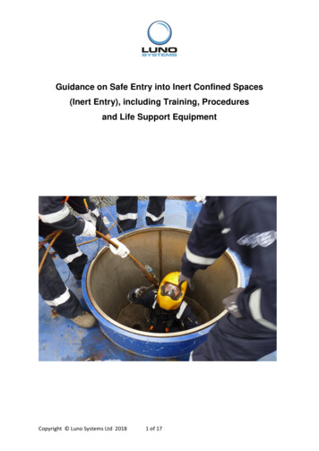
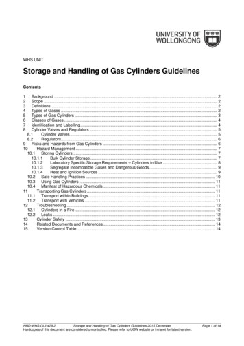
reference number 126 (NAS1-20341/SDE), dated June 7, 1999. The period ofperformance was stated to be June 15–December 15, 1999 and later revised toJune 15–June 30, 2000, with an escalation in costs. The total contract cost was 385,687 (cost plus no fees).1.5Aircraft Models Selected for StudyThis study used one configuration of each model of the Boeing family of aircraft incurrent production: the single-aisle 737-800 (fig. 1.0-1) and 757-200 (fig. 1.0-2) andthe twin-aisle 767-300 (fig. 1.0-3), 777-300 (fig. 1.0-4), and 747-400 (fig. 1.0-5). Inaddition, the 747-400 Combi was included because of its unique requirements foraccommodating both main deck cargo and passengers.NASA/CR—2001-2109034
NASA/CR—2001-2109035Figure 1.0-2. Interior Configuration for the 757-200 (235 - All Economy Class)Figure 1.0-1. Interior Configuration for the 737-800 (189 - All Economy Class)
NASA/CR—2001-2109036Figure 1.0-4. Interior Configuration for the 777-300 (332 - Three-Class Configuration)Figure 1.0-3. Interior Configuration for the 767-300 (191 - Three-Class Configuration)
Onboard Oxygen Gas Generation System (OBIGGS/OBOGS) Study Part I: Aircraft System Requirements NASA/CR—2001-210903 . the Lead Center for NASA's scientific and technical information. The . contractors and grantees. CONFERENCE PUBLICATION. Collected papers from scientific and technical