Transcription
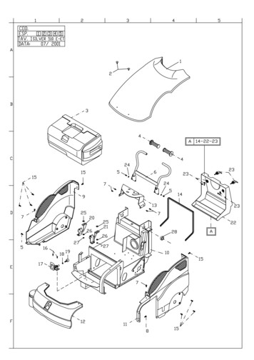
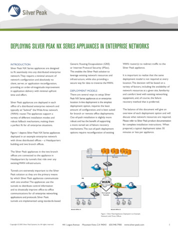
DEPLOYING SILVER PEAK NX SERIES APPLIANCES IN ENTERPRISE NETWORKSINTRODUCTIONSilver Peak NX Series appliances are designedto fit seamlessly into any distributed enterprisenetwork. They require a minimal amount ofnetwork configuration and absolutely noclient, server, or application reconfiguration,providing an order-of-magnitude improvementin application delivery with minimal upfronttime and effort.Silver Peak appliances are deployed in eachoffice of a distributed enterprise network andtypically sit “behind” the Wide Area network(WAN) router. The appliances support avariety of different installation modes androbust fallback mechanisms, making thema perfect fit for all enterprise situations.Figure 1 depicts Silver Peak NX Series appliancesdeployed in an example enterprise networkwith three distributed offices – a Headquartersbuilding and two branch offices.Generic Routing Encapsulation (GRE)or Internet Protocol Security (IPSec).This enables the Silver Peak solution toleverage existing network resources andinfrastructure, while also providing asecure way for data to traverse the WAN.DEPLOYMENT MODELSThere are several ways to setup SilverPeak NX Series appliances at an enterpriselocation. In-line deployment is the simplestdeployment option, requires the leastamount of configuration, and is best suitedfor branch or remote office deployments.Out-of-path installation is slightly morerobust and has the benefit of supportinga more varied set of failure recoverymechanisms. The out-of-path deploymentoptions require reconfiguration of existingThe Silver Peak appliances in the two branchoffices are connected to the appliance inHeadquarters by tunnels that ride over anyexisting WAN infrastructure.It is important to realize that the samedeployment model is not required at everylocation. The decision will be based on avariety of factors, including the availability ofnetwork resources at a given site, familiarityand comfort level with existing networkingequipment, and, of course, the failurerecovery method that is preferred.The balance of this document will give anoverview of each deployment option and willdiscuss what network resources are required.Please refer to Silver Peak product documentationfor complete installation instructions. Whenprepared, a typical deployment takes 30minutes or less per appliance.ServersStorageTunnels are extremely important to the SilverPeak solution as they are the primary meansby which Silver Peak appliances communicatewith one another. The appliances use thetunnels to distribute control informationand to drastically improve office-to-officecommunications for all enterprise networkingapplications and protocols. Silver Peaktunnels are implemented using standards-basedWAN router(s) to redirect traffic to theSilver Peak appliance.HQWANEncryptedTunnelsBranch Office ABranch Office BFigure 1 Silver Peak Appliances Deployed in an ExampleNetwork with Three OfficesCopyright 2005 Silver Peak Systems, Inc. All rights reserved.441 Logue AvenueMountain View, CA 94043650.940.7900www.silver-peak.com1
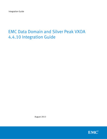
IN-LINEIn an in-line deployment the Silver Peakappliance is inserted in-line between theWAN router and the Ethernet switch onthe LAN side of the network (see Figure 2).In this mode, the appliance intercepts allpackets destined for the WAN.The applianceaccelerates traffic flows that match itsAccess Control Lists (ACLs); all other trafficpasses through the appliance unmodified.To install the appliance in this mode:1. Disconnect the Ethernet Local AreaNetwork (LAN) switch from theWAN router2. Connect the LAN interface of the appliance(see Appendix A for a description of theinterfaces on the NX Appliance) to theEthernet LAN switch3. Connect the WAN interface of the applianceto the WAN router4. No Ethernet LAN switch or WAN routerconfiguration modification is requiredLAN InterfaceIn the unlikely event that the appliancefails, the appliance will behave simply asa straight wire connecting the EthernetLAN switch directly to the WAN routerand traffic will continue to flow uninterrupted. It is important to note that, forthis failure recovery method to functioncorrectly, the Ethernet LAN switchand WAN router must have compatibleEthernet interface physical configurationsettings (speed and duplex).Tunnel Termination(Appliance IP Address)WANWAN InterfaceTunnelData FlowManagement Interface(Management IP Address)Figure 2 In-Line Deployment of Silver Peak ApplianceSUMMARYAppliance PlacementAppliance placed in-line between Ethernet LAN switch and WAN Router Appliance LAN interface connects to Ethernet LAN switch Appliance WAN interface connects to WAN routerFail-Safe BehaviorFails-To-Wire: The appliance behaves as straight wire between the Ethernet LAN switchand the WAN router in any failure scenario (hardware, software, power) IMPORTANT: Ensure that the Ethernet LAN switch and the WAN router havecompatible Ethernet interface physical configuration settings (speed and duplex settings).This is to ensure that traffic flows correctly if the Silver Peak appliance "Fails-to-wire"IP AddressesThis deployment model requires two IP addresses (on the same or separate subnets) Silver Peak Appliance IP Address (to originate and terminate tunnel) Silver Peak Management IP Address (for appliance configuration and management)Copyright 2005 Silver Peak Systems, Inc. All rights reserved.441 Logue AvenueMountain View, CA 94043650.940.7900www.silver-peak.com2
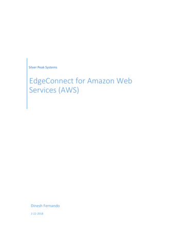
OUT-OF-PATH WITHPOLICY-BASED ROUTING REDIRECTIONAND FAILURE RECOVERYIn an out-of-path deployment, the Silver Peakappliance is not in the direct path of thenetwork traffic. As a result, a network trafficredirection technique is used to forwardtraffic to the appliance.If a spare interface is available on theWAN router, Policy-Based-Routing (PBR)redirection can be used to send traffic to theSilver Peak appliance. Policy Based Routing is acommon technique to redirect flows of trafficusing an ACL and a policy instead of normalrouting table lookups. Figure 3 shows a SilverPeak appliance installed in out-of-path modewith Policy-Based Routing redirection andfailure recovery. In this mode, the applianceintercepts only those packets that have beenredirected to it. The appliance acceleratestraffic flows that match its Access ControlLists (ACLs); all other traffic passes throughthe appliance unmodified.In the unlikely event that the appliancefails, the appliance will behave as openport and will not present a link-levelcarrier to the WAN router. The WANrouter will recognize that the linkassociated with the PBR is down andwill resume forwarding traffic normallyaccording to its routing tables.To install the appliance in this mode:1. Connect the WAN interface of the applianceto the WAN router’s available port2. Do NOT connect the LAN interfaceof the appliance3. Configure a PBR on the WAN router toredirect all traffic to be accelerated tothe Silver Peak Appliance IP AddressManagement Interface(Management IP Address)Tunnel Termination(Appliance IP Address)WAN InterfaceWANTunnelData FlowFigure 3 Out-of-path Deployment of Silver Peak Appliance withPolicy-Based Routing Redirection and Failure RecoverySUMMARYAppliance PlacementAppliance attached to available router interface Appliance WAN interface connects to available WAN interface Do not connect LAN interfaceFail-Safe BehaviorFails-Open:The appliance behaves as an unconnected port in all failure cases(hardware, software, power) The WAN router sees the link to the appliance go down, Policy BasedRouting fails, unicast routing forwards traffic normallyIP AddressesThis deployment model requires two IP addresses (on separate subnets) Silver Peak Appliance IP Address (to originate and terminate tunnel) Silver Peak Management IP Address (for appliance configuration and management)Configure PBR on WAN router Direct traffic from LAN (subnet/interface) destined for WAN to Silver Peak Appliance Do NOT enable this PBR on the interface to which the Silver Peak Appliance connectsCopyright 2005 Silver Peak Systems, Inc. All rights reserved.441 Logue AvenueMountain View, CA 94043650.940.7900www.silver-peak.com3
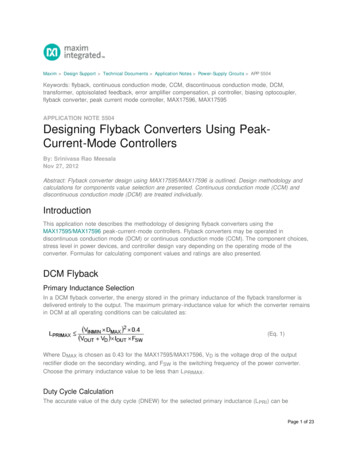
OUT-OF-PATH WITH VRRP PEERINGTO WAN ROUTERIn this scenario, like the last, the SilverPeak appliances are not connected inthe direct path of the network traffic.As a result, a network traffic redirectiontechnique is used to forward traffic tothe appliance in this scenario, as well.If a spare interface is not available onthe WAN router, then Policy BasedRouting (PBR) cannot be used to redirecttraffic to the Silver Peak appliance. In thiscase, the easiest way to direct traffic tothe appliance is to make the Silver Peakappliance the default gateway for all theclients and servers on the LAN side ofthe network. The easiest way to do this(which avoids reconfiguration of thehosts and servers) is to configure theIP Address of the Silver Peak applianceto be the same as the existing defaultgateway IP address.The appliance and the existing default gatewaynetwork element can share this IP addressusing Virtual Router Redundancy Protocol(VRRP). Assuming that this is the case and thatthe WAN router is the default gateway, Figure 4shows a Silver Peak appliance installed in outof-path mode with VRRP peering to the WANrouter. In this mode, the appliance intercepts allpackets destined for the WAN. The applianceaccelerates traffic flows that match its AccessControl Lists (ACLs); all other traffic passesthrough the appliance unmodified.Management Interface(Management IP Address)WAN InterfaceTo install the appliance in this mode:1. Connect the WAN interface of the applianceto interface on the Ethernet LAN switch2. Do NOT connect the LAN interfaceof the appliance3. Configure the WAN router and the SilverPeak appliance to share the LAN network’sdefault gateway IP address using VRRPIn the unlikely event that the appliance fails, theappliance will behave as open port. The WANrouter will assume the default gateway Virtual IPaddress and forward traffic normally.Tunnel Termination(Appliance IP Address)VRRPWANTunnelData FlowFigure 4 Out-of-path Silver Peak Appliancewith VRRP Peering to WAN RouterSUMMARYAppliance PlacementAppliance shares LAN segment with existing equipment Appliance WAN interface connects to Ethernet LAN switch Do not connect LAN interfaceFail-Safe BehaviorFails-Open The appliance behaves as unconnected port in all failure cases (hardware, software, power) WAN router assumes Virtual IP address and forwards traffic normallyIP AddressesThis deployment model requires three IP addresses Silver Peak Appliance IP Address (to originate and terminate tunnel) Silver Peak Management IP Address (for appliance configuration and management) Virtual IP Address (VIP) shared by Silver Peak appliance and the WAN routerThe VIP must be the default gateway for the clients and servers on the LAN subnet. Note:typically this would be the current default gateway to avoid client reconfigurationsThe Silver Peak Appliance must share the default gateway VIP with WAN router using VRRP The Silver Peak Appliance must be configured with higher priority andpreemption to ensure VRRP reverts to the applianceCopyright 2005 Silver Peak Systems, Inc. All rights reserved.441 Logue AvenueMountain View, CA 94043650.940.7900www.silver-peak.com4
OUT-OF-PATH WITH REDUNDANTSILVER PEAK APPLIANCESIn this scenario, the Silver Peak applianceis connected out of the direct path of thenetwork traffic, and a network trafficredirection technique is required. However,unlike the previous example, redundantSilver Peak appliances are used to ensurethat, in the unlikely event of an appliancefailure, applications continue to benefitfrom Silver Peak’s advanced applicationacceleration techniques.To install a pair of Silver Peak appliancesin this mode:1. Connect the WAN interface ofboth appliances to the WAN router’savailable interface2. Do NOT connect the LAN interfaceof either appliance3. Configure the Silver Peak appliancesto share a Silver Peak Virtual IPAddress via VRRPIn the unlikely event that the primaryappliance fails, it will behave as an openport. The backup appliance will assumethe Silver Peak Appliance Virtual IPaddress and accelerate traffic.VRRPTo deploy redundant Silver Peak appliances in an out-of-path configuration, aspare interface must be available on theWAN router (alternatively VLANs canbe deployed to achieve a similar logicaltopology). Policy-Based-Routing (PBR)redirection is used to send traffic to theredundant pair of Silver Peak appliances.Policy Based Routing is a common technique to redirect flows of traffic usingan ACL and a policy, instead of normalrouting table lookups. Figure 5 shows tworedundant Silver Peak appliances installedout-of-path with Policy-Based Routingredirection. In this mode, the appliancesintercept only those packets that havebeen redirected to them. The appliancesaccelerate traffic flows that match theirAccess Control Lists (ACLs); all other trafficpasses through the appliances unmodified.4. Configure the WAN router to redirectall traffic to be accelerated to theSilver Peak Appliance IP AddressWANFigure 5 Out-of-path Deployment ofRedundant Silver Peak AppliancesPrimary TunnelRedundant TunnelSUMMARYAppliance PlacementBoth appliances are attached to the same available interface via an Ethernet LAN switch Each appliance’s WAN interface connects to the Ethernet switch that is connected to the available WAN interface Do not connect LAN interface of either applianceFail-Safe BehaviorFails-Open The failed appliance behaves as unconnected port in all failure cases(hardware, software, power) The backup Silver Peak Appliance assumes the Silver Peak Appliance Virtual IP Address Remote appliances switch to the backup applianceIP AddressesThis deployment model requires five IP addresses on two separate subnetsOn the first subnet (the subnet of the available router interface) Each appliance needs a Silver Peak Appliance IP Address (to originate and terminate tunnels) The two appliances share one Silver Peak Appliance Virtual IP Address for VRRPOn the second subnet (the subnet of the LAN clients and servers) Each appliance needs a Silver Peak Management IP Address(for appliance configuration and management)Configure PBR on WAN router Direct traffic from LAN (subnet/interface) destined for WAN to Silver Peak Appliances’ Virtual IP Address Do NOT enable this PBR on the interface to which the Silver Peak Appliances connectCopyright 2005 Silver Peak Systems, Inc. All rights reserved.441 Logue AvenueMountain View, CA 94043650.940.7900www.silver-peak.com5
CONCLUSIONSilver Peak NX Series appliances areeasy to install, operate, and manage.There are several hardware variantsand configuration options available thatsatisfy diverse enterprise deploymentneeds from branch offices to fullyredundant data centers.Silver Peak delivers a true enterprisegrade solution for branch office infrastructure consolidation. Within minutes, enterprises can reap significantperformance benefits that improveapplication delivery while dramaticallyreducing the costs of IT operations.APPENDIX ANetwork InterfacesAll Silver Peak appliances have thesame set of four 10/100/1000 MbpsEthernet interfacess available at therear of the appliance. These interfacesare described in Table 1.ETHERNET INTERFACEFUNCTIONLANThis interface is intended for connection to the LAN side of the networkWANThis interface is intended for connection to the WAN side of the networkMgmt0This interface is intended for network access to the appliance'smanagement interfaces (the Web-based Appliance Manager and theCommand Line Interface). It is recommended that this interface isalways connected to the networkMgmt1This interface is intended for local access to the appliance’smanagement interfaces (the web-based Appliance Manager and theCommand Line Interface) with a laptop. This interface should neverbe connected to the networkTable 1 Silver Peak Appliance Network InterfacesEach Silver Peak appliance requires two IP addresses on thenetwork. These IP address are described in Table 2.IP ADDRESSFUNCTIONAppliance IP AddressThis IP address originates and terminates the tunnels used tointerconnect Silver Peak appliancesManagement IP AddressThis IP address is used for management and configuration of theSilver Peak appliance via the web-based Appliance Manager andCommand Line InterfaceTable 2 Silver Peak Appliance IP AddressesSilver Peak Systems, Inc.441 Logue AvenueMountain View, CA 94043650.940.7900www.silver-peak.comCopyright 2005 Silver Peak Systems, Inc. All rights reserved.6
This is to ensure that traffic flows correctly if the Silver Peak appliance "Fails-to-wire" This deployment model requires two IP addresses (on the same or separate subnets) Silver Peak Appliance IP Address (to originate and terminate tunnel) Silver Peak Management IP Address (for appliance configuration and management) WAN LANInterface