Transcription
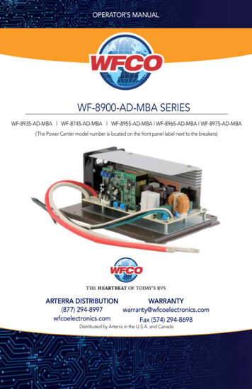
OPERATOR’S MANUALWF-8900-AD-MBA SERIESWF-8935-AD-MBA WF-8745-AD-MBA WF-8955-AD-MBA WF-8965-AD-MBA WF-8975-AD-MBA( The Power Center model number is located on the front panel label next to the breakers)WARRANTYARTERRA DISTRIBUTION(877) s.comFax (574) 294-8698Distributed by Arterra in the U.S.A. and Canada
TABLE OF CONTENTSSAFETY INFORMATION . 3GENERAL INFORMATIONAutomatic Cooling Fan . 3Over-Temperature Protection . 3Electronic Current Limiting . 4Short Circuit Protection . 4CIRCUIT PROTECTIONReverse Battery Protection . 4OPERATIONAL FEATURESAuto Detect . 5Three Stage Smart Charging . 5Two Stage Smart Charging . 7TROUBLESHOOTING INSTRUCTIONSConverter Output Voltage . 8Reverse Polarity Fuses . 8Troubleshooting Flow Chart . 9Replacing the MBA . 9GENERAL COMPLIANCE INFORMATIONAgency Listings . 11INSTALLATION INSTRUCTIONSMounting the MBA . 11WARRANTY INFORMATION . 12SPECIFICATIONS. 132
GENERAL INFORMATIONWF-8900-AD-MBA Series Main Board Assembly Safety FeaturesAUTOMATIC COOLING FANThe cooling fan in the WF-8900-AD Series Power Center is incremental and is controlled by thecurrent drawn out of the converter to the applied load. The on-board microprocessor increasesfan speed as the total load increases and decreases fan speed as the load decreases. Unliketraditional temperature-controlled fans, the load-controlled fan provides better componentcooling by avoiding temperature spikes which can lead to premature component failure.OVER-TEMPERATURE PROTECTIONIf the internal temperature of the converter exceeds a critical point, it will shut down. Thisprotects the unit from excessive heat that may damage sensitive components. The unit willrestart once the temperature inside has dropped.3
ELECTRONIC CURRENT LIMITINGIn the event that the output current exceeds the maximum rating for the WF-8900-AD SeriesPower Center converter, the output current will remain constant but the output voltage will beginto drop. If this occurs, the unit will recover once loads are reduced.SHORT-CIRCUIT PROTECTIONShould a short circuit occur in the RV, the WF-8900-AD Series Power Center converter will dropthe voltage output to zero volts. If the short-circuit condition is removed and no other faultconditions are detected, the converter will resume normal operation. However, short-circuit conditions are dangerous, and an RV will require inspection by a qualified service technician.CIRCUIT PROTECTIONWF-8900-AD-MBA Series Main Board Assembly Fuses and BreakersREVERSE BATTERY PROTECTIONThe WF-8900-AD-MBA Series Main Board Assembly will charge the 12-volt House battery ifinstalled. A battery DOES NOT have to be installed for WF-8900-AD-MBA Series Main BoardAssembly to operate. When a battery is installed, two reverse polarity fuses protect the MBAcircuitry. The fuses are located along the left-center edge of the DC fuse board below the VCC lug. Refer to Figure 1 below. This feature prevents permanent damage to the MBA from a batteryconnected into the circuit backwards. In addition to protecting the MBA, the reverse polarityfuses are the main connection between the MBA and the DC fuse board.The fuse values and quantity vary depending on which WF-8900-AD-MBA Series Main BoardAssembly you have. Refer to the table below. WF-8935-AD-MBA – 35A (1) WF-8945-AD-MBA – 30A (2) WF-8955-AD-MBA – 40A (2) WF-8965-AD-MBA – 20A (4) WF-8975-AD-MBA – 20A (4)The circuit fuses and the Reverse Battery Protection fuses should be replaced with ATC or ATOautomotive type fuses such as: Littelfuse type 257 Bussmann type ATC4
DC FUSE BOARDFigure 1OPERATIONAL FEATURESAUTO DETECTThis product includes the exclusive “Auto-detect” feature for the charging of batteries. With thisnew technology, the power converter will evaluate the charging cycle of a battery, determinethe type of battery being used, and then choose the appropriate charging program(profile) toprovide for the best performance and maintenance of that battery.Because of the differences of Lead Acid, AGM and Lithium type batteries, a system that providesa charge to the battery or batteries must be able to accommodate the different chargingrequirements. With the use of the “Auto-detect” product, the charging requirement is able to be“detected” and is then automatically set for the type of battery being used. For standard LeadAcid and AGM batteries, WFCO power converters still use the Three-Stage Smart Charging toeffectively maximize battery life by monitoring through the different phases of the charge cycle.On the other hand, Lithium batteries will prefer the use of only two stages when charging, andtherefore the power converter will charge using the WFCO Two-Stage Smart Charging system.THREE-STAGE SMART CHARGINGIn order to maximize battery life, it is best to charge batteries slowly, keep them topped offwith a trickle-charge when the RV is not being used. The 3-Stage “smart” charger continuouslymeasures the battery voltage output and regulates the amount of charge using three modes ofoperation; Absorption, Bulk and Float modes.All WFCO power converters are automatic three-stage switching power supplies. The convertersenses which mode it needs to be in by checking the RV system voltage.5
ABSORPTION MODEThe converter normally provides a constant target output voltage of 13.6 volts (nominal) to powerll the branch circuits. However, it is current limited, and if the output (load) current reaches itsmaximum, the output voltage will drop as necessary to hold the converter’s maxi-mum outputcurrent level (the amperage rating) without exceeding it.BULK MODEIf the output current reaches its maximum (normally caused by a discharged battery), this willcause the converter to go into Bulk Mode, which means the target output voltage will change to14.4 volts and a timer will start. Although the converter is outputting 14.4 volts, you will not beable to read that on a voltmeter due to the voltage-current relationship.From the paragraph above, as load current increases, output voltage decreases. The actualout-put voltage will not rise until the load current is reduced, which happens naturally as thebattery charges or if 12-volt appliances are turned off.Bulk Mode will be maintained until the current draw drops to approximately five Amps, or untilthe timer reaches four hours (whichever happens first). Then the target output voltage is changedback to 13.6 volts for Absorption Mode. Lights that are powered from the output may changebrightness slightly at that time.FLOAT MODEThe third mode of charging is what is called the “float” charge. This mode is designed toprovide a “trickle charge” to the battery after the system observes no significant variations incurrent draw over a long period of time. When in “float” mode, the voltage will reduce from13.6V to 13.2V and supply the “trickle charge” which helps to preserve the life of the batterywhile keeping it charged and ready for use. A change in DC current will cause the converter toexit the mode and return to the Absorption mode and then to Bulk mode if required.Figure 2NOTE: for a detailed explanation of the charging modes, please refer to our publication Theoryof Operation, document #AD-TD-0001-0.6
LITHIUM TWO-STAGE SMART CHARGINGThe two-stage “smart” charger continuously measures the battery voltage output and regulatesthe amount of charge using two modes of operation: Bulk and Absorption mode.2-STAGE CONVERTER VOLTAGE OUTPUT MODESUnderstanding output voltages of a two-stage converter.Figure 3BULK MODEThis mode is designed with two purposes in mind. First, to quickly restore the energy backinto the battery. Second, to ensure the lithium cells inside the battery remain balanced. This isaccomplished by boosting the output voltage to 14.6 VDC and allowing the maximum current toflow as required by the loads.The bulk mode stage could last anywhere from one to four hours based on the battery and loadcurrent which is being used. For a full battery, the bulk stage has a minimum time requirement ofone hour, which allows the lithium cells inside the battery the time required to “balance”.For an empty battery, the bulk stage has a maximum time requirement of four hours. If yourapplication requires longer than four hours (such as a larger battery bank 200 Ahr), a simplecycling of power will reset the timers.As the energy is restored into the battery, the DC system voltage will climb and the current fromthe converter will decrease. If the total amperage draw from the converter reaches a preset point(within the one to four hour timer), the converter is designed to drop out of bulk mode.ABSORPTION MODEThis mode is designed with one purpose in mind. This purpose is to provide a safe operatingvoltage for all loads in the RV. This is accomplished by reducing (from bulk mode) the outputvoltage to 13.6 VDC and remaining at this voltage until the power is cycled to the converter.The absorption mode stage is the default or normal mode of operation, which has no timerassociated with it. In this mode an output of 13.6 VDC is provided to the DC circuits in the RV.This voltage has a long-term history as the acceptable voltage for all loads in the RV, and shouldnot place undue stress (nor reduce the longevity) of the lights and appliances in the RV. This is notto say that all loads will have an issue with a constant higher voltage; however, some loadsmay have an issue. Please refer to the individual manufacturer’s specifications for acceptableoperating voltage range of the connected load.7
TROUBLESHOOTING INSTRUCTIONSTroubleshooting the WF-8900-AD-MBA Series Main Board AssemblyRefer to the Troubleshooting Guide for the WF-8900-AD-MBA Series Main Board Assembly(Figure 4 on page 9).CONVERTER OUTPUT VOLTAGEBefore checking the WF-8900-AD-MBA Series Main Board Assembly output voltage, disconnectthe battery cables at the battery. Make sure the converter is plugged into an AC source (105-130Volts). Check the converter output voltage at the battery with a voltmeter. Place the meter probeson the disconnected battery cables; place the Positive (red) meter probe on the Positivebattery wire and place the Negative (black) meter probe on the - Negative wire on the batterycable. Be sure you have good connections at the cables. If the voltage reads 13.6-14.6V theconverter is functioning properly.If the converter output voltage at the battery reads 0.0 VDC, or if the battery is not charging,check for an open in-line fuse in the battery wire circuit. One may have been installed by the RVmanufacturer. Also check for loose wiring connections.DC REVERSE POLARITY (FUSES)If there is no DC output coming from the WF-8900-AD-MBA Series Main Board Assembly converter section, first check the reverse polarity fuses on the fuse board. Then, visually inspect thefuses for any breaks in the fuse element. If no breaks are found, use a continuity tester to checkfor continuity. If the reverse polarity fuses are blown, it means the RV battery was accidentallyconnected in reverse, either at the battery or at the converter. Investigate the connections andreconnect the cables properly. Replace the fuse with the same type and samperage rating as theoriginal.IMPORTANT: These fuses protect the converter from damage in the event that the RV battery isaccidentally connected in reverse. A reversed battery connection, even if for only a second, willcause these fuses to blow.8
If the above checks have been made but the converter output still reads 0.0 VDC, the converter isnot functioning properly. Contact the Arterra Distribution Power PROs at 1 (877) 294-8997.AC REVERSE POLARITY (AUDIBLE ALARM)This power center is equipped with an AC REVERSE POLARITY PROTECTION feature. Shouldthe incoming AC neutral wire and lead wire be connected backwards at the power center, analarm located in the power center enclosure will sound. This alarm will continue to sound untilthe AC wires are connected correctly.Figure 4Should it be determined that the WF-8900-AD-MBA Series Main Board Assembly needs to bereplaced, removal of the Main Board Assembly Is a simple process.REPLACING THE CONVERTER SECTION (MBA)Make sure no AC power is coming into the RV from either the Shore Power cord or an on-boardgenerator. Remove and set aside the Reverse Polarity Fuses located on the fuse board todisconnect the converter section from the rest of the RV’s DC power.9
PERFORM THE FOLLOWING STEPS1. Remove the door assembly by loosening the two screws located in the upper left and rightcorners. The screws are captive and will not fall out. Pull forward and outward on the doorassembly to clear the case.2. In the upper left portion of the fuse board, loosen the NEG- lug (White wire) and the VCC lug(Red wire). Do not back the lug screws all the way out.3. Locate the tab at the bottom of the fuse board holding the board in place. Gently depress thetab allowing the fuse board to be pulled forward.4. With the fuse board pulled slightly away from its mounting, pull the Red and White wires out ofthe lugs.5. In the AC section of the enclosure, locate the Black wire coming up from the converter in thelower section. As an extra precaution, MAKE SURE THE CONVERTER BREAKER IS IN THEOFF POSITION. Remove the wire from the breaker. NOTE: this wire has a metal pin terminalon the end inserted into the breaker. Remove and position out of the way any wire connectedto the pigtail.6. Locate and remove the converter’s Green Ground wire attached to the AC Ground bar on theleft side of the compartment. In a similar fashion, locate and remove the converter’s WhiteNeutral wire attached to the AC Neutral bar at the top of the compartment.7. In the converter compartment, remove the two screws at the front of the MBA holding it inplace. Slide the MBA forward routing the wires through the slots in the case until the MBAclears the enclosure.If the MBA is being returned under a warranty claim, follow the packaging instructions in yourwarranty claim packet. When installing a replacement MBA, reverse the order of steps 1-7.Figure 510
GENERAL COMPLIANCE INFORMATIONWF-8900-AD-MBA Series Main Board Assembly Safety FeaturesULThe WF-8900-AD-MBA Series Main Board Assemblies are UL-Listed, and cUL-Listed (Canadian).FCC COMPLIANCE CLASS BNOTE: This equipment has been tested and found to comply with the limits for a Class B digitaldevice, pursuant to Part 15 of the FCC Rules. These limits are designed to provide reasonableprotection against harmful interference when the equipment is operated in a commercialenvironment. This equipment generates, uses, and can radiate radio frequency energy, and if notinstalled and used in accordance with the instruction manual, may cause harmful interference toradio communications. Operation of this equipment in a residential area is likely to cause harmfulinterference in which case the user will be required to correct the interference at hisown expense.INSTALLATION INSTRUCTIONSInstalling the WF-8900-AD-MBA Series Main Board AssmeblyMOUNTING THE CONVERTER SECTION (MBA)Refer to Replacing the Converter Section (MBA) on page 10 for complete removal andinstallation instructions.11
CONSUMER LIMITED WARRANTYfor WFCO Electronic ProductsWFCO extends, to the original owner, a Two Year Limited Product Warranty. This warranty isin effect from the date of original purchase for a period of two years. This limited warranty isextended specifically for and is limited to Recreational Vehicle application and is only validwithin the continental United States, Alaska, Hawaii and the Provinces of Canada. WFCOwarrants, to the owner, that its products are free from defects in material and workmanshipunder normal use and service based on its intended use and function. This warranty islimited to the repair or replacement, at WFCO’s discretion, of any defective parts ordefective assembly. Any implied warranties of merchantability or fitness for intended useare limited in duration unless applicable State Law provides otherwise. You may have otherrights as specified by each individual state.EXCLUSIONS AND LIMITATIONSThe OEM warranty specifically does not apply to the following: Any WFCO product that has been repaired or altered by an unauthorized person Any damage caused by misuse, faulty installation, testing, negligence, accident or anyWFCO product installed in a commercial vehicle Any WFCO product, whose serial number has been defaced, altered or removed Any WFCO product, whose installation has not been in accordance to the WFCOwritten instructions Any consequential damages arising from the loss of use of the product including but notlimited to: inconvenience, loss of service, loss of revenue, loss or damage to personalproperty, cost of all services performed in removing or replacing the WFCO product.Specifications are subject to change without notice or obligation. Any WFCO Electronics products sold through unauthorized Internet sources(Example: eBay) will be excluded from all warranty coverage offered by ArterraDistribution / WFCO.CONSUMER WARRANTY CLAIM PROCEDUREUpon determination and validation by an authorized OEM dealer that a WFCO product hasa defect, a Return Goods Authorization (RGA) number will be required before the productcan be returned. The RGA number can be requested by completing the WarrantyInformation Fax Sheet and appropriate Troubleshooting Form found at wfcoelectronics.com. Once these forms have been completed, email the forms along with Proof of Purchaseto warranty@wfcoelectronics.com or fax the three documents to the Warranty Departmentat (574) 294-8698. After receipt of the forms, an RGA number will be issued. This numbershall appear on all correspondence with warranty service. Upon validation of the warranty,WFCO shall replace the product with a like product. The RGA number shall be placed onthe outside of the carton used to return the product for ease of identification. Do not markdirectly on the product. The product must be packaged properly to avoid further productdamage which could cause a non-warrantable condition.12
WARRANTY ASSISTANCEThe consumer may contact the selling Dealer or OEM for warranty assistance. The consumer mayalso contact Arterra Distribution, exclusive distributor to WFCO Products at: (574) 294-8997 orFax (574) 294-8698.Figure 613
WARRANTYARTERRA DISTRIBUTION(877) s.comFax (574) 294-8698Distributed by Arterra in the U.S.A. and CanadaPower PROs Technical Support(877) 294-8997
In addition to protecting the MBA, the reverse polarity fuses are the main connection between the MBA and the DC fuse board. The fuse values and quantity vary depending on which WF-8900-AD-MBA Series Main Board Assembly you have. Refer to the table below. WF-8935-AD-MBA - 35A (1) WF-8945-AD-MBA - 30A (2) WF-8955-AD-MBA - 40A (2)