Transcription
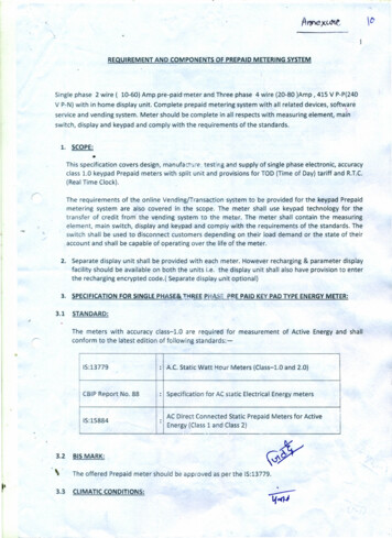
REQUIREMENT AND COMPONENTS OF PREPAID METERING SYSTEMSingle phase 2 wire ( 10-60) Amp pre-paid meter and. Three phase 4 wire (20-80 )Amp , 415 V P-P{240V P-N) with in home display unit. Completeprepaid meteringservice and vending system. Meter should be completesystem with all related devices, soft"'{,arein all respects with measuring element,switch, display and keypad and comply with the requirementsmainof the standards.1. SCOPE: This specification covers design, manufacture .testing and supply of single phase electronic, accuracyclass 1.0 keypad Prepaid meters with split unit and provisions for TOD (Time of Day) tariff and R.T.C.(Real Time Clock).r:The requirementsmeteringof the online Vending/Transactionsystem are also coveredsystem to be providedin the scope. The meterfor the keypad Prepaidshall use keypad technologyfor thetransfer of credit from the vending system to the meter. The meter shall contain the measuringelement, main switch, display and keypad and comply with the requirements of the standards. The-switch shall be used to disconnectcustomersaccount and shall be capable of operating2.3.1with each meter. However recharging & parameterencryptedcode.{ Separate display unit optional)SPECIFICATION FOR SINGLE PHASE& 'L EEPHA ·:.fF.tE PAID KEY PAD TYPE ENERGY METER:STANDARD:The metersconformwithto theaccuracyclass-1.0are requiredfor measurement15:13779: A.C. Static Watt Hour Meters (Class-1.0 and 2.0)CSIP Report No. 88: Specification15:15884:Energy and shallfor AC static Electrical Energy metersAC Direct Connected Static Prepaid Meters for ActiveEnergy (Class 1 and Class 2)BIS MARK:The offered3.3of Activelatest edition of following standards:-.3.2displayshould be available on both the units i.e. the display unit shall also have provision to enterthe recharging3.on their load demand or the state of theirover the life of the meter.Separate display unit shall be providedfacilitydependingPrepaid meter should be approved as per the 15:13779.CLIMATIC CONDITIONS:
The meter is required to operate satisfactorilydusty and tropical3.4conditionsi)Specified operatingii)Limit range of operationiii)Limit range of storage and Transportiv)RELATIVE HUMIDITY:rangewith specified accuracy under hot,specified as herein after:--10 C to 55 C-25 C to 55 C.-25 C to 70 C(a)Annual Mean 75 percent(b)For 30 days (spread over one year) 95 percent 85 percentv)(c)Occasionally on other daysMaximum attitude above M.5.1.vi)Average Annual rain fall1200 mm.1000 MeterCURRENT AND VOLTAGE RATING:Rated Voltage (Vref): 240 V Phase to NeutralRated Current (For Single Phase): Basic Current lOA (Ib)MaximumRated Current (For ThreePhase)current 60A (Imax): Basic Current 20A (Ib)Maximum3.5and continuouslyand other climatic conditioncurrent 80A (Imax)VARIATION IN POWER SUPPLY:The metersshall be suitablefor workingsatisfactorilywith the followingpowersupply systemvariations:3.5.iVOLTAGE RANGE:(i)Specified OperatingRange:0.7 to13. Vref(-30% to UENCY VARIATION:The standard reference frequency3.60.85 to 1.15 Vref i.e.-15% to 15%requirementfor performanceshall be 50Hz with tolerance. 5%.POWER CONSUMPTION:3.6.1 VOLTAGE CIRCUIT:r ,The active, apparentmeter at referencePower consumptionvoltage,referencelimits as specified in relevant IS.in voltage circuit including the power supply of thetemperatureand referencefrequencyshall be within
331 WHREN! ORt l·.The apparentreference3.7STARTINGPower taken by each currenttemperaturereferencefrequencyandCURRENT:The meter shall start registering3.8circuit at basic current,shall be within limits as specified in relevant IS.the energy at 0.2% of lb.ACCURACY:Class of accuracy of meter shall be 1.0 and shall conformto accuracy requirementas per specifiedIS. 3.9KEYPAD PREPAIDMETER:The keypad buttonsshall have numbers/letterson them, which shall be clearly visible and resistantto wear. The layoutof the numberingnumbers'1' through'9' and buttonssuch as "",physical identification(raised printingor a pip) to aid customers with poor sight .The keypad IP rating shall be adequatesafety of the user and preventingprovideaudiblefeedbackwhenshall be same as thatto permit'0', and '#'. Buttonchange shall be via encrypted.differingnumericrecognizedtones to distinguishassociatedbetweenwith programmingcodes. Code encryptionstandardtime delay of up to 20 seconds between subsequent/"'for'5' shall have some form ofingress of dirt and water to the unit. The keypad buttonspressed withcarried out using an internationally.telephonesuse with moist or wet hands whilst ensuring theinvalid entry. The entry of codes for credit or commandssuch as tariffused on standard/ decryptionshallvalid andfunctionsmust be(e.g. Triple DES). The meter shall permit akeystrokes.The meter has Keypad buttons which enables the user to view various displays available on themeter. The display parameters shall be as follows: Value of recent consumption The currentlyDays Left (based on consumptionactive rates, the prices charged for consumptionof units consumed of last seven days)at each rate, and the numberat each rate and the daily charges.Last 5 recharge codes entered in to the meter"AuthenticatedBilling Code (ABC)"#The total amount vendedShows the Refund code Displays monthly InstantaneousMaximumDate/Time,consumptionr.in Rupees / kWHDemand with occurrer.c \J\. of time and dateload and the projectedhourly cost of use at this loadS rial no.Voltage, current etc.Key code mode for punching code in to the meter# "AuthenticatedBilling Code":The meter shall display the 20 digit authenticatedcontain the followingfrozen value at midnightmeter reading code. The full 20 digit token shall(00:00 Hr) of month end- .lA (/
41. 5 digit cumulative2.kWh energy register.Date of frozen data.3. Credit balance, it may be positive or negative.4.The tamper flag, which only indicates whetherthere is any tamper or not.3.10 TARIFF:The meter should be programmablefor the tariff order in vogue entirely and will be updatedfrom time to time as per the tariff order, through vending code. The MIS report will be generatedby the Agency and submitted to the BHEL indicating list of consumers whose tariff has not beenchanged to new tariff.Followiagare the featuresrelated parameters3.10.1Minimumrequiredthroughcharges: Using the online vending system it shall be possible to define the minimumcharge for the applicableamounttariffcategory.less than the minimumdeduct the difference3.10.2in the meter for Tariff. It shall be possible to change the tariffvend code.of the minimumFixed Charges: MetersanctionedIf the consumerconsumeselectricityequivalentofcharge then at the end of the billing period the meter shallamount and the monthlyconsumptionshall be able to deduct fixed charges on dailyload based charges etc. The fixed charges shall be defined(Amount).basis such as meter rent,using the online vendingsystem.3.10.3 Tax/Duty:It shall be possible to define the tax percentagethroughon line vending system whichhas to be levied on the amount of the energy consumed.3.10.4Debt Management:It shall be possible to collect the debt from the consumerswith the use ofthe online vending system. The debt percentage shall be defined in the vending system .3.U COMMUNICATIONCAPABILITY:The meter shall be providedmeter throughwith an optical communicationport. It shall be possible to read thethe optical port with held hand device.3.12 GENERAL REQUIRMEENTSMeter shall be designed and constructedand under normal conditionsin such a way as to avoid introducingany danger in useso as to ensure specially the following:- Personnel safety against electric shock'.X·(v- Personnel safety against effects of excessive temperature.'" /Protectionagainst penetrationProtectionagainst spread of fire.3.12.1 All the materialand constructionof solid objects, dust and water,used in the manufacturingof meters shall be of highest quality. The entire designshall be capable of withstandingrough handling during transportation.stresses likely to occur in actual service and
53.12.2 All insulatingmaterialused in the constructionand of tested quality and shall conformnon ageingto tests as specified in relevant Standards.3.12.3 The meter shall be designed on applicationusing SMT (Surface Mount Technology)of meter shall be non-hygroscopic,specific integratedcircuit and shall be manufacturedcomponents.3.12.4 The terminal block, the terminal cover and the mete- case shall ensure reasonable safety againstthe spread of fire. They shou d not be ignited by thermic overload of live parts in contact withthem.3.12.5 The meter shall conformto the degree of protectionIP 51 against ingress of dust, moisture andvermin . 3.12.6 All parts whicheffectively.are subjectAny protectiveto corrosioncoatingunder normalworkingconditionsshall be protectedshall not be liable to change by ordinaryhandlingdue toexposure to air under normal working conditions.3.12.7 The metersshall be designedinterference,electrostaticsuch that their workingremainsdischarges and high voltage transientsunaffectedby electromagneticas specified in standard.3.13 CONSTRUCTIONAL REQUIREMENTS:3.13.1a.Meter Case:The metershall have completelyinsulatedbody and be of wall mountedmeter shall have a case made of unbreakablehigh grade fire resistant,projectedreinforcedtype. Thepolycarbonateor equivalent high grade engineering plastic which can be sealed in such a way that the internalparts of the meter are accessible only after breaking the meter cover seals. The meter cover shallhave at least two sealing screws, each screw having the sealing holes.b. The meter case shall have at least three mountingterminalc.block sealed beneath the terminalThe meter case shall be ultrasonically0 1 thedamaging the cover.LCD Unit:The display unit shall be Pin type built-inliquid crystal display. The measured value{s) shall bedisplayedon minimumsix digit Liquid Crystal display (LCD) i.e. display unit, having minimumcharactersize of Smm X 4mm. When the meter is not energized, the display need not be visible.Each display shall be retained for a minimumperiod of 2S. .3.13.3screwswelded with the meter cover in such a way that it shouldnot be possible to open the meter cover without3.13.2holes. Two holes for mountingcover and one for hanging screw on the top. Window:The metercover shall be of high grade, fire resistant,reinforcedpolycarbonateor equivalent,high grade engineeringplastic with one windowmade of UV stabilized,silicon coated,'polycarbonateor equivalent high grade engineering plastic for reading the register. The windowshall be integral part of the meter cover such that it can not be removedbreaking the meter cover,undamagedwithout)
r(63.13.4 Terminals and Terminals block:a.The terminalblock shall be made from best qualitypolycarbonateextensionor equivalenthigh grade engineeringof the meter case. If shall have terminalb. The meterpointed(not bakelite)shall be providednon-hygroscopic,with terminalof minimumto connectfire retardant,reinforcedplastic which should form aninternal diameter 8.5mmthe cables. The screws shall not haveedge at the end of thread. The clearance and creep age distance of terminaltips betweenthe terminaland the surroundingblock andparts of metal enclosure shall be as per relevantIS standard.c.All parts of each terminalother-metald.shall be such that the risk of corrosionresulting from contact with anypart is minimized.Electrical connectionsinsulating material.shall be so designedthat contactpressureis not transmittedthrough.3.13.5 Terminal Cover:a.The meter terminalBlock shall be providedsealing arrangementthe externalwith an extendedterminalin such a way that it shall cover the terminals,conductorsand their insulationcover with independentthe conductorfixing screws,i.e. no part of meter or cable accessories shall bevisible from the front of the meter.b.When the meter is mounted, no access to the terminalsseal of the meter terminal cover.shall be possible withoutbreaking the3.13.6 Terminal Arrangement:A diagram of connections.covershallconnections3.13.7be extendedshould be providedinside the cover the terminalblock. The terminalsuch that when it is placed in position it is not possible to approach theor connectingwires.Name Plate Marking:The name plate shall have followingmarkings which shall be indelible, distinct and readable fromoutside the meter:Manufacturer'sDesignationname and/or trade mark and the place (with country) of manufacture;of type;The no. of phases and no. of wires for which the meter is suitable for;The manufacturer'sserial number and year of manufacture;Reference voltage;The basic current and the maximumcurrent;The principal unit in which the meter reads;Meter constant;Class index of the meter;Reference Freq uency;3.14 TAMPER AND FRAUD PROTECTION:
I77The meter shall operate normally3.14.1Phase current3.14.2Neutral current3.14.3Phase and neutral interchange:3.14.4The meter3.14.5In ca conditions:reversal: The meter shall record forwardedenergy.reversal: The meter shall record forwardedshall operateconnectedunder the followingenergy.The meter shall record forwardednormallyenergy.in case the phase and neutralare swappedwithneutralto earth.the neutralis openedbypass the energywithearthshall be recordedload connected,on the wire whichpartialphase by pass or full phasehas highercurrentrecording.Suchtampers shall be logged in the memory of the meter.3.14.6 The meteringmagneticsystem shall be providedon the meteringMeasurementtamperingshieldingso that any externalneutral.The energy measurementand it is preferabledetect the measurementmemory.is disconnectedshall disconnectshall always be done on the elementwithshifting from phase to neutral circuit and neutral to phase circuit in thethe imbalancewith the pre defined thresholdIf neutralof energy as perto supply the CT's for both phase and neutral. The meter shallThis shall be done by findingcomparingand recordingby standard.shift: The meter shall have measuring element for both phase and neutral to avoidwithhigher current3.14.8magneticsystem shall not affect the proper functioningerror limits prescribed3.14.7with adequatefield (AC Electro Magnet or DC Magnet) as per the values specified in standard appliedbetweenphase and neutral currentandand the persistence time.from both supply & load side the meter shall not power up and / orthe supply.3.15.1 Type TestsMeter shall be fully type tested as per IS 13779/1999magneticinfluencethe constructional3.15.2tests as per CBIP l pass the entireup to date) and also additional3.15.3Prepaid functionality3.15.4Other Acceptancei)to prove that the meters meet the requirementsand routinetests as laid downacceptance tests as prescribedofin IS: 13779/1999in this specification.shall be tested by the BHEL as per IS: 15884/2010.testsThe meter shall withstand440 V betweenii)up to date) and external AC/DCof the type tested meters. All the Type Tests shall have been carriedout from any NABL accreditedthe specification.(amended(amended88. The Type Test Reports shall clearly indicatecontinuouslyphase and neutral withoutPower consumptionfor a period of at least 5 minutes at a voltage ofdamage/problems,tests, \,.
·'8iii)The meter shall withstand"iv)impulse voltage at 10kV.The meters shalt be tested at (-) 15% and at (-) 30% of referenceand ( ) 20% of referencerelevantv)voltage and shall record energy withinquantitieslike frequencyerror will be as per IS: 13779/1999as perto phase circuitin the memory.and neutralpersistencetime. conditionscurrentInterchangingNeutralin percentageshifting from phase to neutral circuit and neutralforwiththemeasurementand the meter shall log the forwarded1the limits of variationThis shall be done by findingand comparingThe condition23variation(amended up to date).The meter shall detect the measurementphaselimits of variationIS.For other influencevi)voltage as well as ( ) 10%the imbalancepre definedshiftthresholdshall be accordingbetweenand theto belowenergy in this conditions:of phase & neutral terminals.connectedon incomingside but connectedto earth viaresistor on outgoing side. Load is connectedsolidly to ground.Phase & neutraland load is connectedinterchangedat incomingto earth.4vii)Shorting is provided on current coil terminals.Meter shall record accurate energy in case of externalthe IS13779. Meternot operatemagneticshall be immunein this condition.inductionmagnetic influencingup to O.5T permanentIn case of abnormalmagnetic field such as continuousof 0.27 Tesla 5% and magnetic inductionshall perform the followingsignals as permagnet and the switch shallDCof 10 milli Tesla the meterfeatures:a) Meter shall log the event in its memory as Magnetic tamper with date and time stamp.b) Meter shall show "TAMPER" in the display.c) Meter shall start recording at 100% of Imax (Defrauded3.15.5metering)Demonstration of Meter:Two nos. Single Phase Prepaid meter with vending software and token generation system must beDemonstrated by bidder within 15 days of opening of Part-I. Below mention operation shall be done ondemonstration meters and bidders' representative shall be well equipped to demonstrate desired features:a} Vending system operation.b} Test of application of tariff.c}Token generation.d} Token punch & checking all display parameters on meter as well as parallel home display unite} . Balance available in the meter.
9Test of friendlyg)Test of disconnecth)Test of reconnecti)Test of disconnectj)Test of reconnectk)Test of visibleI audibleover load warning.I)Test of visibleI audiblelow credit warning.m).Authenticn)4.credit hours start & end timef)All tampersCONSUMERthe outputthe outputsupply once when credit reach to zero.supply on providingthe out supply if loadthe out supply if loadcreditI currentI currentlimitI chargingwith new token.exceed the preset value in the meter.falls below the preset value in the meter.Billing Code (ABC) verification.shall be tested as mentionedin the specification.INTERFACE UNIT (ClU): The meter shall be suppliedwith a separate The display unit shall be poweredIn-homedisplay unit ICIU.up from the meter The display unit shall have a LCD display. The displayavailableunit shall have a key pad to enter The displayunittelephonecable) . The In-home5.and energymeterdisplayunit IClUshallshouldIt shall be possiblebe connectedusing a 4 wireconnectioncable(Similartocable (Similartoshall be availableinalarm signal in case of low credit and overload.be providedwith5 meter4 wireconnectionI OR BCS:to read the prepaidmetersand minimumfollowinginformationreading data. The transaction All the events history with time based and category Tariff details including Monthly to the keypadcable).METER DATA READ THROUGH MRI ANDmeterbe similarport to connect to the meter. The display unit shall have a buzzer to generatetelephoneshouldon the meter. The display unit shall have an connection.the code. The keypadhistorydata with date and time.the TOD tables, slab tables and informationhistory and consumptionAll the accountrelatedfixed charges value.based information.informationdata of the energy consumedhke metercredit,about the currentfor last twelveemergencycreditactive rate price.months.details,minimumcharge and
10 6.All the limiting parameters shall also be available in meter reading.YENDING SYSTEM REQUIREMENTS:This section specifies the requirements of the vending system for currency based Prepaid metering solution.The meter shall work on the latest currency transfer keypad technology supported by an online vendingsystem. Since the keypad technology is future proof, cost effective and in this communication age, enablesconsumers to buy electricity over the multiple vending options.The vending system shall use Triple Data Encryption Standard (Triple DES),i.e. it provides three levels ofencryption for the vend code. The code shall be meter specific and can't be used in any other meter. TripleDESis widely used in banking systems worldwide due to the high level of security provided by the algorithm . The necessary licensed Software for each Vending Station at BHEL billing centre shall be provided bybidder.The vending system shall be the online vending system from where the vend codes shall be issued.7.VENDING PROCESS:7.1.1On receipt of the vend request. the system shall have a provision to ascertain the identity of theconsumer. The keys to identify the consumer shall be the meter serial number or consumer premisenumber.7.1.2The vend terminalshall send the request to a central database that shall authenticatethetransaction and generate an encrypted code.7.1.3In order to provide maximum security to the system the encryption shall not be done on the vendterminal.7.1.4On receipt of each request the vend terminal shall connect to the central database and get the codegenerated.7.1.5The code hence generated shall be printed on paper using the attached printer.7.1.6The vending system shall be used to transfer current values (Rupees) to the meter.7.1.7The consumer shall pay the money at the vend terminal, this information when fed to the vendterminalshall be send to the central database that shall encrypt the token using Triple DESencryptio'n algorithm.8.DATA MONITORINGCENTRE (DMe):The DMC shall be a part of the vending system which shall have capability to interface with the centraldatabase and produce the management reports as detailed in the specification. It shall manage alladministrative data, including settings of system accounts, tariffs, meter and Consumer data. It shall alsoprovide reporting system for system analysis.Various tasks that should be performed from the DMC are outlined below:8.1.1 Consumer Database Management\ Entry of new consumers and their details Existing consumer database
118.1.2Meter Database Management 8.1.38.1.4Uploading of meter databaseTariff Management Tariff structure definition Rate Price definition Tariff category Tax percentage Fixed Charge value Minimum charge value Slab reset period Tariff change administrationLimit Parameters management Define Load Limit Current Limit value Emergency CreditDebt (previous charges) Management8.1.5 Transaction management:. 8.1.68.1.7 Cash vend transaction Retained credit transaction Refund Money Transaction Previous Charge TransactionReports Debt collection and outstanding report Tax and duties accounts report Customer's Vend ReportImport of data by the vending station from the master station / Export of data by the main stationto the vending stations:8.1.8 Import of data from Comma separated valuf's(CSV) format files Export of data in CSVformat.User Security Management
.129. Group rights definition Entry of system users and allocation of group rightsSECURITYASPECT:The vending system shall be a sophisticated SYSIemwith reliable security features.a) The token created for particular meter with the defined tariff shall not be used for any other meter.b) The meter shall accept the valid token only once. The token generated shall be meter specific and shallbe used only on the particular meter for which it is intended.c) The to.J enshall not be reusabled) The token shall be re-issued in case it is lost the meter shall accept the code generated only once.e) Whenever a tariff change takes place no other token shall be accepted by the meter unless the updatedtariff token is entered into the meter.f)The token generated shall be authenticated as well as encrypted so that no decoding is possible.;,. The complete system and meter shall be guaranteed/warrantyfor 5 year from date of receipt ofmaterial at BHEl store. Vending server transaction charges for energy meter for no. coupons per Meter annually for 5 Yearsshould be included in offer .,. Bidder/firm should visit site for actual requirement /condition before quoting in aforesaid Tender. &it.- 1"lzrr L ]A{"pl 7. l1 3Y y tf 3 -1)I ])--['fJ'PJe
The meters with accuracy class-1.0 are required for measurement of Active Energy and shall conform to the latest edition of following standards:-15:13779 : A.C. Static Watt Hour Meters (Class-1.0 and 2.0) CSIP Report No. 88 : Specification for AC static Electrical Energy meters 15:15884 : AC Direct Connected Static Prepaid Meters for Active