Transcription
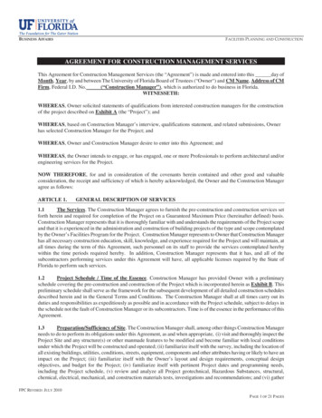
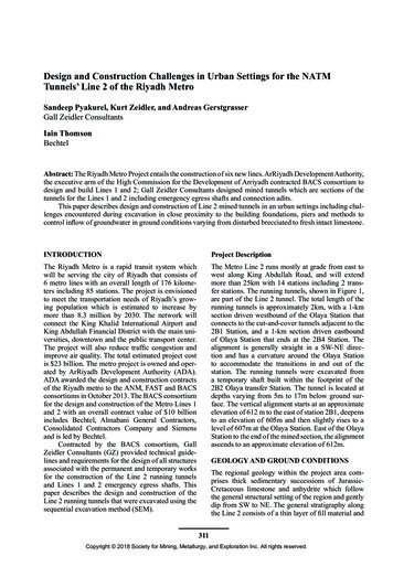
Design and Construction Challenges in Urban Settings for the NATMTunnels’ Line 2 of the Riyadh MetroSandeep Pyakurel, Kurt Zeidler, and Andreas GerstgrasserGall Zeidler ConsultantsIain ThomsonBechtelAbstract: The Riyadh Metro Project entails the construction of six new lines. ArRiyadh Development Authority,the executive arm of the High Commission for the Development of Arriyadh contracted BACS consortium todesign and build Lines 1 and 2; Gall Zeidler Consultants designed mined tunnels which are sections of thetunnels for the Lines 1 and 2 including emergency egress shafts and connection adits.This paper describes design and construction of Line 2 mined tunnels in an urban settings including challenges encountered during excavation in close proximity to the building foundations, piers and methods tocontrol inflow of groundwater in ground conditions varying from disturbed brecciated to fresh intact limestone.INTRODUCTIONProject DescriptionThe Riyadh Metro is a rapid transit system whichwill be serving the city of Riyadh that consists of6 metro lines with an overall length of 176 kilometers including 85 stations. The project is envisionedto meet the transportation needs of Riyadh’s growing population which is estimated to increase bymore than 8.3 million by 2030. The network willconnect the King Khalid International Airport andKing Abdullah Financial District with the main universities, downtown and the public transport center.The project will also reduce traffic congestion andimprove air quality. The total estimated project costis 23 billion. The metro project is owned and operated by ArRiyadh Development Authority (ADA).ADA awarded the design and construction contractsof the Riyadh metro to the ANM, FAST and BACSconsortiums in October 2013. The BACS consortiumfor the design and construction of the Metro Lines 1and 2 with an overall contract value of 10 billionincludes Bechtel, Almabani General Contractors,Consolidated Contractors Company and Siemensand is led by Bechtel.Contracted by the BACS consortium, GallZeidler Consultants (GZ) provided technical guidelines and requirements for the design of all structuresassociated with the permanent and temporary worksfor the construction of the Line 2 running tunnelsand Lines 1 and 2 emergency egress shafts. Thispaper describes the design and construction of theLine 2 running tunnels that were excavated using thesequential excavation method (SEM).The Metro Line 2 runs mostly at grade from east towest along King Abdullah Road, and will extendmore than 25km with 14 stations including 2 transfer stations. The running tunnels, shown in Figure 1,are part of the Line 2 tunnel. The total length of therunning tunnels is approximately 2km, with a 1-kmsection driven westbound of the Olaya Station thatconnects to the cut-and-cover tunnels adjacent to the2B1 Station, and a 1-km section driven eastboundof Olaya Station that ends at the 2B4 Station. Thealignment is generally straight in a SW-NE direction and has a curvature around the Olaya Stationto accommodate the transitions in and out of thestation. The running tunnels were excavated froma temporary shaft built within the footprint of the2B2 Olaya transfer Station. The tunnel is located atdepths varying from 5m to 17m below ground surface. The vertical alignment starts at an approximateelevation of 612 m to the east of station 2B1, deepensto an elevation of 605m and then slightly rises to alevel of 607m at the Olaya Station. East of the OlayaStation to the end of the mined section, the alignmentascends to an approximate elevation of 612m.GEOLOGY AND GROUND CONDITIONSThe regional geology within the project area comprises thick sedimentary successions of JurassicCretaceous limestone and anhydrite which followthe general structural setting of the region and gentlydip from SW to NE. The general stratigraphy alongthe Line 2 consists of a thin layer of fill material and311Copyright 2018 Society for Mining, Metallurgy, and Exploration Inc. All rights reserved.
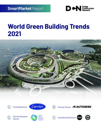
North American Tunneling: 2018 Proceedingsand silty clay with limestone fragments and cementedgranular materials overlie the Arab Formation. TheArab Formation is a contorted and brecciated alternation of limestone and thin beds of anhydrite consisting of four stacked carbonate-evaporite cycles,named Upper Limestone Breccia, Arab-C DisturbedBedded Limestone, Lower Limestone Breccia andArab-D Undisturbed Bedded Limestone. The minedtunnel plan and profile view with geology is shownin Figure 2.The Upper Limestone Breccia member represents cemented breccia of collapsed blocks of theoverlying Sulaiy formation mixed with limestoneblocks from Arab formation. This member originates from the dissolution of the Hith Anhydritemember initially present between the Sulaiy andArab Formations. The breccia is generally matrixsupported and comprises clasts ranging from coarseQuaternary alluvial deposits comprising interbedded layers of silty sand and gravel overlying anhydrite and limestone rock members of Cretaceousand Jurassic age. Three different rock formationsnamely the Sulaiy Formation, Arab Formation andJubaila Formation are encountered from top to bottom respectively. The Cretacious Sulaiy Formationconsists predominantly of limestone with calcarenitebeds and outcrops along East Riyadh. The JurassicArab Formation comprises limestone and brecciatedlimestone. The Jurassic Jubaila Formation compriseslimestone with some calcrenite beds and mostly outcrops along West Riyadh.The running tunnel alignment cuts throughthe carbonate members of the Arab Formation andencroaches locally into the Sulaiy Formation at theeast close to Station 2B4. Thin layers of fill andQuaternary deposits comprising mostly silty sandFigure 1. Line 2 Tunnel alignment (red) Running Tunnel and its proximityto the other structuresFigure 2. Mined tunnel plan and profile view with geology312Copyright 2018 Society for Mining, Metallurgy, and Exploration Inc. All rights reserved.
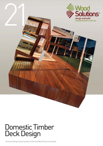
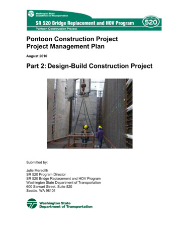
Sequential Excavation MethodsAustrian Tunneling Method (NATM). The excavation and support method was selected to preservethe load-bearing capacity of the surrounding rockmass which mobilizes the strength of the groundand allows implementation of lighter support. Theselected excavation and support method also considered the timing of the support installation to optimizesupport requirements. The design also provided toolbox item such as rebar spiles as local measure to provide additional support when soft, highly fracturedrock or soil was encountered in the crown.The primary lining comprised 250mm of steelfiber-reinforced shotcrete lining and systematic rockdowels. The rock dowels were designed with a lengthof 3m spaced in a 2m 1.5m staggered pattern. Thedashed line on Figure 3 indicate those rock dowelswithin which were omitted during construction dueto the prevailing good ground conditions. The excavation and support sequence typically included a1.5m long top heading round followed by installationof rock dowels and shotcrete lining. During construction, the 1.5m round length was gradually increasedto a maximum of 3m upon encountering of groundwith relatively good rock mass quality. The cyclewas repeated twice followed by staggered excavation and support of bench/invert with a round lengthof 3m. The secondary lining comprised 300mm ofcast-in-place steel fiber-reinforced concrete. A fullround waterproofing membrane was placed betweenthe primary and secondary linings to prevent waterinflow into the tunnel.The running tunnels were also connected to thetwo Emergency Egress Shafts by means of smallerconnecting adit tunnels. The adits were constructedusing SEM by breaking out from the Line 2 SEMrunning tunnels. The tunnel design was in accordance with BS EN 1990, BS EN 1991, BS EN 1992,and BS EN 1997. Structural loading predicted inthe numerical models was in accordance with BSEN 1997, Design Approach 2. The primary liningwas assumed to degrade over the design life, andwas designed to provide temporary support prior toinstallation of the secondary lining.The sprayed primary lining concrete mixwas designed to a compressive strength of classC20/25 and early age strength gain per J1 curve. Aperformance-based requirement was followed for thesteel fibers which were specified to provide a strengthof class D3/S2 as defined by BS EN 14487‑1:2005. The secondary lining mix was specified tohave a compressive strength of C30/37 class alongwith residual flexural strength of 2Mpa at mid-spandeflection corresponding to a crack mouth opening displacement (CMOD) of 3.5mm. The forcesimposed on the lining were determined using a 2Dand 3D finite element model (Figure 4). The threedimensional finite element analyses were performedgravel to very large sized boulders. The Arab-Cmember comprises very thin to thinly bedded calcareous claystones, calcareous siltstones and reddishbrown partially dolomitised calcarenite and finegrained siliceous limestone. This member is similar to the one encountered in the Upper LimestoneBreccia originating from the dissolution of brecciabeds. The Lower Limestone Breccia comprises moderately weathered, moderately to well-cemented,moderately strong, creamy white to yellowishbrown, matrix-supported clasts of limestone breccia.Some larger clasts have been dolomitised and arestrong to very strong. The matrix comprises yellowish brown, mottled white silt, some clay, and minorquantity of fine sand. The Arab-D member comprisesgrey to bluish limestone and some calcarenite beds.The limestone is slightly weathered, thick to verythin sub-horizontally bedded and undisturbed.The west tunnel is mostly within the DisturbedBedded Limestone with tunnel roof reaching theUpper Limestone Breccia at higher elevations. Theeast tunnel is mostly within the Upper LimestoneBreccia while the invert reaches the lower DisturbedBedded Limestone near the Olaya Station. Both ofthese members are highly heterogeneous and displayvarying behavior based on the intactness of the rock.Weathered profiles characterize the shallow strataespecially at the eastern part of the alignment, however localized seams of deteriorated material wereexpected along deeper level. Sub-horizontal andsub-vertical discontinuities and vugs characterizethe entire Arab-C Formation and local failures wereexpected during excavation.Dissolution cavities were expected in all limestone formations. These cavities originated from dissolution of limestone and anhydrite beds by acidicgroundwater along fractures and discontinuities,which is a typical karstification process in carbonaterocks. The upper members of the Arab formation aremost prone to such cavities.The carbonate rocks encountered along thealignment of the Line 2 mined tunnels comprisethe main regional aquifer in the Riyadh area. Thegroundwater level is highly variable in the city ofRiyadh as it is influenced by infiltration from sewageand is hydraulically connected to the shallower aquifers developed in the gravel in surrounding areas.Therefore, groundwater levels displayed a significant seasonal variation along with very high permeability of the limestone formation led to significantgroundwater inflow in the tunnel.TUNNEL DESIGN AND ANALYSISThe cross section has maximum height of 9m andwidth of 10.9m at the tunnel springline (Figure 3).The excavation and support design followed theprinciples of SEM which is also referred to as New313Copyright 2018 Society for Mining, Metallurgy, and Exploration Inc. All rights reserved.
North American Tunneling: 2018 ProceedingsFigure 3. Typical tunnel geometry: (a) primary lining, (b) typical excavated sequence with rock dowels,and (c) secondary liningThe tunnel lining was designed for fire exposure in accordance with the Riyadh Metro projectrequirements. The concrete mix was designed for a3 hours of minimum fire resistance (Figure 5). Thefire design curve ISO-834-1 with temperature curvedextended to a minimum of 180 minutes was considered in the design. The ISO 834-1 for 180 minutes(HC and RWS curves are commonly used for roadtunnels due to the higher fire HRR). For improvedfire resistance of the secondary lining a microfilament Polypropylene (PPE) fibers were added to theconcrete mix. Fire tests were conducted to determinePPE fiber dosage and the test results indicated that aminimum of 1kg/m3 of the PPE fibers is sufficient toachieve the required fire resistance. Further, the PPEfibers were only added to the secondary lining mixfor the arch portion of the tunnel and no PPE fiberswere added for the invert mix since there was a second stage concrete to cover the entire invert.with the software Rocscience Phase 2 for 2D analysis and Midas GTS NX for 3D analysis. Groundelements were modelled with 4-noded tetrahedralelements. Sprayed concrete lining elements weresimulated with two-dimensional three-noded plateelements, and rock dowels were modelled with onedimensional embedded truss elements.Green (fresh) sprayed concrete is subjected tocreep during installation due to deformations causedby ground loadings. Based on experience, a stiffnessof 7.5GPa was used for green shotcrete to account forcreep during installation of the first layers of sprayedconcrete. A stiffness 15GPa was used to model thestiffness of the hardened sprayed concrete for theprimary lining. The designed ground parameters areshown in Table 1.A waterproofing system was required to providelong-term protection of the running tunnels againstmoisture and water inflow. In order to ensure durability of the tunnels, the design specified installationof fully tanked sheet PVC waterproofing membranebetween the primary and secondary linings to actas a permanent water barrier all around the minedsection.Ground MovementDuring design development, calculations were performed to estimate the surface settlements inducedby the tunnel excavation. Representative cross314Copyright 2018 Society for Mining, Metallurgy, and Exploration Inc. All rights reserved.
Sequential Excavation MethodsFigure 4. 3D Finite element model for the mined tunnel with connecting Adits: (a) model constructionstages, (b) stage after support installation, and (c) axial forces developed in the rock dowelsTable 1. Ground parameters used in the designStrataFill/SoilArab Formation—Upper LimestoneBreccia (Highly Weathered)Arab Formation—Upper LimestoneBreccia (Moderate Weathered to Fresh)Arab Formation (Arab C)—DisturbedBedded LimestoneArab Formation—LowerLimestone BrecciaYoung’sUnitModulus oefficient ofLateral EarthPressureat 2570000.30492200.52tunnel convergence monitoring cross-sections at predetermined tunnel sections and surface settlementmonitoring points. Each in-tunnel monitoring section consisted of 5 convergence monitoring points(3D optical targets) around the tunnel periphery,while surface settlement monitoring was carried outusing automated total stations and optical targetsarranged along the alignment.sections in both 2D and 3D models were developedtaking into account construction sequence, geology,and proximity to existing structures, tunnel geometry, and the construction of break-outs. Based onthe results, settlement contour lines were derivedalong the entire Line 2 alignment. The maximumsurface settlement above the tunnel centerline waspredicted to be slightly over 2mm with virtually noadverse impacts on buildings and infrastructure during construction of the running tunnels. To measureground movement around the tunnel opening duringexcavation, the design required installation of in-CONSTRUCTIONThe Line 2 running tunnels were constructed following the SEM principles. Two Alpine roadheaders315Copyright 2018 Society for Mining, Metallurgy, and Exploration Inc. All rights reserved.
North American Tunneling: 2018 Proceedingsimplemented after excavation and full support of10-15 rounds of top heading. Systematic probingwas performed to allow investigation of deterioratedground and/or groundwater ahead of the advancingtunnel face. Typical probing comprised 17-meterlong probe holes with minimum overlapping of 5m.The tunnel geometry was locally enlarged when soft,highly fractured rock or soil was encountered in thetunnel crown to facilitate installation of the groutedsteel pipes to provide additional support and minimize ground instability.Throughout the project, two Senior SEMEngineers were available at all times on site to ensurethat the design was adhered to throughout the construction process. This was achieved by leading thedaily Shift Review Group meeting (SRG) and preparing the Required Excavation Support Sheet (RESS)in agreement with the tunnel construction teamwhich was represented by the BACS Constructionwere used for the excavation (Figure 6). The tunnel excavation commenced from temporary shaftslocated within the footprint of the Olaya station (eastand west sides), which was still to be built. The running tunnel excavated westbound transitioned to anopen-cut excavation while the eastbound tunnel transitioned into the 2B4 Station.The tunnel construction started in November2014 and was completed in December 2015.Excavation and support was a 24-hour operationof two 12-hour shifts for 6 days per week. Duringconstruction, the excavation sequence was adjusteddepending on the ground conditions. In betterground, the top heading round length was increasedto a maximum of 3m. Similarly, the timing andround length of bench/invert excavation was modified accordingly since no immediate ring closure wasrequired in good competent rock. The bench/invertexcavation and support installation was usuallyFigure 5. Standard ISO 834 temperature-time curve for a 3-hour firedurationFigure 6. Tunnel excavation with roadheader (left) and secondary lining formwork (right)316Copyright 2018 Society for Mining, Metallurgy, and Exploration Inc. All rights reserved.
Sequential Excavation MethodsTunneling in such setting of minimal cover wasvery challenging and required a careful and wellthought out design. Mined tunnel construction underthe open cut area was made possible by the installation of a temporary, roof-shaped slab (‘turtle back’)alorng the open cut section above the tunnel roof.The existing backfill material was used as earthform. A plastic sheet on top of the fill material wasused as separation layer. The ‘turtle back’ was nominally reinforced with wire mesh. The concrete roofslab was finally cast with the finished structure forming an arched-type lid above the tunnel section. Themined tunnel was excavated under this canopy in3-meter top heading rounds. Shotcrete primary liningwas placed against all exposed rock surfaces in thesidewalls. The two ends of the concrete canopy lid atthe interface with the existing rock were reinforcedwith spiles to avoid overbreak at the interfaces, prevent movement and maintain tunnel profile. Figure 8illustrates a section of the concrete canopy lid during construction. In the same area, Figures 8c and8d also illustrates the close proximity of the tunnelcrown with respect to the foundations of residentialbuildings and close proximity to the above groundbridge viaduct highlights the tunneling complexity insuch urban settings.Figure 7. Running tunnel (dashed red line) andits proximity to above ground buildings andviaductManager, Head Geologist, Head Surveyor, Healthand Safety Officer and Quality Manager. Adaptationsto cater for geological and hydrological conditionsas well as to construction and logistic requirementswere made in agreement between all SRG membersduring the daily meetings. During the daily meetings, monitoring data, observations and any unexpected occurrence as well as specific issues such asquality of workmanship were reviewed and adaptations or corrective measures agreed upon. No tunnelexcavation was permitted without a RESS being ineffect and signed by all involved.Challenging GeologyOne of the anticipated primary challenges duringconstruction was the presence of fractures and dissolution features within the limestone. The aquiferstypically developed in carbonate rocks have highpermeability due to increased secondary porosityassociated with karstic or other dissolution featuressuch as vugs. These vugs were observed in boreholecores recovered during the geotechnical exploration program. These dissolution features developedalong the sub-horizontal and sub-vertical joints anddiscontinuities, encountered in the Arab Formation.Therefore, the presence of undetected voids and cavities presented significant construction risk. Very thininterbeds of dark brown very weak laminated marlswere also identified which represented weak seamswithin the rock. The fractured and less cemented layers within the limestone and breccia were also proneto develop rock slabs for fall out. In general, though,the actual ground conditions encountered duringexcavation were mostly favorable with competentrock except for few instances, mostly along the westalignment, where cavities and rock slabs were notedwithin the disturbed bedded limestone.As part of the risk mitigation, systematic probing was performed from within the tunnel to identify geology ahead of the advancing tunnel face. Theprobing provided information regarding the presenceof weak or fractured rock as well as the presenceof any cavities or voids. In case that such adverseChallenging Urban SettingsThe tunnel passed under building foundations andunderneath the viaduct pier and therefore it wascrucial to minimize ground movement during excavation to avoid impact to the overlying structures.Figures 1 and 7 also illustrates the critical structuresalong the tunnel alignment. The round length of thetunnel heading advance was reduced at these locations. Similarly, attention was given during construction for any possible future construction andtunnel support design was modified accordingly tomake such future construction easier. For instance,GRP rock dowels were used in lieu of steel dowelsat locations of future breakouts and at the end of thetunnels at 2B4 stations where new structures had tobe constructed directly above the tunnel.No discernible settlement or ground movementwas observed and none of the above ground structures was impacted during construction.A section of the west tunnel passed below anexisting open cut excavation with the tunnel crowndaylighting into the open cut. This open cut hadbeen excavated prior to the tunnel construction, for alarge commercial building foundation and was laterbackfilled.317Copyright 2018 Society for Mining, Metallurgy, and Exploration Inc. All rights reserved.
North American Tunneling: 2018 ProceedingsFigure 8. Construction of west tunnel section within the open cut area: (a) tunnel configuration withrespect to backfill and canopy lid, (b) open cut area before tunnel excavation, (c) backfill with PVCabove the tunnel section, and (d) tunnel concrete canopylength of the tunnel, but significantly above crownlevel along most part of the westbound tunnel andat invert level or below along the eastbound tunneland therefore significant groundwater inflows wereexpected during excavation at locations of the westbound tunnel. Furthermore, probe holes were converted into dewatering holes when required to allowgravity drainage. The groundwater discharge ratethrough the probe holes was noted. It was plannedinstall drain holes around the excavation periphery,if pre-determined values were exceeded, to injectgrout and control the groundwater inflow. Suchmeasures were not required to be implemented during the construction. Drain mats and flexible drainhoses encased in shotcrete were used to collect localized water inflow and allow shotcrete installationwhile channeling the water into small temporarysumps located near the invert. As the tunnel excavation progressed, a trench was excavated alongthe invert centerline and a 12-inch perforated pipewas installed along the trench to divert all collectedgroundwater along the tunnel to a temporary pumpsump (Figure 9). The temporary sump was locatedground conditions were anticipated, mitigation measures such as reduction in round length and filling ofthe voids were adopted along with other local support measures (tool box items such as spiling) prescribed by the design. Rebar spiles were particularlyrequired to be installed at the break-in and break-outlocations and under shallow cover close to the tunnel portals to provide additional support, limit overbreak and minimize ground settlement. Overall, thecarefully designed robust systematic support systemallowed completion of the tunnel excavation andsupport on schedule avoiding delays despite thechallenging ground conditions at due to dissolutionfeatures and fractured rock.Groundwater ManagementGroundwater control was an additional challengeduring construction. The presence of dissolutionfeatures and pores increases the permeability in bedded limestone and breccia and provides preferredgroundwater flow path which increases groundwaterinflow. The groundwater level was varying over the318Copyright 2018 Society for Mining, Metallurgy, and Exploration Inc. All rights reserved.
Sequential Excavation MethodsFigure 9. In-tunnel groundwater control: (a) trench with inlet and outlet piles, (b) temporary sumpFigure 10. Front view of the temporary sump: before and after completion of final liningin the middle of the west tunnel at its lowest pointand contained three 6-inch dewatering pumps. In anurban environment, discharge of groundwater posesan additional challenge on the construction team.The invert-trench between the temporary sumpand the open excavation for the Olaya Station alsoaccommodated two solid 8' pipes, which were usedfor groundwater discharge back into a pump sump atOlaya Station. From there the water was pumped tothe surface and discharged. The pumps were in continuous operation until completion of the final liningdue to the high groundwater recharge rate.The high inflows resulted in increased potentialfor flooding of the tunnels in case of failure of thedewatering pumps and pumping redundancy was inplace to mitigate the risk. At one instance, groundwater discharge of as much as 1500cm3/min hadto be pumped from the west tunnel to provide safeworking conditions. The east tunnel was relativelydry, not requiring major groundwater managementmeasures.Closure of the sump for installation of the invertfinal lining was a significant construction challengeas the pump had to be in operation at all times. Atemporary closure of the pump could easily flood thetunnel due to the large water inflows and would causeinvert heave in the tunnel section where the arch wasnot completed. Therefore, a carefully designed planwas executed to finally close the temporary sumppit and complete the secondary lining installation.Before closing of the sump pit, the secondary liningincluding the invert was completed along the tunnelalignment. For the closure of the sump pit, at first,the feeding pipes into the sump pit were cut flush tothe sump walls to provide a flat substrate for installation of PVC membrane and then ground anchorsalong with blinding and gravel layer were installedon the base of the sump. A PVC membrane alongwith drainage mats were installed over the sumpfaces. A perforated T-shaped drainage pipe was theninstalled to keep the dewatering system running andprevent build-up of groundwater pressure duringconcrete curing.319Copyright 2018 Society for Mining, Metallurgy, and Exploration Inc. All rights reserved.
North American Tunneling: 2018 Proceedingsprobing and presence of experienced on-site SEMpersonnel were key for the successful execution ofthe project. The presence of dissolution features,including cavities, groundwater, and fractured rockpresented significant construction challenges whichwere addressed with consideration of the geologyand careful interpretation of ground probing ahead ofthe tunnel face. Identification of adverse ground conditions ahead of the tunnel face including the presence of groundwater allowed mitigation of such risksby either reducing the round length or implementing grouting program. Although the running tunnelswere excavated in an urban setting in close proximityto building foundations and viaduct piers, no adverseimpact to the existing structures was observed as aresult of a carefully designed and executed tunnelexcavation and support. Adherence to the design wasensured by experienced SEM Engineers through thedaily SRG meeting where the excavation and support requirements were discussed and agreed forimplementation.A 4-inch drainage layer comprising of cleancrushed stone was placed above the sump pit toallow the filtered water reach into the perforatedT-pipe. A PVC membrane was installed on top of thedrainage layer and connected to the PVC membraneof the sump walls. The sump pit was then filled withconcrete under continued pumping to avoid groundwater pressure building during curing. Additionalrelief pipes were attached to the top of the finishedconcrete extending all the way to the top surface ofthe finished invert secondary lining (Figure 10). Ifwater discharge was observed through the pressurerelief tubes, a pumping was implemented to reducethe water pressure and ensure depressurized conditions for the invert pour above the sump.CONCLUSIONThe Line 2 running tunnels were successfully constructed without any delays or impact to the utilitiesand structures located above the tunnel alignment.A systematic and robust design along with ground320Copyright 2018 Society for Mining, Metallurgy, and Exploration Inc. All rights reserved.
round waterproofing membrane was placed between the primary and secondary linings to prevent water inflow into the tunnel. The running tunnels were also connected to the two Emergency Egress Shafts by means of smaller connecting adit tunnels. The adits were constructed using SEM by breaking out from the Line 2 SEM running tunnels.