Transcription
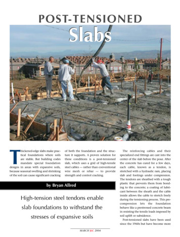
POST-TENSIONEDSlabsThickened-edge slabs make practical foundations where soilsare stable. But building codesmandate special foundationdesigns in areas with expansive soils,because seasonal swelling and shrinkingof the soil can cause significant crackingof both the foundation and the structure it supports. A proven solution forthese conditions is a post-tensionedslab, which uses a grid of high-tensilesteel cables — rather than conventionalwire mesh or rebar — to providestrength and control cracking.by Bryan AllredHigh-tension steel tendons enableslab foundations to withstand thestresses of expansive soilsMARCH JLC 2004The reinforcing cables and theirspecialized end fittings are cast into thecenter of the slab before the pour. Afterthe concrete has cured for a few days,each cable, known as a tendon, isstretched with a hydraulic ram, placingslab and footings under compression.The tendons are sheathed with a toughplastic that prevents them from bonding to the concrete; a coating of lubricant between the sheath and the cableinside allows the cable to stretch freelyduring the tensioning process. This precompression lets the foundationbehave like a prestressed concrete beamin resisting the tensile loads imposed bysoil uplift or subsidence.Post-tensioned slabs have been usedsince the 1960s but have become more
common over the past two decades. Asa structural engineer with a Californiafirm that designs hundreds of posttensioned residential slabs each year,I’ve found that they’re simple to build,economical, and reliable.Soil ConditionsSlab Movement on Expansive SoilsEdge DryingPerimeterloadUniform oisturevariationdistance(em)Slab edgesdistort downwardduring dry weatherSlab lengthEdge SwellPerimeterloadPerimeterloadUniform loadYmemSlab edgesdistort upwardduring wet weatherFigure 1. The “Ym” value of a soil can be thought of as a measure of itspotential for expansion: the higher the value, the greater the soil movement as conditions swing from wet to dry and back again. The “em” value,which describes the distance inward from the slab edge that the soil moisture can be expected to vary, is mostly a function of the local climate.MARCH JLC 2004California and Texas are well knownfor their expansive clay soils, but similarsoil conditions are found across a wideswath of the central Great Plains and inpockets of varying size nationwide.Expansive soils are an especially serious problem in areas with wideseasonal variations in soil moisturecontent. During hot, dry summerweather, clay soils shrink, whileextended periods of wetter weathercause the soil to expand. Since the slabitself tends to protect the soil directlybeneath from wetting and drying, mostswelling and shrinking take place at theedges (see Figure 1). Determining theexpansiveness of a given soil is a job fora qualified geotechnical engineer.Measuring soil expansiveness. Indesigning a foundation, two variablescovered in the soils report are especiallyrelevant to the structural engineer. Thefirst is the Ym value, or DifferentialSwell, which refers to the extreme rangeof soil movement that could occur.(Like other worst-case engineeringvalues, this number expresses a possibility and doesn’t mean that that muchmovement will occur.) Differential Swellis expressed in inches. A value of 4 orless indicates that the soil can support aproperly designed post-tensioned slab.If the Ym figure is higher than 4,a geotechnical engineer will need todevelop a different — and generallymore costly — foundation plan. Onecommon approach would be tobore down to bedrock or competentsoil and cast piers that support agrade-beam foundation (see “TroubleFree Foundations for Expansive Soils,”11/02).Moisture penetration. The secondkey value is what’s known as the EdgeMoisture Variation Distance, or em.This refers to the distance inward from
the edge of the slab that the soil moisture content can be expected to vary.As you would expect, this number islargely a function of local climate: Thewetter the conditions, the farthermoisture can be expected to penetrate;the drier the conditions, the wider thearea of drying. The higher the emvalue, the greater the stresses actingon the slab. A good source for moreinformation is Design and Constructionof Post-Tensioned Slabs-on-Ground(Post-Tensioning Institute, Phoenix,Ariz.; 602/870-7540, www.post-tensioning.org).Uniform-Thicknessvs. Ribbed SlabsThere are two basic types of posttensioned residential slabs. Uniformthickness slabs are typically about 9inches thick throughout, except at theperimeter footings and where isolatedfootings are needed to accept heavypoint loads or provide extra embedment depth for metal structuralconnectors.Ribbed slabs, by contrast, usuallymeasure about 5 inches thick butcontain an internal grid of thickerfootings that give them a waffleshaped cross section. These ribs can beplaced up to 17 feet apart in eachdirection and are required to extendfrom one slab edge to the other.They’re typically located under wallsor posts, so their placement is tied toarchitectural drawings. In addition toproviding strength and stiffnessagainst expansive soil movement, theribs can be used to anchor metalconnectors and shear walls.Slab loading. Although heavy structural loads are usually carried by footings, post-tensioned slabs are strongenough to carry moderate loadsdirectly. When planning for pointloads, a safe rule of thumb is to figureon 1,000 pounds per inch of slab thickness. A 5-inch post-tensioned slab canhandle up to 5,000 pounds, and a typical 9-inch-thick slab will bear a concentrated 9,000-pound load. In addition,both the International Building Code andthe Uniform Building Code providedesign methods for determining thecapacity of a post-tensioned slab tosupport the load from a bearing wall.Especially with a uniform-thicknessslab, this may make it possible to doaway with interior footings entirely.Labor and materials. Uniformthickness slabs have the advantage ofsimplicity. Most of the trenching islimited to the exterior footings, whichhelps keep labor costs down. On theother hand, uniform-thickness slabsrequire more concrete. Plus, becausethe minimum number of tendons forthe slab is determined by its crosssectional area, the uniform-thicknessslab will also require more tendonsthan a thinner ribbed slab of the samesquare footage.In practice, either approach can beused to satisfy the strength and stiffnesscriteria of the code. We find that mostbuilders simply go with the versionthey’re most familiar with.Excavation and FormsExcept for the reinforcing, posttensioned slabs are excavated andformed exactly like conventional residential slabs. Once the site has beencleared of vegetation and other organicmaterial, the slab is laid out andstaked, along with the positions of anyinternal ribs. The clay soils we workwith are generally solid and hard, sovertical-walled trenches readily holdtheir shape (Figure 2, previous page).In looser soils, trenches must sometimes be sloped to prevent loose material from falling into the bottom.There’s a minimal danger of upliftfrom frost in our part of California, sothe perimeter footing only needs to bedeep enough to satisfy the soils reportand to resist the vertical, lateral, andexpansive soil load of the structure. Ourcompany uses a minimum 18-inchembedment into the soil at the exteriorfootings. The trenches that form theribs are also about 18 inches deep.Figure 2. A worker usesa rotary hammer toexcavate hard clay thatforms the subgrade of aribbed slab. The networkof intersecting trenchesdefines the internal footings, or ribs, that willstiffen the slab and helpit resist soil movement.MARCH JLC 2004
Once the foundation crew has stakedthe perimeter forms in place and bracedthem with diagonal kickers, they coverthe prepared subgrade with a polyvapor barrier. With a uniform-thicknessslab, it’s easy to do this with a fewcontinuously overlapping sheets. Aribbed slab, with its internal trenches, isa little trickier. The usual constructionpractice is to cover each soil “block”with its own sheet of poly and leave thetrenched areas uncovered (Figure 3).The poly is typically covered with alayer of sand or gravel, as specified bythe geotechnical engineer, to protectthe vapor barrier from damage whenthe concrete is placed and to help withthe curing of the concrete.Figure 3. A poly vapor barrier on each soil “block” is held in place with a layer of sand.Where plumbing or conduit runs beneath the bottom of a rib, the excavation is deepened and widened enough to provide the full required thickness and bearing area aboveand around the buried utility.Tendon LayoutThe exact spacing of the tendons willvary depending on the thickness of theslab and other variables. An on-centerspacing of 3 to 4 feet or so is typical ofmost residential foundations. With relatively few tendons to keep track of, thelayout is easy to inspect, and problemsare easily identified and corrected.But the nominal tendon spacing ismore an average than a hard and fastrule. As long as the foundationFigure 4. The plastic-coated tendons arrive at the site cut to length, with one anchor plate already wedged in place (left). The preattacheddead-end anchor is nailed to the form board half the slab thickness from its top edge, and a U-shaped steel backup bar is wired to theanchor to help distribute the eventual tensioning pressure over a wider area of the slab edge (right). The thick sleeve at the end of thetendon is designed to protect the cable and fitting from corrosive soils present on this site; in noncorrosive soils it could be omitted.MARCH JLC 2004
contains the required number oftendons, the exact spacing betweenthem can be somewhat flexible. Forexample, within a nominal 4-foot grid,the actual distance between any twotendons could vary between 3 and 5 feetor so. The endmost tendons in a givenrun must be located within 2 feet ofthe edge of the slab, but no closer to itthan 6 inches.Dead-end attachment. For mostmoderate-sized residential slabs, theprecut tendons are delivered from thesupplier with a cast-iron anchor platepermanently attached to one end(Figure 4, previous page). The end withthe attached plate, or dead end, isfastened to the form board with two20d nails. The tendon is then unrolledacross the subslab to the tension-end(or stressing-end) anchor on the opposite slab edge. Tendons need not run ina completely straight line; they can bediverted a foot or so to one side toavoid plumbing stacks or otherobstructions, as long as they follow agradual curve. For the 1/2-inch tendonsused in most residential slabs, the ruleis not to bend the tendon to a curvetighter than a 10-foot radius.Pocket formers. Unlike the anchor atthe dead end, which is supported onthe form board by its nails, thetension-end anchor is mated to ahollow plastic pocket former that fitsinto a hole in the form board (Figure5). The tension end of the tendon isinserted through a hole in the castiron anchor and pocket former and outthrough the corresponding hole in theform, leaving 2 feet or so of tendonsticking out beyond the slab edge.Once the slab has been poured and theforms have been stripped, the pocketformers are removed, leaving a cavitydesigned to accommodate thehydraulic ram that will later be used tostress the tendons.For slabs longer or wider than 70 feetor so, the friction created between theslab and the subgrade significantlyreduces the force in the tendon fromone anchor to another. For these spansand greater, anchors with pocket form-Figure 5. Tension-end fittings are first nailed to the forms (top) before the tendons arethreaded through a hole in the perimeter form. The hollow plastic pocket former will bepulled out when the forms are stripped, leaving a recess for the nosepiece of thehydraulic ram used to tension the tendons (above).MARCH JLC 2004
ers are used at both ends so the forcescan be equalized.Additional reinforcing and connectors. As the tendons are placed, they arewired together where they intersect andsupported by wire or plastic chairs(Figure 6). Some areas, such as insidecorners or pop-outs, require the addition of conventional rebar to minimizecracking or reinforce the section. Oncethe supplementary rebar and allrequired anchor bolts and structuralhold-downs have been wired in place,the site is ready for concrete.Pouring and Tensioning the SlabFigure 6. Tendons are supportedby plastic chairs and wiredtogether where they intersect(above). In some limited areas,such as this inside corner next toa garage door opening, conventional rebar provides addedresistance to cracking (right).Figure 7. The concrete crew will finish filling the perimeter footings and internal ribsbefore pouring the slab. The wide spaces between tendons make it easy to walk aroundon the subgrade without tripping over the reinforcing — something that’s much harderto do on conventional slab reinforced with wire mesh or a closely spaced rebar grid.MARCH JLC 2004A post-tensioned slab is poured andfinished like any other residential slab,using conventional 2,500-psi or higherconcrete with a 4- or 5-inch slump. Theconcrete crew pours the perimeter footing and any interior ribs before fillingthe forms the rest of the way (Figure 7).The entire design philosophy of posttensioned foundations demands thatthe interior and exterior footings workwith the slab to resist any applied loads.For that to happen, it’s essential toavoid horizontal cold joints betweenthe footings and the slab. Most residential slabs can easily be poured monolithically, but for larger slabs it’ssometimes necessary to use verticalconstruction joints to create moremanageable pour sizes.Handle with care. The slab may lookready to go once the forms have beenstripped, but because the tendons —unlike conventional rebar — areunbonded to the concrete, it’s effectively unreinforced until the tendonshave been stressed. Builders often wantto begin framing as soon as the formsare stripped, a day or two after the pour,and that doesn’t ordinarily pose anyproblems. Foot traffic and the weight ofthe framed walls typically aren’t heavyenough to damage the slab. As with anygreen concrete, though, it’s best to avoiddriving vehicles onto the slab or subjecting it to heavy point loads.Because there’s little conventionalrebar to help minimize shrinkage cracking, it’s imperative to stress the tendons
as soon as the concrete has curedenough to permit it. Our drawingsallow the contractor to stress thetendons once the concrete has reacheda minimum compressive strength of2,000 psi. In addition, we require thatthe slab be stressed within five days ofthe pour and that an ACI-approvedcuring method be used.Pulling the tendons. The tendons arestressed with a portable hydraulic rampowered by an electric motor. This is afairly straightforward process: Theexposed strand is inserted into a slottedgroove on the bottom of the ram. Oncethe tendon is secure, the jack is movedalong the tendon until the taperednosepiece presses against the cast-ironanchor embedded in the stressingpocket. A camming device grips thecable and stretches it when the ram isactivated (Figure 8).This stretching process involvesenormous force and should be doneonly by a qualified operator. A typicaltendon in a residential foundation isplaced under 33,000 pounds oftension — enough to stretch the 1/2inch steel cable by 4 inches or so overa 50-foot run. A gauge on the ram letsthe operator know when the propertension has been reached. At thatpoint, the main hydraulic cylinderholds the tension steady while a pairof secondary cylinders forces twosmall, tapered steel wedges into aFigure 8. Tendons are tensioned with aportable hydraulic ram. The round gaugeon the hydraulic power unit lets the operator know when the required amount offorce has been reached (above left). Afterthe newly tensioned cables have beenlocked in position with steel wedges, theprotruding ends of the cables and the nailsused to fasten the cast-iron anchors to theforms are cut off with an acetylene torch(above right). The remaining pockets willlater be filled with grout (left).space between the tendon and theembedded anchor.Double-ended pulls on longertendons are accomplished by temporarily wedging the tendon to theanchor at one end, subjecting the otherend to the full tensioning force andwedging that end permanently. Theram is then brought around to thetemporarily wedged end of the tendonand stressed to the maximum gaugepressure. Once the gauge pressure hasbeen reached, that end is permanentlywedged, as well.With the tensioning force locked inplace by the wedges, the ram can beremoved and moved ahead to the nextcable. All this happens very quickly. Atwo-person crew — one to operate theram and another to watch the gaugepressure — can tension a dozen or morefoundations in a day. As required bycode, a building inspector is alsoMARCH JLC 2004present to confirm that each cable istensioned as specified and to record theelongations of the tendons.Grouting the pockets. Once thetendons have been pulled and havepassed inspection, the protruding cableends are cut off inside the stressingpockets, an inch from the edge of theslab. There are specialized hydraulicshears designed for this purpose, butthe usual tool of choice on residentialjobs is an acetylene torch. The protruding ends of the nails used to fasten theanchors to the forms are torched off atthe same time. Finally, the stressingpockets are filled with grout to protectthe anchors, cables, and wedges fromthe weather.Bryan Allred is a structural engineer withSeneca Structural Engineering in LagunaHills, Calif.
Ariz.; 602/870-7540, www.post-tension ing.org). Uniform-Thickness vs. Ribbed Slabs There are two basic types of post-tensioned residential slabs. Uniform-thickness slabs are typically about 9 . A 5-inch post-tensioned slab can handle up to 5,000 pounds, and a typi-cal 9-inch-thick slab will bear a concen-trated 9,000-pound load. In addition,