Transcription
DIsco 1.16User ManualDeveloped by Luke P FrashLos Alamos National LaboratoryLA-UR-16-207291
Outline1. Quick Start . 31.1Installation . 31.2Startup . 31.3Exiting DIsco. 31.4Main window overview . 31.4.1Data output (saving) . 41.4.2Basic pump controls by index . 51.4.3Valve (digital output) controls by index . 71.4.4Monitoring panel . 82. Advanced Controls . 102.1DIsco settings . 102.1.1Data call rate . 102.1.2Logging and data recovery. 102.2Manual commands . 102.3Variables and math . 122.4External data referencing . 132.5Pump routines. 133. Manually editing the settings file . 154. Basic Troubleshooting . 165. Hardware Recommendations . 172
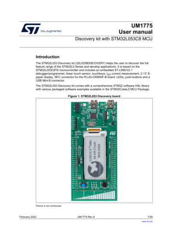
1. Quick StartDIsco is a dynamic Teledyne Isco D-series syringe pump control interface developed forWindows using LabVIEW. The base functions of DIsco enable RS-232 (serial)communications for remotely controlling and monitoring any number of Teledyne Iscopumps (currently verified for up to 6 pumps). Data acquired from the pumps can beplotted near real-time to aid the user with process monitoring and also saved in a commadelimited ASCII text file. The more advanced features of DIsco include custom pumproutine development, external data fetching, and manual serial commands.1.1 InstallationDIsco includes an install file called "Setup.exe" which contains all the requiredLabVIEW divers necessary to run the program on a Windows operating system. IfLabVIEW is prior installed, it is recommended that a custom install directory is selectedto avert potential compatibility issues. Installation can take some time to complete. Theread/write security settings of the default install directory can interfere with full featuredexecution of DIsco. After installing the program, it is recommended that the DIsco installfolder be set to allow both read and write access (requires administrative access). Contactyour local IT to ensure that this setting is compatible with your local securityrequirements.1.2 StartupInitial execution of DIsco gives includes a routine to automatically detect and begincommunication with any Teledyne Isco D-series pumps that are attached to yourcomputer. This routine searches for active RS-232 serial ports on your computer thenpolls each port searching for compatible pumps. The current version of DIsco is defaultconfigured for a baud rate of 9600 which typically provides for stable communicationwith the Teledyne Isco Legacy Controllers and is therefore recommended. Consult themanufacturer's manual for the procedure to change the baud rate if needed.Communication with the pumps is established automatically if any pumps are detected.The serial port communication information is saved in a text file named "Settings.csv"that is created in the DIsco install directory and can be manually edited if needed.Subsequent startups of DIsco do not require that you automatically detect pumps but thisfeature is available in the event that any hardware changes have occurred. Note that baudrates other than 9200 can be used if desired, these settings are manually accessed in"Settings.csv".1.3 Exiting DIscoAt the top-right of the main window is a red "Exit" button. This button saves the DIscoprogram settings for future restarts and is therefore the preferred method for closingDIsco. The standard Windows close button is also included at the top right if the userdoes not want to save the current settings.1.4 Main window overviewThe front panel of the program is shown below (Figure 1). The main window is arrangedinto four general panels including the output panel, the pump control panel, themonitoring panel, and the advanced control panel. This arrangement is fixed in this3
version of DIsco and therefore cannot be adjusted. Tooltips are provided in DIsco toassist user identification of the various available controls and their functions.Figure 1. Main window of DIsco operating two pumps via one pump controller. Thiswindow is organized into four main panels being (top) the output panel, (left) the pumpcontrol panel, (center) the monitoring panel, and (right) the advanced control panel. Thetop left provides DIsco status indicators and a UTM timestamp, intended for debuggingand synchronization purposes.1.4.1 Data output (saving)Data saving is accessed in the output panel with the default setting being "Not SavingData". To activate data saving it is recommended that you first specify a directory andfilename then click the "Not Saving Data" button. The button then changes to "SavingData" and is green in color, indicating that data is now being saved. All data saving isconfigured as appending to reduce the risk of overwriting any existing data and to preventdata loss in the event of hardware/software crashes. The save function is configured to4
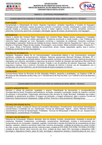
create comma delimited text files with up to 10,000 rows (i.e. line returns). For longerdata sets, additional files are created with incrementally increasing names.Example data output from DIsco with two pumps and one controller is provided ,H,H,H.The sequence of this data is as follows:(0; leftmost column) empty time column(1) date stamp in 0/0/1900 00:00 UTM format(2) pump index 0 pressure in kPa(3) pump index 0 flow rate in mL/min(4) pump index 0 volume in mL(5 to 7) pump index 1 pressure, flow rate, and volume(8) pump index 0 status(9) pump index 0 control status(10) pump index 0 error status(11 to 13) pump index 1 status(14 to 21) valve status controller index 0Expanding the system for more pumps adds the additional pump data in order followingthe respective index numbers. Adding additional controllers adds additional sets of 8valve status indicators.1.4.2 Basic pump controls by indexBasic pump and valve controls are accessed by the pump control panel (Figure 1: left;Figure 2). Perhaps most important function is the large "Stop All" button which can beused to quickly stop all pumps that DIsco is communicating with. The target pump beingcontrolled is specified by pump index (top-left of panel). Switching between pumpindices refreshes the corresponding input boxes and updates the displayed status values tomatch the respective selected pump. A pump naming feature is included to aid useridentification of the different pumps in the system. In this example (Figure 2) the selectedpump has been named "Charlie".5
Figure 2. Basic pump controls accessed in the pump control panel. Note that pumps andvalves have index selectors to aid control of multi-pump systems (more than 3 pumps;more than 1 controller). The valve index selector can be tied to the pump index selectorusing the "Match Pump Index" checkbox to simplify control as suitable for somesystems.The basic pump information includes the pump type (e.g. "65DM"), pump letter (e.g."A"), and call ID (e.g. "0"). The pump type aids identification in multi-pump systems andverifies good communication. Refer to the troubleshooting section of this manual if thepump type displays as "Unknown". The pump letter refers to the position of the pumpconnection on the back of the pump controller. Note that all controllers require a pump"A" and built in continuous constant flow/pressure capabilities (referred to as "CCF" and"CCP" in DIsco) require that both pumps "A" and "B" have matching type. The Call ID isa DIsco index reference uniquely matching pumps with their respective controllers. Thisnumber is used when accessing controls such valves (i.e. digital voltage outputs).Setpoint controls include target pressure and flow rate setpoints. The associated valuesare changed via the corresponding buttons to the right of each input box. Positive flowrate values are used to specify outflow and negative flow rate values are used to specifyrefill rates. Take care when changing the setpoints while the respective pump is running("R" or "F") in constant flow mode ("CF" or "CCF") because switching from positive tonegative values will reverse the pump flow (and vice-versa). This behavior differs fromthe standard pump function as intended per the manufacturer but simplifies controls. Softlimits are included in DIsco to override invalid setpoint values. These soft limits are setaccording to both the user specified limits and the physical limits per pump type. Notethat it is possible to command flow rate and pressure setpoints outside the physical limitsof a given pump via serial communication. These soft limits are intended to prevent suchinvalid commands from being passed to the pumps, thus helping prevent accidentalfailures.6
Pump status readouts include the most recently acquired (serial) pressure, flow rate, andvolume information as well as the operational state, control status, and error state of thepump. The operational state, control status, and error state are printed as single charactervalues in the output data (save file) but are interpreted in DIsco as plain text for the easeof the user. In this example, "Charlie" is currently filling ("F") at approximately 3.7mL/min and it being remotely controlled ("R") with no errors ("-"). The control mode isindependent constant flow ("CF"), so control of pump "A" is not automatically tied topump "B". Note that the manufacturer's current serial communication protocol cannotidentify the current control mode of the pumps so this is unknown by default when DIscois started up. While DIsco is running, it is assumed that the user is changing the controlmode solely using DIsco (not manually via the pump controller).Advanced functionalities of DIsco include the ability to program pump routines. If aroutine is running, this is indicated in the pump control panel as gentle reminder for theuser.The pump control mode can be set using the pump mode configuration buttons. Theavailable modes include: CF: Constant flow rate control mode (direct) CP: Constant pressure control mode (via PID) CCF: Continuous constant flow rate control mode (direct using pumps "A" and"B" along with remote controlled valves) CCP: Continuous constant pressure control mode (via PID using pumps "A" and"B" along with remote controlled valves)The pump can be enabled to run using the "Run" button. The pump can be stopped(individually) using the "Stop" button. The pressure reading can be digitally zeroed usingthe "Zero Pres" button. The control state of the pump controller can be toggled using the"Remote"/"Local" button, switching state when clicked.1.4.3 Valve (digital output) controls by indexThe DIsco valve (digital output) controls include two functionalities, position and controlstate. Valve positions can be set manually at any time using the "Set V Pos" button. Thisbutton sets all valves on the controller to match the positions specified by thecorresponding (upper) check boxes. When using the Teledyne Isco valve hardware, adigital high output ("H") closes a valve and a digital low output ("L") opens a valve.These positions can differ for custom built valve or digital control systems. By default,the Teledyne Isco pump controller will switch the valve positions automatically when thepump is running ("R"), filling ("F"), or stopped ("S"). This automated control state isreferred to as internal control ("I"). In some cases, it is beneficial to disable this automaticcontrol and instead control the valves manually using DIsco, this option is referred to asremote control ("R"). The control state can be specified for each valve separately usingthe "Set V Ctrl" button or toggled for all values using the adjacent "Internal"/"Remote"7
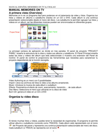
button. Refer to the Teledyne Isco pump manual for more information on this topic. Acheck box labeled "Match Pump Index" is provided if the user desires the controllerindex (for valve control) to be linked to the selected pump index.1.4.4 Monitoring panelThe monitoring panel includes an XY-plot and a pump status table. The plot includeslinear and semi-logarithmic scaling capabilities that are well suited for pressure and flowrate monitoring, respectively. The status table concisely gives the most recently acquireddata and status for all pumps in communication with DIsco. In this case, two pumps areconnected named "Charlie" and "Anna" with index references of 0 and 1 respectively.Up to four linear series and two logarithmic series can be plotted at a single time. Therelevant system variables actively used for plotting are stored locally in a history arraythat is shown in the output panel (Figure 1). The plot display can be adjusted using theplot settings options which includes selection options for the plotted variables (by color).The abscissa (x-axis) can be user configured to plot against any variable with the defaultbeing "Time" with units of minutes. The default system variables that are commonlyuseful for plotting are given in Table 1. A full list of the available variables for plotting isviewable in the advanced control panel "Vars" tab. Note that the semi-log plot permitsplotting the logarithm of positive, zero, and negative values with respect to user-setminimum and maximum absolute values. Positive logarithmic values are plotted abovethe indicated reference line (white), negative values are plotted below, and zero(minimum) values are plotted on the reference line. This differs from conventionallogarithm plots which do not allow viewing log(0). The formula used for the logarithmicseries varies with plot-scale and is displayed in the advanced control panel "Settings" tab.Table 1. Common DIsco variables used for plotting.Variable PrototypeParameterV#Pump volume (mL)P#Pump pressure (kPa)Q#Pump flow rate (mL/min)TimeTime (min)DateDate (days); 1900/0/0 UTM8Example (pump index 0)V0P0Q0TimeDate
Figure 3. Pump monitoring panel for customizable data visualization and full systemstatus monitoring.9
2. Advanced ControlsAdvanced syringe pump users may desire custom pump control methods specific to agiven application. For example, the pressure in pump "B" for a given procedure may needto be 500 kPa less than the pressure in pump "A" at all times. Or perhaps the combinedflow rate of pumps "A" and "B" must be managed to achieve a given displacement rate asmeasured by an auxiliary LVDT. DIsco was designed with such capabilities in mind andsome example pump routines are included. Additionally, some basic DIsco customizationfeatures are available through the settings options.2.1 DIsco settingsThe advanced control panel includes settings for startup and exit, data calling, andinformation regarding the status of custom pump routines that can be of use fordebugging.2.1.1 Data call rateThe data calling rate is the frequency with which DIsco requests the status of the pumps.A readout below this setting gives the most recent elapsed data call time (in milliseconds)as a reference for determining a suitable maximum data call rate. A suitable maximumdata call rate can be calculated as:Max Call Rate 10002 Call Execution Time 300(1)This call rate can be accelerated in a multi-pump system by consolidating pumps onto asfewer controllers as possible. Each controller typically consumes 200 to 350 ms whenpoled for status, regardless to the number of pumps attached.2.1.2 Logging and data recoveryDIsco includes a secondary data logging system intended for debugging. This systemlogs all commands passed to the pump controller along with the replies from thecontroller. The format of this file is comma delimited but otherwise raw with respect toparsing and interpretation of the replies. Interpretation of this file requires knowledge ofthe DASNET command protocol that the pumps use to communicate as well asfamiliarity with the advanced functions unique to DIsco. In the event of data loss fromthe primary file saving system, there is a possibility that the data can be recovered fromthe DIscoLog files. An option exists to disable this secondary log to speed up DIsco andprevent excess data accumulation.2.2 Manual commandsManual pump commands in DIsco enable access to most DASNET serial commands,including the lesser used and more advanced pump controls. For convenience, thecommands can be typed in directly or looked up from an indexed list complete withdescriptions of the command. When relevant, manual commands are executed withreference to a pump index that is also located in the manual command tab. Some manualcommands (e.g. "SQ ") require passing values that can be entered in the provided“Append” text box. Table 2 summarizes the available manual commands in DIsco. Note10
that limit settings (e.g. "UP ") are restricted to maximum or minimum values per thepump type. Caution: if the pump type is “Unknown” the pressure, flow rate, and volumemaximum limit settings are assumed at 13790 kPa, 25 mL/min, and 1015 mLrespectively.Table 2. Manual and custom routine commands available in DIsco.CommandCLEARPassing Value-CLEAR ALLSTOPSTOP ALLRUNREFILLCF MODECP MODECCF MODE-CCP MODE-SQSQ SPSP ALOGDoubleDouble-DIGITALDIGITAL GET ALL8 character string of H's andL's2 character string of integerand H or L8 character string of R's andI's-IDENTIFY-LIMITS-LQ UQ LP UP PID DoubleDoubleDoubleDouble-MQCP LOCALLOCAL ALLREMOTEREMOTE ALLZEROSUBDoubleRoutine's nameGOTOVARIABLE ALERTUNITS See in-program descriptionMath expressionDoubleSee pump manualSINGLE DIGITAL DIGITAL CTRLDIGITAL CTRL DescriptionStops all pumps on the pump's controller and resets thecontroller settingsStops all pumps and resets settings on all controllersStops the specified pumpStops all pumpsActivates the specified pump in its respective modeRefills the specified pump at maximum rateEnables constant flow rate mode on the given pumpEnables constant pressure mode on the given pumpEnables continuous constant flow rate mode on a pump "A"and "B" pair; requires that the command references the pump"A" indexEnables continuous constant pressure mode on a pump "A" and"B" pair; requires that the command references the pump "A"indexRequests the current flow rate setpointSets the flow rate setpoint (mL/min)Requests the current pressure setpointSets the pressure setpoint (kPa)Return status of an analog voltage input for specified pump'scontroller. Format: Integer 1-5.Requests the valve position status (high or low)Sets the (valve) positions for all 8 digital outputs from acontrollerSets the (valve) position of a single digital output from acontrollerRequests the valve control status (internal or remote)Sets the (valve) control status for all 8 digital outputs from acontrollerRequests the status of the pumps on the specified pump'scontrollerRequests the model information for all pumps connected to acontroller.Requests the pressure and flow rate limits set on a specifiedpumpSets the lower flow rate limit on a specified pumpSets the upper flow rate limit on a specified pumpSets the lower pressure limit on a specified pumpSets the upper pressure limit on a specified pumpEnables or disabled PID pressure control. 0 or 2 for disable, 1(default) for enable.Sets the maximum flow rate for constant pressure control modeDisables remote (serial) control of a pump controllerDisables remote (serial) control of all pump controllersEnables remote (serial) control of a pump controllerEnables remote (serial) control of all pump controllersZeroes the pump's pressure readingEnters into a custom pump subroutine (used in pump routineprogramming)A conditional goto command used for if statements and loopsSets a custom variable value using a mathematical expressionEmits and audible two-tone alertWarning: Do not change the units from mL, min, and kPa11
2.3 Variables and mathThe "Vars" tab can be used to view and edit variables inside DIsco. All variables arestored in DIsco as a name string and an accompanying double value. A collection ofvariables (e.g. "Time") are standard and automatically updated through data calls andother commands. New variables can be created using programmatic mathematicalexpressions. For example, "Var01 13.17" will create a variable named "Var01" with avalue of 13.17. As a subsequent example, "Var02 Var01-sin(Time/4)" will create avariable named "Var02" and assign it a value as calculated from the right-hand-side(RHS) expression "Var01-sin(Time/4)". In this example, "Time" is a standard variablethat is updated with every data call, "sin(.)" is a built in function, and "Var01" is takenas the value 13.17 per the previous example. If Var02 already exists, it's valueoverwritten with the evaluated RHS expression. Note that overwriting standard variableswill not change their respective control values and is therefore not recommended.The current functions (not case sensitive) available in DIsco for mathematicalexpressions are the following: abs() sin() cos() tan() asin() acos() atan() sign() int() ln() log(): base 10 exp() else: return value in parentheses with no functionOperators and order of operations are interpreted in the following sequence: (): parenthesis **: power : power *: multiply /: divide -: negate -: subtract : add12
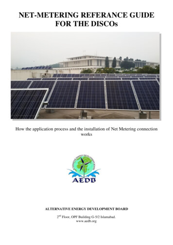
Numbers can be expressed as integers or as doubles with the following notation: 13: positive integer 13.17: positive double 13.1756E78: large double scientific 8.7654E-32: small double scientific -13: negative integer -13.17: negative double -13.1756E78: negative large double scientific -8.7654E-32: negative small double scientificThe current interpreter implemented in DIsco does not have any functionality to alert theuser of invalid expressions and will consider all expressions as valid. Due to this, it isencouraged that you verify the results from an expression using the manual "Vars" tabagainst alternative software.Variables can be used as the passing value for any manual commands that pass a doublevalue. For example, the manual command "SQ " can be passed "Var01", thereby settingthe current flow rate setpoint to 13.17 per this example. The utility of this functionality isdirectly relevant to custom pump routine programming.Note that any variable can be plotted in the monitoring panel simply by inserting it'sname into the plot settings. Once inserted, the value of the variable will be recorded withevery data call in the data history array that can be viewed in the output panel.2.4 External data referencingExternal data referencing is a feature of DIsco by which data outputs from otherprograms can be read in and stored as a special type of custom variable. This feature isaccessed in the "External" tab. This feature expects appending comma delimited text filesto operate properly. Imported data is parsed into a 2D array where columns are assumedto be channels and rows are assumed to be sequential entries (i.e. time series). “Add NewColumn ” stores the value from the last row of a specified column (external text file) inDIsco as a special variable. This value is subsequently updated (queried) at the Data CallRate. Hence, measurements from data loggers external to DIsco can be integrated withDIsco functions. Errors can occur between DIsco and the external program if bothattempt to access the same file at the same time. In this event, DIsco will temporarily skipthe external data query and resume without interruption. However, DIsco accessing thefile can sometimes cause the external program to crash if the external program doesn'thave file access error handling.2.5 Pump routinesThe most advanced capabilities of DIsco are developed using pump routines (Figure 4).Pump routines are handled by a comma-delimited file import-export. By default, pumproutines are expected to be stored in a folder named "programs" that is located in theDIsco home directory. All *.csv files located in this directory are automatically loadedinto DIsco on startup and are accessible for execution as well as editing. Routines can be13
written in DIsco or using external programs and then imported using the "Import CSV"button. This capability is makes routine sharing between users simple and easy.Figure 4. Pump routine editor and controls.Custom pump routines are written in a four column format. The first (leftmost) columnspecifies a manual command (c.f. Table 2). The second column specifies the index of thepump that is to be commanded, in this case pump index 0 (i.e. "Charlie"). The thirdcolumn specifies a wait timer with the default value being 0 milliseconds if not otherwisespecified. The fourth column is used for passing values. Any additional columns are notinterpreted and can therefore be used for comments. An example pump routine for sinewave pump flow (c.f. Figure 3) is shown below:VARIABLE ,,,FlowRange 5.0,VARIABLE ,,,FlowPeriod 0.5,VARIABLE ,,,Pi 4*atan(1),STOP,0,1000,,CF MODE,0,,,VARIABLE ,,,StartTime Time,VARIABLE ,,,SinFlow Q ,0,,SinFlow,RUN,0,,,VARIABLE ,,,SinFlow Q ,0,,SinFlow,GOTO,,100,-003 Time 0,After selecting a routine, it can be installed into DIsco and executed. This method ofimplementation enables pump routine editing without interruption of data acquisition, afeature that can be beneficial for long term studies. Note that manual manipulation ofvariables and pump settings outside the pump routine can be used to further enhance theutility of a given routine. Also, the wait timer or use of the Date variable can be used forprogrammatically scheduled changes in the pump states.14
3. Manually editing the settings fileIn some situations, it may be necessary to manually set the pump connection informationby editing the "settings.csv" file. An example "settings.csv" file as viewed with Notepadis shown below. The settings are delimited with commas, semi-colons, and line returns.The first line specifies the serial communication settings with a single pump entryhighlighted below. Each entry (separated by semi-colons) contains the followinginformation in order (separated by commas):1. Pump name (user specifiable string)2. Pump position on controller ("A", "B", "C", or "D")3. Pump serial port number ("1" COM1)4. Controller baud rate (9600 recommended and default)5. Controller identification number (1-6; set by the controller's serial option menu)6. Pump type (e.g., "65DM")7. Call index number (automatically optimized at startup)Manually setting the pump serial connections requires properly specifying (2) the pumpposition (‘A’, ‘B’, ‘C’, or ‘D’), (3) serial port number, (4) baud rate, (5) and controlleridentification number for each desired connection. Other settings are automaticallyupdated or can be manually updated while the program is running. Note that any edits to"settings.csv" should be completed prior to startup.15
4. Basic TroubleshootingProblemPump controller is beepingand DIsco is not respondingCauseThe pump controller is in asub-menuAUX never illuminated /CALL always illuminated /data acquiring but no othercommands functionINIT light not turning offAcquisition rate is too fastWARN light is illuminatedCOM light is illuminatedERR light is illuminatedValve positions changewithout command/ whenpumps are stopped/ whenactivating runPumps are refilling tooslowlyInitial startup is occurringbut taking some timeA serial communicationfailure occurred duringstartupIntermittent serialcommunications failures areoccurringIntermittent serialcommunications failures areoccurringValve internal control isenabledPatienceFlow rate set point is toolowSet the flow rate to a greaternegative valuePumps in CP/CCP mode are Maximum flow rate limit innot flowing quickly or at all constant pressure mode isbut are runningset too lowPlot is plotting nothingFixPlace the pump controlleron a home screen such asthe select pump menu;restart DIscoReduce the data call rate in"Settings" tabPlot settings are incorrect16Restart DIsco; check serialcabling; check hardwaredriversCheck serial cabling; checkhardware driversThe custom pump routinemay have had an error;routine reset recommendedToggle valves to remotecontrol and set positionsmanuallyAlternate: send the manualcommand
manufacturer's manual for the procedure to change the baud rate if needed. Communication with the pumps is established automatically if any pumps are detected. The serial port communication information is saved in a text file named "Settings.csv" that is created in the DIsco install directory and can be manually edited if needed.