Transcription
LESSONS LEARNEDEvolution of the Protected IntersectionDecember 2015PREPARED BY:Alta Planning Design711 SE Grand AvePortland, OR 97214iii
CONTRIBUTORSJoe Gilpin, PrincipalNick Falbo, Senior PlannerMike Repsch, PEAlicia Zimmerman, PEAlta’s mission is to createactive communities.Founded in 1996, Alta Planning Designis North America’s leading multimodaltransportation firm that specializes in theplanning, design, and implementation ofbicycle, trail, pedestrian, park, and transitcorridors and systems. Alta Planning Design, 2015.Lessons Learned: Evolution of the Protected Intersection by Alta Planning Designis licensed under a Creative Commons Attribution-NoDerivatives 4.0 InternationalLicense.Disclaimer: The dimensions, design details, recommendations, and findings in thisdocument are based on theoretical and conceptual analysis and design. In developingthe document’s recommendations, the authors utilized prior experience, professionaljudgment, and industry standards where available. While construction of protectedintersections in the U.S. was recently completed, empirical data on these intersectionsis not yet available to substantiate the report’s recommendations. Engineeringjudgment should always be used in site-specific intersection design.iv
TABLE OF CONTENTS01 Introduction02 History03 Planning and Policy04 Elements of a ProtectedIntersection05 Geometric Design06 Large Vehicle Accommodation07 Signal Operations08 Case Studies09 Referencesv
Davis, CAvi
01 IntroductionThe evolution of North American bikeway design hasprogressed to protected intersections.Following the publication of the National Association of City Transportation Engineers(NACTO) Urban Bikeway Design Guide in 2011, Mark Wagenbuur, an engineer from Den Bosch,Netherlands, author of the Bicycle Dutch blog, published this video asking both NACTO andNorth America as a whole if this guide was really the best we could do. Using our own graphicsand renderings, he dissected our geometry and built a “Dutch Junction” design, demonstratingits advantages. As of 2015, this video has been viewed over 300,000 times.Exhibit 1Screenshot fromJunction Designthe Dutch CycleFriendly Wayhttps://youtu.be/FlApbxLz6pA(Wagenbuur, 2011)Yes, it was true, NACTO did not include the treatment in the Urban Bikeway Design Guide. Wasit because we didn’t think it was worthy? No. It was because any treatment in the NACTO UrbanBikeway Design Guide had to pass three tests:1) Has it been implemented in the United States/Canada?2) Was there any experimental data or research that showed its impacts to safety oroperations?3) Has the North American experience provided enough lessons learned to inform andimprove future implementations of the design?At the time, none of these conditions were met. Today, this is no longer true.During our work on the development of the NACTO Urban Bikeway Design Guide, Alta staff didsee merit in the Dutch junction style design and have spent subsequent effort studying it andattempting to create a framework for adapting it to the North American roadway context. Afterall, North American drivers have different culture and training than our Dutch counterparts.We typically drive larger vehicles and have different expectations for signaling. For example,right turn on red is not allowed in the Netherlands; in much of North America, it is rare to see itdisallowed.First, what was needed was a piece of salesmanship to show what the design could be in anNorth American context and inspire designers, engineers, planners, and everyone else toinnovate. Enter www.protectedintersection.com. This website and video, shown in Exhibit 2,spread quickly across the Internet after publication by one of Alta’s staff.1
Exhibit 2Screenshotfrom ProtectedIntersections intersection(Falbo, 2014)While the video sold the concept, it also raised a number of unanswered questions. Howdo large turning vehicles navigate the geometry? Is it compatible with the Americans withDisabilities Act (ADA)? How do you create “bicycle-friendly signal phasing”? In this publication,we attempt to answer many of these questions and share this knowledge.Through our work designing Salt Lake City’s first protected intersection, Alta engineersand designers have explored the research status, regulatory implications, and fundamentalgeometric design principles surrounding the protected intersection design. We share theresults of this exploration here in the hopes that more jurisdictions will adopt the design to raisethe safety and comfort of their current and future bikeway designs.As of December 2015, there are six locations in North America that qualify as protectedintersections. The protected intersection is fast becoming an accepted and implementedtreatment type and would meet NACTO’s tests for inclusion in the next edition of the UrbanBikeway Design Guide.This white paper was internally funded at Alta Planning Design through a program calledthe “Alta Incubator.” Alta staff compete each year for the chance to spend company funds onfurthering the state of the practice with regard to active transportation. Over time, cities andurban practitioners will continue to innovate and learn more about implementing protectedintersections. As this experience expands, we will update this publication periodically with newexperience, design guidance and case studies.We hope this is a useful document, and we look forward to working with others implementingmore of these amazing facilities. Joe Gilpin, Vice President2
02 HistoryThe protected intersection design with corner safety islandsemerged in the Netherlands and other northern Europeancountries as an approach to define traffic movements at theintersection of two separated bike lanes.A Forgotten ConceptEngineers in the United States were aware of this design as early as 1972. The 1972 Instituteof Transportation and Traffic Engineering (ITTE) at the University of California-Los Angelesconducted a study of the most feasible methods to safely accommodate bicycle riders onU.S. streets on behalf of the California State Senate. The report, Bikeway Planning Criteria andGuidelines, included a variant of protected intersection design, shown in Exhibit 3. The reportdescribed this as the “Recommended Intersection Design for Intersecting Arterial Roads withBikeways on Each Road.”That same year, a more localized report prepared for the City of Davis and University ofCalifornia – Davis was the Davis Bicycle Circulation and Safety Study. Like the ITTE report,the Davis study identified the design of an “Offset Pathway Crossing” modeled after Germandesign as a strategy to adjust approach angles for increased visibility.The Davis study reflected briefly on the required deflection of bicycle riders from a straightpath, and concluded that “Experimentation with these designs is necessary to determine theirsafety-effectiveness under North American traffic conditions.”Exhibit 3Design Diagramsfrom 1972 BikewayGuidelinesThe 1972 Institute ofTransportation and TrafficEngineering at UCLA,Bikeway Planning Criteria andGuidelines, called this the“Recommended IntersectionDesign for IntersectingArterial Roads with Bikewayson Each Road.”3
Contemporary U.S. GuidanceSeparation distanceTable 3Contemporary bicycle facility design guidance does not address all of the iskroadwayandThetrail(Figure10)intersection designas elementsmitigatingto bicyclists.cornersafetyisland and setback bicycle crossings are not directly featured in the AASHTO Guide for thehas a pronounced effect on operations. At issue is:Development of Bicycle Facilities or the NACTO Urban Bikeway Design Guide. The NACTOUrban Bikeway Design Guide does discuss the use of pedestrian safety islands in conjunctionwith separated bike lanes and the use of forward stop bars to shorten crossing distance withturning motor vehicle approach speed to the trail;bicycle boulevards.stacking space between the parallel roadway and trail;MototurniSome U.S. researchers and practitioners have noted these design elements in reviews ofpractices.driver recognitionoflimitedthe trail;international bestBecause of theapplication of separated bike lanes, someguidance was ties.trail user recognition of turning motorvehicles; andtrailright-of-wayprioritization.The 1994 Florida DOTTrailIntersection DesignGuidelines had a heavy emphasis oninternational practices and discussed the concept of setback crossings and slow turning speed:MotostackIt is important to control the speed of right turning vehicles, especially when theparallel roadway has a dedicated right turn lane or where there is a large turningTable 3 shows the effects of separation distance on theseradius which both tend to encourage high speed turns.Drivtrailoperations parameters.If a permissive left is in place, the trail should be setback 4 - 10 m (13 - 32 ft)from the roadway to allow motor vehicle stacking space.Trailof mExhibit 4Chanof-w(1m Diagram ofseparationdistance from aroadway near anintersection(Florida DOT, 1994)It is rec 1m toThey aThe NecategorIn 2008, researchers John Pucher and Ralph Buehler published Making Cycling Irresistible:Lessons from The Netherlands, Denmark, and Germany and noted key geometric designfeatures used in northern European counties to create comfortable conditions for bicyclists. OnFigure 10. theTrailspacingthe topic of intersection modifications,authorswrite:near a roadway(1m include3.28 ft)[The intersection junction.designs] generallymany of the following: Special bike lanes leading up the intersection, with advance stop lines forcyclists, far ahead of waiting cars; Insertion of traffic islands and bollards in roadway to sharpen turning radiusof cars and thus force them to slow down when turning right; and Realigning bike pathways a bit further away from their parallel streets whenthey approach intersections to help avoid collisions with right-turning cars.43-6
TURNING MOVEMENTSBend-OutThe bend-out design positions bicyclists downstream on the side street awayfrom the intersection, allowing vehicles to complete turning movements beforeinteracting with bicyclists. This design, which could be used on lower-volumeside streets or driveways, provides space for a vehicle to yield to crossing bicycleswithout blocking through traffic on the main street. A Bicycle/Pedestrian Warning(W11-15) sign may be used as driveways approach separated bike lanes to alertdrivers to be aware for bikes and pedestrians.The 2015 Federal Highway Administration (FHWA)report Separated Bike Lane Planning and Bend-out design provides opportunity A ‘Turning vehicles yield to bikes’01Design Guide established the “Bend-out” design asanappropriatedesign04 insigntheapproachfor anamplepedestrian refuge betweenmay beplaced on the ofthe separated bike lane crossing and themast arm.separated bike lanes at intersections.roadway crossing.02 Separated bike lane and crosswalk maybe raised to sidewalk level through theintersection, providing a traffic calmingeffect.05 For further guidance on typicalsigns and markings for separatedbike lanes, see page 127.The bend-out design positions bicyclists downstream on the side street awayfrom the intersection, allowing vehicles to complete turning movementsbefore06 For furtherguidance on signalphasing, see page 119.03interacting with bicyclists. For further guidance on buffer selectionand installation, see page 83.Bend-out design provides opportunity for an ample pedestrian refuge betweenthe separated bike lane crossing and the roadway crossing.[Recommended bend-out distance of] 15-25 ft (4.5 - 7.5 m)Exhibit 5Figure 26“Bend-out” designrecommendation forseparated bike lanesat intersections(FHWA, 2015)NOT TO SCALEMost recently, the 2015 Massachusetts DOT Separated Bike Lane Planning & Design Guide has111embraced the protected intersection design as the preferred treatment at intersections withseparated bike lanes.“Bicycle and pedestrian crossings set back from the intersection create spacefor turning motorists to yield to bicyclists and pedestrians. Research has foundcrash reduction benefits at locations where bicycle crossings are set back fromthe motorist travel way by a distance of 6 ft. to 16.5 ft. (2 - 5 m)”“Protected intersections are preferable to mixing zones. Mixing zones are generallyappropriate as an interim solution or in situations where severe right-of-way constraintsmake it infeasible to provide a protected intersection.”Exhibit 6“Bend-Out” design inadvance of a protectedintersection(MassDOT, 2015)5
Chicago, IL (under construction)6
03 Planning and PolicyConventional bike lanes, shared roadways, or bicycleboulevards can be brought into the protected intersectiondesign by transitioning the bikeway into short separated bikelane segments upstream of the intersection. The protectedintersection design is applicable at both signalized and stopcontrolled intersections.Planning Level Space RequirementsTo achieve the desired setback crossing design, protected intersections may require morespace in the immediate vicinity of the intersection than intersections with conventional facilities.This space requirement is dictated by a number of factors, including lane configuration,presence of parking, and turning radius requirements.When designing a protected intersection, roadside dimensions and intersection right-of-wayare more of a controlling factor than total roadway width. Exhibit 7 illustrates the roadsidespace and/or corner right-of-way is necessary to implement corner safety islands and offermaneuverability, queuing storage, and separation between modes.Exhibit 7Wide RoadsideNarrow RoadsideWide roadside environment offer ampleroom to position safety islands and setback the bicycle and pedestrian crossingswithin the right-of-way limits.Narrow roadside environmentswith minimum dimension sidewalksand separated bike lanes offer littleextra space for maneuvering orqueuing within the right-of-way.Acquisition of additional right-ofway at corners may be necessary.Roadsideright-of-wayNarrow roadsideenvironments mayrequire additional rightof-way at corners inorder to meet preferreddesign dimensions of aprotected intersection.7
Policy ConsiderationsLarge Vehicle Accommodation PolicyA key design feature in protected intersections is geometry designed to slow driver turningspeeds. This geometry may be incompatible with some classes of large vehicle movements.Truck accommodation and design compatibility issues may be addressed through a nuancedtruck accommodation policy including different classes of truck networks and design vehicles(ITE, 2011).See Section 06, Large Vehicle Accommodation, for more discussion on design strategies.Layered NetworksThe layered network approach to truck accommodation can encourage large trucks oncertain routes but not others. On high-priority bicycle routes, it may be appropriate toprovide an alternate route for large vehicles to prevent or minimize intermodal conflicts.Prohibiting turning for some large vehicles may also be an option where it cannot be safelyaccommodated.Design and Control VehiclesThe NACTO Urban Street Design Guide (NACTO, 2013) offers guidance on the challenges of“designing for” large vehicles versus “accommodating [large vehicles] as an infrequent user”.Curb radii designed to accommodate the largest possible vehicle will result in significantcompromises in protected intersection design. If turning is allowed, drivers of large vehicles aretrained to take unconventional paths through intersections when needed.Non-Compliant Signalization PhasingFHWA Interim Approval 16 (IA-16) identifies national direction on bicycle signal installation andidentifies key restrictions on their use. These restrictions include: Bicycle signal faces may not be used concurrently with conflicting vehicular phases. Thisrestricts bicycle signals from being used as a leading phase; however pedestrian signalsallow this. IA-16 prohibits bicycle scramble phases. It is unclear if this would apply to a protectedintersection as bicyclist mixing would happen prior to entering the intersection. A scramblephase for bicyclists in the context of a protected intersection has more similarity tocirculation through a roundabout than an an open intersection with many possible paths oftravel.See Section 07, Signal Phasing, for more discussion on signalization approaches and IA-16compliance.8
Right Turn on RedThere is no current research or consensus on whether right turns on red should be prohibited inprotected intersection designs. The greater distance a right-turning vehicle would have to travelto enter the traffic stream on the cross street may make restrictions a prudent design decision.The presence or lack of dedicated right turn lanes may also influence this decision, as will thenumber of turning vehicles that is to be accommodated.See Section 07, Signal Phasing, for more discussion on right turn on red.Accessibility ImplicationsThe application of the protected intersection design does have pedestrian accessibilityconsiderations. In the scenario of introducing a separated bike lane “traveled way,” it couldbe interpreted that detectable warnings would be needed to define the edge of this traveledway. This scenario is not unlike a free right lane for cars where pedestrians have priority.Alternatively, the City of Davis, California, has chosen to make the corner areas a sharedbicycle/pedestrian area through the application of shared-use paths rather than exclusiveseparated bike lanes and parallel pedestrian sidewalks. These strategies may have implicationson the minimum allowable pedestrian signal phase. Additional issues with these twoapproaches include: Location of the pedestrian push button (if signal does not rest on recall) within thepedestrian refuge island versus behind the separated bike lane. This decision may haveimplications for minimum calculated crossing timing. One possible advantage of aprotected intersection is the potential for lowering the necessary pedestrian crossing timingversus a wider intersection. This could result in the option of shorter cycle lengths, or lessdelay for all users. Whether bicyclists and pedestrians are separated in their respective waiting areas with aphysical barrier.9
Salt Lake City, UT10
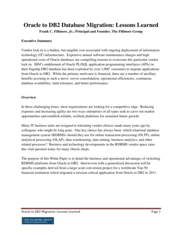
04 Elements of a Protected IntersectionProtected intersections use a variety of design elements tocreate safe, comfortable conditions for bicyclists, illustratedin Exhibit 8. While not all of these elements are required inall situations, they make up the typical protected intersectionexperience.Exhibit 8Visual illustrationof key protectedintersection featuresCorner safety islands havemultiple roles: offeringa protected place forbicyclists to queue whencrossing and turning, andmanaging the speed ofturning vehicles whenpermitted turn conflicts alOperationsPedestrianSafetyIslandSpecial attention shouldbe paid to the amount ofdeflection required for bothpedestrians and bicyclists inadvance of the intersection.CornerSafetyIslandForwardStop BarCornerApronYield toPedestrians11
Exhibit 9Description ofkey orner Safety IslandA corner safety island is a raised area thatseparates the separated bike lane from thegeneral purpose travel lane and defines thecorner radius of the intersection. The islandprovides comfort for waiting bicyclists and maymanage the speed of turning vehicles.Corner ApronA corner apron is an optional traversable partof the corner safety island that may be neededto accommodate the wheel tracking of largevehicles.Forward Stop BarThe forward stop bar marks the location atwhich bicyclists are intended to stop and waitat a red signal indication.Approach TaperThe separated bike lane may shift in advanceof the intersection to align bicyclists with thesetback bicycle crossing. This taper should besubtle to minimize impacts to bicyclists.Yield for PedestriansBicyclists should yield to crossing pedestriansat the location of pedestrian crosswalks priorto progressing to the forward stop bar. Yieldline markings and signs should identify thisrequirement.Pedestrian SafetyIslandThe pedestrian safety island is installedbetween the separated bike lane and generalpurpose travel lanes, allowing pedestrians toqueue on a DON’T WALK signal and shortencrossing distance of the roadway.Setback BicycleCrossingTo improve sightlines and clearly establishpriority, the bicycle and pedestrian crossingsare set back from that of the adjacent throughtravel lanes.Bicycle SignalOptimizationVarious signal phasing schemes may be usedin combination with geometric design tomitigate or prevent conflict between bicyclists,pedestrians, and turning motor vehicles.
Exhibit 10Summary ofbenefits d roadway crossingdistance.Reliance on bicyclists yielding topedestrians with right of way.Slower driver speed reducecollision severity and increasesyielding to crossing pedestrians.SafetyProvide more reaction time forall users to detect and correctfor mistakes due to lower vehiclespeed.May increase difficulties forindividuals with vision disabilitiesdue to the potential for pedestrianpath deflection and challengesin detecting adjacent movingbicyclists.OperationsShorter bicycle and pedestriancrossing distance created by theforward stop bar and pedestriansafety island allow these users toclear the intersection in less time.If right-turn-on red is prohibited, itmay negatively impact capacity.If exclusive bicycle signal phase orleading pedestrian/bicycle intervalsare used, may negatively impactintersection capacity.SpaceMay not require additional right-ofway on streets configured with onstreet parking and wide sidewalks.Many intersections could bereconfigured to be protectedintersections within the existingfootprint.Certain signal phasing schemesmay require an exclusive leftand right turn lane, potentiallyincreasing the physical size of theintersection.Achieving the desired crossingsetback distance from theroadway may require right-of-wayacquisition at corner locations.MaintenanceMay require specialized sweepingand snow removal (if applicable)practices to keep clear of snow anddebris.AestheticsPedestrian safety islands offeran opportunity for low levellandscaping, or placemakingelements such as art or lighting.Results in a cleaner lookingintersection when compared toother intersection treatments suchas mixing zones or bike boxes.13
Austin, TX14
05 Geometric DesignDesign elements are common to most configurations,although details differ depending on the bikeway type, laneconfiguration, and intersection signal phasing.Exhibit 11Basic geometricelements and keydimensions of aProtected IntersectionCrossing Setback19.5 ft preferred if ifconflicting turning movements are allowedBicycleQueuing8 x 6.5 ftPreferredCorner Radius20 ft or greater basedon control vehicleApron Radius(If applicable10-20 ft based onpassenger carturning speedPedestrianIsland6.5 - 14 ft10ftmin.Approach TaperFor smooth transitionto setback crossing15
Setback CrossingIf permissive turns are allowed across the separated bike lane, it is important to provideadequate setback area to encourage maximum visibility, proper motor vehicle yielding, andefficient operation.U.S. guidelines for setback crossings in roundabouts identify 19.5 feet (6 m), about one carlength, as the preferred setback distance for yielding prior to crosswalks (NCHRP, 2010). This issupported in U.S. federal separated bike lane guidelines with a recommend 15- to 25-foot (4.5to 7.5 m) setback distance in advance for intersections (FHWA, 2015). 2006 Dutch guidelineson setback bicycle crossings call for 13 to 23 feet (4 to 7 m) depending on context and physicalconstraints (CROW, 2006). More recent Dutch research identifies 16.4 feet as the preferredsetback distance, with 6.5 feet (2 m) identified as a constrained minimum (Fietsberaad, 2011).Setback distances should be selected in conjunction with corner radius dimensions toencourage slow speeds and proper vehicle alignment at the crossing. The angle of approachat the bikeway crossing should be as close to 90 degrees as possible (minimum 70 degrees,AASHTO, 2011).Inadequate setback distances may lead to blockage of the separated bike lane by vehiclesturning right-on-red or blockage of the through travel lane by vehicles yielding to crossingbicyclists. Lane blockage may not be a concern if right-on-red is prohibited and turningmovements are protected through signalization.Exhibit 12Setback bicycle andpedestrian crossingsA setback of 19.5 ft (6 m)provides enough room forone passenger car to yieldto bicyclists and pedestrians,while waiting outside ofthe flow of through motorvehicle traffic.Exhibit 13Narrow setbacks offerinsufficient storageand sight linesSmall crossing setbacksmay lead to blockage ofthe protected bike lane orthrough travel lane.16Crossing Setback19.5 ft (6.0 m)
Corner Safety IslandThe corner safety island offers comfort for bicyclists waiting at the intersection, improvesvisibility of bicyclists to turning drivers, shortens overall crossing distance, and may be used toenforce a specific motor vehicle turning speed.Dimensions of the corner safety island may impact large vehicle accommodation through theintersection and bicyclist queuing capacity. See Section 05, Large Vehicle Accommodation.Turning speed should be limited to 15 mph or less when permissive right turns across the path ofthrough bicycles are allowed. Minimizing turning speeds is important for pedestrian and bicyclistsafety (Fitzpatrick, 2005). Turning speed can be influenced by corner radius, as described inExhibit 14.In roundabouts, an intersection type with similar setback crossing geometry, researchers haveshown that speed has a significant influence over motorist yielding rates, illustrated in Exhibit 15.The AASHTO A Policy on Geometric Design of Highways and Streets discusses the preferencefor low turning speeds at most intersections:. vehicles turning at intersections designed for minimum-radius turns have tooperate at low speed, perhaps less than 15 km/h [10 mph].it is often appropriatefor safety and economy to use lower turning speeds at most intersections.(AASHTO, 2011, pages 3-57)Exhibit 14Horizontal curvespeed and radiusreference chart(AASHTO, 2011,Equation 3-8)V (mph)EF*R (ft)800.38111000.38181200.35271500.3247Values from AASHTO Green Book 2011, Table 3-7 and Equation 3-8The formula for calculating turning speed is R V2/15(.01E F) where:R is the turning radius (effective)V is speed in miles per hour (mph)E is super-elevation. This is assumed to be zero in urban conditions.F is side friction factor100Driver travel speedand yielding ratesat roundaboutcrosswalks.(Geruschat, 2005)Percent YieldExhibit 15500510152025Speed (MPH)17
Forward Stop BarThe inside radius of the corner safety island may impact bicyclist maneuverability and left turnstorage capacity. Maximize the inside radius to allow for smooth transition into the queue areaand to maximize capacity. In the transition area behind the corner safety island areas, provide aminimum of 10 feet (3.0 m) of space between the corner safety island and pedestrian sidewalk.The bicycle stop bar should be clearly marked to identify where bicyclists should wait at ared signal indication or stop sign. The FHWA Separated Bike Lane Planning and Design Guide(FHWA, 2015) provides minimum dimensions of a two-stage turn queue box as 10 feet by 6.5feet (3.0 m by 2.0 m) deep. This may be unachievable and is potentially undesirable to have a 10foot (3.0 m) bike lane gap which may result in use by motor-vehicles. It is particularly importantto clarify the stop location in areas where a corner apron is used to make sure users are waitingoutside of the potential path of large vehicles.Exhibit 16Bicyclist queuingand transition at theforward stop barInside radius10 ft min(3.0 m)18Bicyclist queue area
Pedestrian Safety IslandThe pedestrian safety island should follow standard practices for conventional median safetyislands (AASHTO, 2011).The raised median or crossing island must be at least 4 feet (1.2 m) wide and 6 feet (1.8 m)long to serve adequately as a refuge area for pedestrians, in accordance with Manual onUniform Traffic Control Devices (MUTCD) and American Association of State Highway andTransportation Officials (AASHTO, 2004) guidelines.Detectable warnings are required where users are expected to wait and to identify the point oftransition to the roadway. It is particularly important to clarify the wait location in areas wherea corner apron is used to indicate to users where to wait outside of the potential path of largevehicles.Safety islands in intersection can confuse pedestrians with vision impairments and slow ordelay their crossing. Care should be taken to minimize any change of direction at the safetyisland locations (NCHRP, 2007).Exhibit 17Pedestrian safetyisland in New York, NYThis pedestrian safetyisland simplifiespedestrian crossingsinto two stages andphysically separates theprotected bike lane frommoving motor vehicles.19
Integration with Other BikewaysConfiguration with Mixed-Traffic Bicycle BoulevardsIn some locations, separated bike lanes will cross bicycle boulevards. In these conditions, thebikeway may transition into a separated bike lane in advance of the intersection.Design Considerations Use clear markings and signs to direct users into the separated bike lane portion of theintersection. The entrance to the protected intersection should be located to avoid obstruction byparked cars. The exit to the bicycle boulevard should be positioned to maximize visibility of bicyclists asthey enter the traffic stream.Exhibit 18Configuration withmixed-traffic bicycleboulevardCrossingSetbackMixed traf
intersections. As this experience expands, we will update this publication periodically with new experience, design guidance and case studies. We hope this is a useful document, and we look forward to working with others implementing . more of these amazing facilities. Joe Gilpin, Vice President. Exhibit 2 Screenshot . from Protected .