Transcription
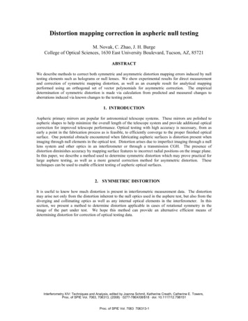
TRANSPORTATION RESEARCH RECORD 14623Rock Correction Issues in CompactionSpecifications for High Gravel Content SoilKENNETHD.WALSH, SANDRA L. HOUSTON, AND GREGORYConstruction control for engineered fills is usually provided by a specification requirement that the in-place dry density of the fill be at leasta specified percentage of a reference dry density. The reference dry density is usually measured by a laboratory compaction test, such as theASTM D698 (Standard Proctor) moisture-density relationship test. Theuse of laboratory determination of the reference dry density for construction control is based on the implicit assumption that the materialcompacted in the lab is substantially equivalent to the material compacted in the field. However, when the fill material contains gravel(material coarser than the No. 4 sieve), this assumption is generally notcorrect. Therefore the contractor and engineer must rely on experiencewith the performance of high gravel content fills at certain specified percentages of a reference dry density, selecting specification requirementsappropriate to individual circumstances. Several methods are availableto account for the effect of the coarse fraction on the reference drydensity, including various rock correction equations and laboratoryscalp-and-replace techniques. Each method may provide a differentreference dry density. The impact of the rock-correction method on construction control is addressed. The results of a survey of several largeconstruction companies in the southwestern United States revealed thatcontractors have a great deal of experience with scalp-and-replace rockcorrection methods and apparently not as much experience with rockcorrection equations, particularly in highway work. Although contractors may tend to have most of their experience with scalp-and-replacemethods, many engineering testing firms tend toward the use of rockcorrection equations. Given the significant variation in computed relative compaction that can arise from the different rock correction methods, well-written compaction specifications for high gravel contentsoils, explicitly stating the technique for rock correction in compactioncontrol, are a must. An understanding of the potential differences inrock correction methods, by contractors and engineers alike, shouldreduce conflicts and future problems with the compacted fill.The use of laboratory determination of reference dry density' forconstruction compaction control is based on the implicit assumptionthat the material compacted in the lab is substantially equivalent tothe material compacted in the field. However, when the fill material contains gravel or rock (material coarser than the No. 4 sieve),this assumption is generally not correct. The laboratory molds placea physical restriction on the maximum particle size that can be conveniently tested. Fills containing material with large aggregate canbe successfully constructed, but the effect of the coarse fraction onthe reference dry density must be considered.Because several methods are available to account for the effectof the coarse fraction on the reference dry density, the particulartechnique assumed (or preferred) by the engineer should be clearlystated in the compaction specifications· to reduce the potential forconflict with the contractor. The method for accounting for the rockK. D. Walsh, Thomas-Hartig and Associates, 7031 W. Oakland St., Chandler, Ariz. 85226. S. L. Houston, Center for Advanced Transportation System Research, Arizona State University, Tempe, Ariz. 85287. G. P. Wilson,Dept. of Construction, Louisiana State University, Baton Rouge, La.70808-8752.P.WILSONfraction may have a significant impact on the reference density. Because the required compacted fill density is expressed as a percentage of the reference dry density, the rock correction method selectedcan have a significant impact on the ease with which the contractorcan meet a particular specification. Modifications to compactionstandards, such as the new ASTM D698-91, could significantlyaffect compactive effort for soils with high rock content unless required relative compactions are adjusted to account for the differences in methods used to adjust the maximum dry density for rock.Therefore contractors, construction inspectors, and designersshould be consistent in the method adopted for rock correction, following the procedure outlined as a part of a well-written specification. The technique for rock correction is often not clearly addressedin compaction specifications, leading to inconsistencies betweenrock correction techniques assumed for design and those adoptedfor construction.METHODS FOR OBTAINING AREFERENCE DRY DENSITYSeveral methods are available to account for the effect of the coarsefraction on the reference dry density. The available methods may becategorized as rock correction equations and laboratory testingmodifications. In rock correction equations, the maximum densityof the fine (passing the No. 4 sieve) fraction, the percentage of thefill that is gravel sized, and perhaps the character of the fine fractionare used to produce a mathematical approximation of the maximumdry density of the total soil. In the laboratory, the maximum dry density of the field soil is usually estimated by testing a modified soilin which the gravel fraction is removed from the sample and replaced with material between the No. 4 and 19-mm (0.75-in.) ·screens (e.g., AASHTO T99, Method C, or the "scalp-and-replace"method). Only in specialized research applications is the maximumdry density obtained by laboratory or field compaction of large samples that include the entire gravel fraction.Any of the above methods could be used to write an acceptablespecification for compaction of materials containing up to about 60percent large aggregate. However, not all methods produce thesame maximum dry density and optimum water content for use asthe reference value (1). Furthermore the difference from onemethod to another varies depending on the characteristics, such asthe Plasticity Index, of the material passing the No. 4 sieve (2).New ASTM compaction procedures D698-91 and D1557-91 nolonger include the scalp-and-replace option. The potential impact ofcompaction standard modifications on engineering and constructionpractice must be understood to avoid eventual conflict.Commonly used rock correction equations are presented in detailin Table 1. These methods require laboratory testing to determinethe maximum dry density of the minus No. 4 fraction. As an alter-
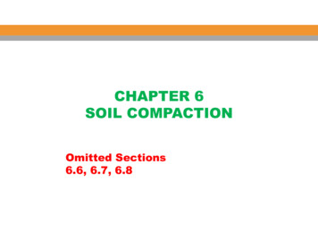
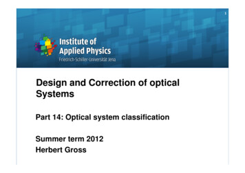
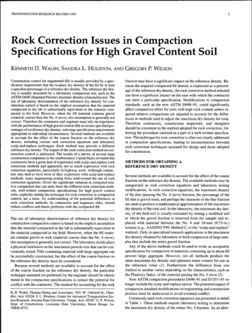
4TRANSPORTATION RESEARCH RECORD 1462TABLE 1Rock Correction T0-1AASHTOT224- Pc)D1 O. 9Pc(62.4)GmAASHT0-2AASHTOT224ASTM-1ASTM D4718DUSBR 5515-89Dr is determined using (1Method A or B, AASHTOT99 or Tl80D( determined usingMethod A or B, AASHTOT99 or T 180. ra dependson rock contentD pc62.462.4(1- Pc)GmDJpc62.462.4(1- Pc)GmruDf- USBR-1CommentsD - D[ determined usingASTM 0698 or DI 557Dr determined using USBRMethod 5500-89. rudepends on rock contentand plasticity of fines*Definitions:DfMaximum dry density of finer material (pcf)DMaximum dry density of finer soil (pcf)Percent rock by weight (decimal)Bulk specific gravity of rockCo.rrection factor in AASHTO equation to account for interference of large aggregateCorrection factor in USBR equation to account for interference of large aggregatenative to using one of the rock correction equations, small-scalecompaction tests on material containing particle sizes up to 19 mm(0.75 in.) may be used to determine a reference dry density. Themost common laboratory procedure is the scalp-and-replacemethod, sometimes referred to as the procedure for replacement ofoversized aggregate. Scalp-and-replace methods involve the removal of all material larger than 19 mm and replacement with anequal weight of No. 4 to 19-mm material. Commonly used scalpand-replace methods are ASTM procedure D698-78, Method D,and ASTM D1557-78, Method D, using a mold 15 cm (6 in.) in diameter; AASHTO T99, Method C, using a 10-cm (4-in.) mold; orAASHTO 180, using a mold 15 cm in diameter. The ASTM procedures for scalp-and-replace are no longer included in the ASTMD698-91 and D1557-91 standards, but have been used extensivelyin the recent past for compaction of fills.COMPARISON OF REFERENCE DENSITIESIn general, the effect of increasing the rock content of a given soilis to increase the maximum dry density. This occurs because thespecific gravity of the rock is usually much higher than that of thebulk material between the rock fragments. The percentage increasein maximum dry density (relative to zero rock content) as a function of percent rock is shown in Figure 1 (2--4). Several methods areavailable for determining maximum dry density of soils containinglarge aggregate.The differences among the various methods for obtaining reference dry density have been found to be most significant for clayeysoils (2). The rock correction equations presented in Table 1 wereused to estimate the maximum dry density for five medium- to highplasticity clayey soils. The maximum dry densities computed usingthe rock correction equations were compared to each other and tomaximum dry densities obtained using the scalp-and-replace procedure (ASTM D698-78, Method D). Rock contents were varied inthe laboratory from 10 to 60 percent, and the rock gradations consisted of material between the No. 4 and 19-mm sieves. When therock contents were changed in the laboratory, the gradation of theminus No. 4 material was left unchanged, and the percentage byweight of the plus No. 4 material was increased or decreased asrequired.
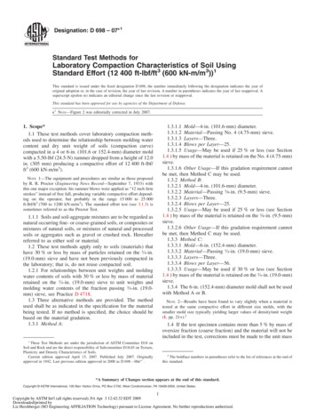
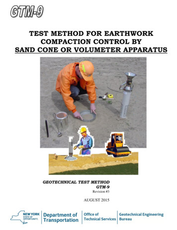
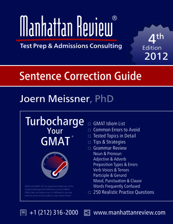
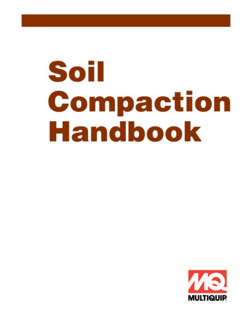
Walsh eta!.520. Houston and Walsh (1993) - Clayey Soils(Up to 19 mm rock tested)- - - Day (1991) - Clayey Soils(Up to 19 mm rock tested)15----- , !-e- Hsu and Saxena (1991) - Granular Soils(Up to 76 mm rock tested)i:1 0 1----- -----r------'---V---15S- t · ---l---l11002030405060%ROCKFIGURE 1Effect of rock on maximum dry density.In all cases the maximum dry density estimated from the rock correction equations was greater than the maximum dry density obtained from the scalp-and-replace compaction method. The percentage difference by which the rock correction equation exceeds themaximum dry density obtained from ASTM Method D increaseswith increasing rock content for equations AASHT0-1 and ASTM1, as shown in Figure 2 and Figure 3. The AASHT0-2 equation incorporates a factor that provides a correction for the increased in-terference of the coarse aggregate on the compaction of the fine fraction as rock content increases The AASHT0-2 equation estimateswere 1.5 to 3.5 percent higher than the scalp-and-replace at all rockcontents. The USBR-1 equation includes different correction factorsbased on the character of the minus No. 4 fraction. Estimates usingthe USBR-1 equation were higher than the scalp-and-replace estimates by about 3.0 to 6.5 percent at all rock contents.The scalp-and-replace dry density was selected as a convenientbasis for comparison. This selection should not be construed as anendorsement of the scalp-and-replace method over the other methods. The emphasis here is not on determining which value is the"correct" maximum density for a given fill soil containing largeaggregate. In fact, it may well be that the whole question of the "correct'' value is without meaning for such fills. The point of a compaction specification written in terms of a maximum density is toachieve a suitably dense fill, and not to achieve a given fraction ofthe maximum point on a curve developed with a testing method thatarguably bears little resemblance to the actual compaction methodin the field.Specifications are written in terms of relative compaction insteadof absolute density only because the performance of different soiltypes tends to be normalized by the maximum dry density. However, when considering the compaction of soils with large aggregate, selection of the rock correction method to establish maximumdensities will likely be based on the experience of the designer withrock correction methods and related performance. Equally goodspecifications could be written with any rock correction method, aslong as the differences between the results obtained with the differ- 7 U5zw0 a: 50 4z w(.)wa:w0 l Estimate Basedon AASHT0-13 LLLL0 62 0 4020%ROCKFIGURE 2Comparison of maximum dry density estimates using scalp-and-replace method and AASHT0-1.60
6TRANSPORTATION RESEARCH RECORD 1462Limit ofRecommended Range10 8 U5zwCl Cl6 w w4a:wu.u.cs fl2 0Estimate BasedonASTM-1204060%ROCKFIGURE 3 Comparison of maximum dry density using scalp-and-replace method andASTM equation.ent methods are understood. Therefore although arguments can bemade about which method is better, this discussion is dedicated onlyto pointing out that the methods are different.IMPLICATIONS FOR CONSTRUCTIONThe maximum dry density of a clayey soil was determined atseveral rock contents, ranging from 0 to 60 percent, using severalrock correction equations. The maximum dry density of this clayeysoil was also determined using ASTM 0698-78, Method D, scalpand-replace. The clayey soil tested exhibited moderate expansivecharacteristics, having a plasticity index of 35. A compaction specification of 95 percent of the maximum dry density was selected fordiscussion purposes. This specification was applied to the maximum dry densities computed using the different rock correctionmethods to develop the actual required density to be accomplishedin the field. The results are shown in Figure 4.The actual required field density depends significantly on therock correction method. At about 60 percent rock, for example, therequired fill densities range from about 17 .9 kN/m 3 (114 pcf) toabout 19.6 kN/m 3 (125 pcf). These differences in required fill density amount to differences in the compactive effort that would be required to meet a specification. A contractor with experience withfield control by scalp-and-replace
and ASTM D1557-78, Method D, using a mold 15 cm (6 in.) in di ameter; AASHTO T99, Method C, using a 10-cm (4-in.) mold; or AASHTO 180, using a mold 15 cm in diameter. The ASTM proce dures for scalp-and-replace are no longer included in the ASTM D698-91 and D1557-91 standards, but have been used extensively in the recent past for compaction of fills. COMPARISON OF REFERENCE DENSITIES In .