Transcription
SBI-6119P-T3NSuperBlade ModuleUser’s ManualRevison 1.0a
SBI-6119P-T3N SuperBlade Module User’s ManualThe information in this User’s Manual has been carefully reviewed and is believed to be accurate. Thevendor assumes no responsibility for any inaccuracies that may be contained in this document, andmakes no commitment to update or to keep current the information in this manual, or to notify any personor organization of the updates. Please Note: For the most up-to-date version of this manual, pleasesee our website at www.supermicro.com.Super Micro Computer, Inc. ("Supermicro") reserves the right to make changes to the product describedin this manual at any time and without notice. This product, including software and documentation, is theproperty of Supermicro and/or its licensors, and is supplied only under a license. Any use or reproductionof this product is not allowed, except as expressly permitted by the terms of said license.IN NO EVENT WILL Super Micro Computer, Inc. BE LIABLE FOR DIRECT, INDIRECT, SPECIAL,INCIDENTAL, SPECULATIVE OR CONSEQUENTIAL DAMAGES ARISING FROM THE USE ORINABILITY TO USE THIS PRODUCT OR DOCUMENTATION, EVEN IF ADVISED OF THE POSSIBILITYOF SUCH DAMAGES. IN PARTICULAR, SUPER MICRO COMPUTER, INC. SHALL NOT HAVELIABILITY FOR ANY HARDWARE, SOFTWARE, OR DATA STORED OR USED WITH THE PRODUCT,INCLUDING THE COSTS OF REPAIRING, REPLACING, INTEGRATING, INSTALLING ORRECOVERING SUCH HARDWARE, SOFTWARE, OR DATA.Any disputes arising between manufacturer and customer shall be governed by the laws of Santa ClaraCounty in the State of California, USA. The State of California, County of Santa Clara shall be theexclusive venue for the resolution of any such disputes. Supermicro's total liability for all claims will notexceed the price paid for the hardware product.exceed the price paid for the hardware product.FCC Statement: This equipment has been tested and found to comply with the limits for a Class A digitaldevice pursuant to Part 15 of the FCC Rules. These limits are designed to provide reasonable protectionagainst harmful interference when the equipment is operated in an industrial environment. Thisequipment generates, uses, and can radiate radio frequency energy and, if not installed and used inaccordance with the manufacturer’s instruction manual, may cause harmful interference with radiocommunications. Operation of this equipment in a residential area is likely to cause harmful interference,in which case you will be required to correct the interference at your own expense.California Best Management Practices Regulations for Perchlorate Materials: This Perchlorate warningapplies only to products containing CR (Manganese Dioxide) Lithium coin cells. “PerchlorateMaterial-special handling may apply. See NING: This product can expose you to chemicals includinglead, known to the State of California to cause cancer and birthdefects or other reproductive harm. For more information, goto www.P65Warnings.ca.gov.Manual Revison 1.0aRelease Date: July 2, 2020Unless you request and receive written permission from Super Micro Computer, Inc., you may not copyany part of this document. Information in this document is subject to change without notice. Otherproducts and companies referred to herein are trademarks or registered trademarks of their respectivecompanies or mark holders.Copyright 2020 by Super Micro Computer, Inc.All rights reserved.Printed in the United States of Americaii
:PrefaceAbout this ManualThis manual is written for professional system integrators, Information Technologyprofessionals, service personnel and technicians. It provides information for theinstallation and use of the Supermicro SuperBlade system’s SBI-6119P-T3NSuperBlade module. Installation and maintenance should be performed by experiencedprofessionals only.Manual OrganizationChapter 1: IntroductionThe first chapter provides a checklist of the main components included withSBI-6119P-T3N SuperBlade module and describes their main features.Chapter 2: System SafetyYou should familiarize yourself with this chapter for a general overview of safetyprecautions that should be followed when installing and servicing SBI-6119P-T3NSuperBlade module.Chapter 3: Setup and InstallationRefer to this chapter for details on installing the SBI-6119P-T3N SuperBlade module intothe SuperBlade chassis. Other sections cover the installation and placement of memorymodules and the installation of hard disk drives into the blade module.Chapter 4: Blade Module FeaturesThis chapter coves features and component information about SBI-6119P-T3NSuperBlade module. Included here are descriptions and information for mainboardcomponents, connectors, LEDs and other features of the blade module.Chapter 5: BIOSBIOS setup is covered in this chapter for SBI-6119P-T3N SuperBlade module.Appendix A: BIOS POST CodesBIOS POST Codes for SBI-6119P-T3N SuperBlade module are explained in thisappendix.iii
SBI-6119P-T3N SuperBlade Module User’s Manualiv
Table of ContentsChapter 1Introduction . 1-11-1 Overview . 1-11-2 Product Checklist of Typical Components. 1-11-3 Blade Module Features . 1-2Processors . 1-2Memory . 1-2Storage . 1-3RAID . 1-3Enclosure Requirements. 1-3Density . 1-3BMC Password . 1-41-4 Contacting Supermicro . 1-5Chapter 2Standardized Warning Statements . 2-12-1 About Standardized Warning Statements . 2-1Warning Definition. 2-1Installation Instructions . 2-3Circuit Breaker . 2-4Power Disconnection Warning . 2-5Equipment Installation. 2-6Restricted Area . 2-7Battery Handling . 2-9Redundant Power Supplies . 2-10Backplane Voltage . 2-11Comply with Local and National Electrical Codes. 2-12Product Disposal. 2-14Hot Swap Fan Warning . 2-15Power Cable and AC Adapter . 2-16Chapter 3Setup and Installation . 3-13-1 Overview . 3-13-2 Installing Blade Modules . 3-1Powering Up a Blade Unit. 3-1v
SBI-6119P-T3N SuperBlade Module User’s ManualPowering Down a Blade Unit . 3-1Removing a Blade Unit from the Enclosure . 3-2Installing a Blade Unit into the Enclosure . 3-23-3 Processor Installation . 3-4Overview of the Processor Socket Assembly . 3-5Overview of the Processor Heatsink Module (PHM). 3-6Attaching the Processor to the Narrow Processor Clip to Create theProcessor Package Assembly . 3-7Attaching the Processor Package Assembly to the Heatsink to Form theProcessor Heatsink Module (PHM). 3-8Preparing the CPU Socket for Installation . 3-10Removing the Dust Cover from the CPU Socket . 3-10Removing the Processor Heatsink Module (PHM) from the Motherboard.3-123-4 Onboard Battery Installation . 3-133-5 Memory Installation . 3-13Memory Support . 3-13Memory Population Guidelines . 3-15Memory Population Sequence. 3-16Installing Memory. 3-16ESD Precautions. 3-16Installing Memory . 3-17Removing Memory . 3-173-6 Hard Disk Drive Installation . 3-173-7 Installing the Operating System . 3-18Installing with an External USB CD-ROM Drive. 3-19Installing via PXE Boot. 3-19Installing via Virtual Media (Drive Redirection) . 3-193-8 Management Software . 3-193-9 Configuring and Setting up RAID . 3-19Chapter 4Blade Module Features. 4-14-1 Control Panel . 4-2Power Button . 4-24-2 Mainboard. 4-3CMOS Clear. 4-5Jumper Settings . 4-54-3 Blade Unit Components . 4-6vi
Table of ContentsMemory Support . 4-6Hard Disk Drives . 4-7Chapter 5BIOS . 5-15-1 Introduction. 5-1System BIOS . 5-1How To Change the Configuration Data . 5-1Starting the Setup Utility . 5-15-2 BIOS Updates . 5-25-3 Running Setup . 5-25-4 Main BIOS Setup. 5-35-5 Advanced Setup . 5-55-6 Event Logs Setup . 5-175-7 IPMI Setup . 5-195-8 Security . 5-215-9 Boot . 5-235-10 Save & Exit. 5-25vii
SBI-6119P-T3N SuperBlade Module User’s Manualviii
Chapter 1: IntroductionChapter 1Introduction1-1OverviewSATA3/NVMe user’s manual covers the SBI-6119P-T3N blade module. This blademodule is a compact self-contained server that connects into a pre-cabled enclosurethat provides power, cooling, management and networking functions. One enclosure forthe SBI-6119P-T3N blade module can hold up to 10 blade units in the 6U EnclosureSBE-610J(B)-822/622/422 model enclosures (8x2200W power supplies required for fullenclosure capacity).In this manual, “blade system” refers to the entire system (including the enclosure andblades units), “blade” or “blade unit” refers to a single blade module, “Node” refers to asingle node in each blade module and “blade enclosure” is the chassis that the blades,power supplies and modules are housed within.Please refer to our website for information on operating systems that have been certifiedfor use with the SuperBlade (www.supermicro.com/products/superblade/).Note: For your system to work properly, please follow the links below to download allnecessary drivers/utilities and the user’s manual for your server. Supermicro product manuals: http://www.supermicro.com/support/manuals/ Product drivers and utilities: ftp://ftp.supermicro.com Product safety information: ttp://www.supermicro.com/about/policies/safety information.cfm If you have any questions, please contact our support team at:support@supermicro.comNote: A complete list of safety warnings is provided on the Supermicro website athttp://www.supermicro.com/about/policies/safety information.cfm.1-2Product Checklist of Typical ComponentsYour blade module ships with its B11SPE-CPU-TF/25G mainboard already installed inits chassis. Memory, hard disk drives and the CPU must all be installed by the user aftershipment. See Chapter 3: "Setup and Installation" on page 3-1 for details on installationof these components.The blade module’s serverboard can have a mezzanine card added to your blademodule for InfiniBand, which allows you to use InfiniBand communication for your blademodule.Typical support modules for systems with the SBI-6119P-T3N blade module whenmounted in an 6U enclosure system include the following: MBM-CMM-001 or MBM-CMM-FIO CMM module (up to 2) MBM-XEM-002 10G switch modules (up to 2)1-1
SBI-6119P-T3N SuperBlade Module User’s Manual 1-3SBM-25G-100 switch modules (up to 2)Blade Module FeaturesTable 1-1 lists the main features of the SBI-6119P-T3N blade module. See theproceeding section for components typically included in a blade system and otheroptional components. Specific details for the SBI-6119P-T3N blade module are found inChapter 4: "Blade Module Features" on page 4-1.Table 1-1. SBI-6119P-T3N SuperBlade Module Specification FeaturesMainboardB11SPE-CPU-TF/25G (proprietary form factor)ProcessorsSingle Intel Xeon Scalable Socket P LGA3647 processors for each node.Please refer to our website for a complete listing of supported processors.UPI SpeedUPI up to 10.4 GT/sChipsetOne Intel C622 chip setGraphics ControllerIntegrated Aspeed AST2500 VGA Graphics chip for each nodeBIOS128 Mb SPI Flash EEPROM with AMI BIOS for each nodeMemory CapacitySupports up to 1.5 TB of RDIMM/LRDIMM DDR4 2666/2400 MHz speed and 8GB, 16 GB, 32 GB, 64 GB and 128 GB size SDRAM memory in twelve (12)288-pin DIMM sockets. See y/X11 memory config guide.pdf for details.Hard Drive BaysIncludes three hot-swap 2.5" SATA3/NVMe disk drivesAdd-on CardsThe SBI-6119P-T3N blade module can use optional add-on cards for a TPMsecurity module, Intel VROC RAID card or a Hardware RSTe key upgrademodule.System Weight10.5 lbs (4.76 kg)System Dimensions(HxWxD): 9.76 x 1.75 x 23.5” (247.9 x 44.45 x 596.9-mm)ProcessorsThe SBI-6119P-T3N SuperBlade module supports a single Intel Xeon Scalable, SocketP LGA 3647 series processor.Refer to the Supermicro website for a complete listing of supported processors (http://www.supermicro.com/products/superblade). Please note that you will need to check thedetailed specifications of a particular blade module for a list of the CPUs it supports.Details on installation of the processor into the SBI-6119P-T3N SuperBlade module arefound in Chapter 3: "Setup and Installation" on page 3-1.MemoryThe SBI-6119P-T3N SuperBlade module has twelve (12) 288-pin DIMM sockets thatcan support up to 1.5 TB of RDIMM/LRDIMM DDR4 2666/2400 MHz speed, 8 GB, 16GB, 32 GB, 64 GB and 128 GB size memory per node. Memory is interleaved, whichrequires modules of the same size and speed to be installed in groups (of two or three).1-2
Chapter 1: IntroductionPlease refer to the Supermicro website for a list of supported memory(www.supermicro.com/products/superblade). The detailed specifications for a blademodule will contain a link to a list of recommended memory sizes and manufacturers.Details on installation of memory modules into the SBI-6119P-T3N SuperBlade moduleare found in Chapter 3: "Setup and Installation" on page 3-1.StorageThe SBI-6119P-T3N SuperBlade module has three SATA3/NVMe 2.5” HDD drives infront-mounted easily removable hot-swap carriers.See Chapter 3: "Setup and Installation" on page 3-1 for storage installation details.RAIDEach SBI-6119P-T3N blade module supports several hard drives, which may create aRAID system for the blade module. For RAID setup see http://www.supermicro.com/support/manuals/ under RAID Installation Guides for more details.Enclosure RequirementsThe SBI-6119P-T3N blade module requires one of the following enclosures to run in: SBE-610J-822 SBE-610J-622 SBE-610J-422 SBE-610JB-422The SBI-6119P-T3N blade module also requires a power supply in the enclosure to runthe blade module. Available SuperBlade power supplies can be found on theSupermicro website at owersupply/.DensityA maximum of 10 SBI-6119P-T3N blade modules may be installed into a single bladeenclosure. Each blade enclosure is a 6U form factor, so a standard 42U rack mayaccommodate up to seven enclosures with 70 blade modules, or the equivalent of 70 1Uservers. With the inclusion of fourteen CMM modules and twenty-eight 1G/25G Ethernetswitches, this would occupy up to 98U space in a conventional 1U server configuration.1-3
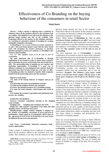
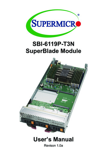
SBI-6119P-T3N SuperBlade Module User’s ManualBMC PasswordFor security, each blade unit is assigned a unique default BMC password for the ADMINuser. It can be found on a sticker on the blade service tab, and a sticker on themotherboard. The sticker also displays the BMC MAC address. For more information,refer to our website at https://www.supermicro.com/en/support/BMC Unique Password. The service tab and an example sticker are illustrated below.Service TabPasswordSticker1-4
Chapter 1: Introduction1-4Contacting SupermicroHeadquartersAddress:Supermicro Computer, Inc.980 Rock Ave.San Jose, CA 95131 U.S.A.Tel:Fax:Email:website: 1 (408) 503-8000 1 (408) 503-8008marketing@supermicro.com (General Information)support@supermicro.com (Technical Support)www.supermicro.comEuropeAddress:Supermicro Computer B.V.Het Sterrenbeeld 28, 5215 ML‘s-Hertogenbosch, The NetherlandsTel: 31 (0) 73-6400390Fax: 31 (0) 73-6416525sales@supermicro.nl (General Information)Email:support@supermicro.nl (Technical Support)rma@supermicro.nl (Customer Support)Asia-PacificAddress:Supermicro Computer, Inc.3F, No. 150, Jian 1st Rd.Zhonghe Dist., New Taipei City 23511Taiwan (R.O.C)Tel: 886-(2) 8226-3990Fax: 886-(2) 8226-3992website:www.supermicro.com.twTechnical Support:Email:support@supermicro.com.twTel: 886-(2)-8226-39901-5
SBI-6119P-T3N SuperBlade Module User’s Manual1-6
Chapter 2: Standardized Warning StatementsChapter 2Standardized Warning Statements2-1About Standardized Warning StatementsThe following statements are industry standard warnings, provided to warn the user ofsituations which have the potential for bodily injury. Should you have questions orexperience difficulty, contact Supermicro's Technical Support department forassistance. Only certified technicians should attempt to install or configure components.Read this appendix in its entirety before installing or configuring components in theSupermicro chassisThese warnings may also be found on our website at http://www.supermicro.com/about/policies/safety information.cfm.Warning DefinitionWarning!This warning symbol means danger. You are in a situation that could causebodily injury. Before you work on any equipment, be aware of the hazardsinvolved with electrical circuitry and be familiar with standard practices for ��容。2-1
SBI-6119P-T3N MicroBlade Module User’s ManualWarnungWICHTIGE SICHERHEITSHINWEISEDieses Warnsymbol bedeutet Gefahr. Sie befinden sich in einer Situation, die zuVerletzungen führen kann. Machen Sie sich vor der Arbeit mit Geräten mit denGefahren elektrischer Schaltungen und den üblichen Verfahren zur Vorbeugung vorUnfällen vertraut. Suchen Sie mit der am Ende jeder Warnung angegebenenAnweisungsnummer nach der jeweiligen Übersetzung in den übersetztenSicherheitshinweisen, die zusammen mit diesem Gerät ausgeliefert wurden.BEWAHREN SIE DIESE HINWEISE GUT AUF.INSTRUCCIONES IMPORTANTES DE SEGURIDADEste símbolo de aviso indica peligro. Existe riesgo para su integridad física. Antes demanipular cualquier equipo, considere los riesgos de la corriente eléctrica yfamiliarícese con los procedimientos estándar de prevención de accidentes. Al final decada advertencia encontrará el número que le ayudará a encontrar el texto traducido enel apartado de traducciones que acompaña a este dispositivo.GUARDE ESTAS INSTRUCCIONES.IMPORTANTES INFORMATIONS DE SÉCURITÉCe symbole d'avertissement indique un danger. Vous vous trouvez dans une situationpouvant entraîner des blessures ou des dommages corporels. Avant de travailler sur unéquipement, soyez conscient des dangers liés aux circuits électriques etfamiliarisez-vous avec les procédures couramment utilisées pour éviter les accidents.Pour prendre connaissance des traductions des avertissements figurant dans lesconsignes de sécurité traduites qui accompagnent cet appareil, référez-vous au numérode l'instruction situé à la fin de chaque avertissement.CONSERVEZ CES INFORMATIONS. תקנון הצהרות אזהרה על מנת להזהיר את המשתמש מפני חבלה , הצהרות הבאות הן אזהרות על פי תקני התעשייה יש ליצור קשר עם מחלקת תמיכה , במידה ויש שאלות או היתקלות בבעיה כלשהי . פיזית אפשרית . טכנאים מוסמכים בלבד רשאים להתקין או להגדיר את הרכיבים . טכנית של סופרמיקרו . יש לקרוא את הנספח במלואו לפני התקנת או הגדרת הרכיבים במארזי סופרמיקרו . ﺗﺤﺬﯾﺮ!ھﺬا اﻟﺮﻣﺰ ﯾﻌﻨﻲ ﺧﻄﺮ اﻧﻚ ﻓﻲ ﺣﺎﻟﺔ ﯾﻤﻜﻦ أن ﺗﺘﺴﺒﺐ ﻓﻲ اﺻﺎﺑﺔ ﺟﺴﺪﯾﺔ ﻛﻦ ﻋﻠﻰ ﻋﻠﻢ ﺑﺎﻟﻤﺨﺎطﺮ اﻟﻨﺎﺟﻤﺔ ﻋﻦ اﻟﺪواﺋﺮ ، ﻗﺒﻞ أن ﺗﻌﻤﻞ ﻋﻠﻰ أي ﻣﻌﺪات اﻟﻜﮭﺮﺑﺎﺋﯿﺔ وﻛﻦ ﻋﻠﻰ دراﯾﺔ ﺑﺎﻟﻤﻤﺎرﺳﺎت اﻟﻮﻗﺎﺋﯿﺔ ﻟﻤﻨﻊ وﻗﻮع أي ﺣﻮادث اﺳﺘﺨﺪم رﻗﻢ اﻟﺒﯿﺎن اﻟﻤﻨﺼﻮص ﻓﻲ ﻧﮭﺎﯾﺔ ﻛﻞ ﺗﺤﺬﯾﺮ ﻟﻠﻌﺜﻮر ﺗﺮﺟﻤﺘﮭﺎ 2-2
Chapter 2: Standardized Warning Statements안전을 위한 주의사항경고 !이 경고 기호는 위험이 있음을 알려 줍니다 . 작업자의 신체에 부상을 야기 할 수 있는상태에 있게 됩니다 . 모든 장비에 대한 작업을 수행하기 전에 전기회로와 관련된 위험요소들을 확인하시고 사전에 사고를 방지할 수 있도록 표준 작업절차를 준수해 주시기바랍니다 .해당 번역문을 찾기 위해 각 경고의 마지막 부분에 제공된 경고문 번호를 참조하십시오BELANGRIJKE VEILIGHEIDSINSTRUCTIESDit waarschuwings symbool betekent gevaar. U verkeert in een situatie die lichamelijkletsel kan veroorzaken. Voordat u aan enige apparatuur gaat werken, dient u zichbewust te zijn van de bij een elektrische installatie betrokken risico's en dient u op dehoogte te zijn van de standaard procedures om ongelukken te voorkomen. Gebruik denummers aan het eind van elke waarschuwing om deze te herleiden naar dedesbetreffende locatie.BEWAAR DEZE INSTRUCTIESInstallation InstructionsWarning!Read the installation instructions before connecting the system to the ��さい。警告将此系统连接电源前 , �連接前,請先閱讀安裝說明。WarnungVor dem Anschließen des Systems an die Stromquelle die Installationsanweisungenlesen.¡Advertencia!Lea las instrucciones de instalación antes de conectar el sistema a la red dealimentación.2-3
SBI-6119P-T3N MicroBlade Module User’s ManualAttentionAvant de brancher le système sur la source d'alimentation, consulter les directivesd'installation. יש לקרוא את הוראות התקנה לפני חיבור המערכת למקור מתח اﻗﺮ إرﺷﺎدات اﻟﺘﺮﻛﯿﺐ ﻗﺒﻞ ﺗﻮﺻﯿﻞ اﻟﻨﻈﺎم إﻟﻰ ﻣﺼﺪر ﻟﻠﻄﺎﻗﺔ 시스템을 전원에 연결하기 전에 설치 안내를 읽어주십시오 .WaarschuwingRaadpleeg de installatie-instructies voordat u het systeem op de voedingsbron aansluit.Circuit BreakerWarning!This product relies on the building's installation for short-circuit (overcurrent)protection. Ensure that the protective device is rated not greater than: 250 V,20 ��置の定格が 250 V、20 A �产品的短路 ( 过载电流 ) 保护由建筑物的供电系统提供 , 确保短路保护设备的额定电流不大于 250V,20A。警告此產品的短路 ( 過載電流 ) 保護由建築物的供電系統提供 , 確保短路保護設備的額定電流不大於 250V,20A。WarnungDieses Produkt ist darauf angewiesen, dass im Gebäude ein Kurzschluss- bzw.Überstromschutz installiert ist. Stellen Sie sicher, dass der Nennwert derSchutzvorrichtung nicht mehr als: 250 V, 20 A beträgt.¡Advertencia!Este equipo utiliza el sistema de protección contra cortocircuitos (o sobrecorrientes) deledificio. Asegúrese de que el dispositivo de protección no sea superior a: 250 V, 20 A.AttentionPour ce qui est de la protection contre les courts-circuits (surtension), ce produit dépendde l'installation électrique du local. Vérifiez que le courant nominal du dispositif deprotection n'est pas supérieur à :250 V, 20 A.2-4
Chapter 2: Standardized Warning Statements יש לוודא כי . מוצר זה מסתמך על הגנה המותקנת במבנים למניעת קצר חשמלי 250 V, 20 A- המכשיר המגן מפני הקצר החשמלי הוא לא יותר מ ھﺬا اﻟﻤﻨﺘﺞ ﯾﻌﺘﻤﺪ ﻋﻠﻰ ﻣﻌﺪات اﻟﺤﻤﺎﯾﺔ ﻣﻦ اﻟﺪواﺋﺮاﻟﻘﺼﯿﺮة اﻟﺘﻲ ﺗﻢ ﺗﺜﺒﯿﺘﮭﺎ ﻓﻲ اﻟﻤﺒﻨﻰ 20A, 250V : ﺗﺄﻛﺪ ﻣﻦ أن ﺗﻘﯿﯿﻢ اﻟﺠﮭﺎز اﻟﻮﻗﺎﺋﻲ ﻟﯿﺲ أﻛﺜﺮ ﻣﻦ 경고 !이 제품은 전원의 단락 ( 과전류 ) 방지에 대해서 전적으로 건물의 관련 설비에 의존합니다 . 보호장치의 정격이 반드시 250V( 볼트 ), 20A( 암페어 ) 를 초과하지 않도록 해야합니다 .WaarschuwingDit product is afhankelijk van de kortsluitbeveiliging (overspanning) van uw electrischeinstallatie. Controleer of het beveiligde aparaat niet groter gedimensioneerd is dan250V, 20A.Power Disconnection WarningWarning!The system must be disconnected from all sources of power and the powercord removed from the power supply module(s) before accessing the chassisinterior to install or remove system 移除内部器件前 , 必须将系统完全断电 , ��電,並移除電源線。WarnungDas System muss von allen Quellen der Energie und vom Netzanschlusskabel getrenntsein, das von den Spg.Versorgungsteilmodulen entfernt wird, bevor es auf denChassisinnenraum zurückgreift, um Systemsbestandteile anzubringen oder zuentfernen.2-5
SBI-6119P-T3N MicroBlade Module User’s Manual¡Advertencia!El sistema debe ser disconnected de todas las fuentes de energía y del cable eléctricoquitado de los módulos de fuente de alimentación antes de tener acceso el interior delchasis para instalar o para quitar componentes de sistema.AttentionLe système doit être débranché de toutes les sources de puissance ainsi que de soncordon d'alimentation secteur avant d'accéder à l'intérieur du chassis pour installer ouenlever des composants de systéme. אזהרה מפני ניתוק חשמלי ! אזהרה יש לנתק את המערכת מכל מקורות החשמל ויש להסיר את כבל החשמלי מהספק . לפני גישה לחלק הפנימי של המארז לצורך התקנת או הסרת רכיבים ﯾﺠﺐ ﻓﺼﻞ اﻟﻨﻈﺎم ﻣﻦ ﺟﻤﯿﻊ ﻣﺼﺎدر اﻟﻄﺎﻗﺔ وإزاﻟﺔ ﺳﻠﻚ اﻟﻜﮭﺮﺑﺎء ﻣﻦ وﺣﺪة اﻣﺪاد اﻟﻄﺎﻗﺔ ﻗﺒﻞ اﻟﻮﺻﻮل إﻟﻰ اﻟﻤﻨﺎطﻖ اﻟﺪاﺧﻠﯿﺔ ﻟﻠﮭﯿﻜﻞ ﻟﺘﺜﺒﯿﺖ أو إزاﻟﺔ ﻣﻜﻮﻧﺎت اﻟﺠﮭﺎز 경고 !시스템에 부품들을 장착하거나 제거하기 위해서는 섀시 내부에 접근하기 전에 반드시전원 공급장치로부터 연결되어있는 모든 전원과 전기코드를 분리해주어야 합니다 .WaarschuwingVoordat u toegang neemt tot het binnenwerk van de behuizing voor het installeren ofverwijderen van systeem onderdelen, dient u alle spanningsbronnen en allestroomkabels aangesloten op de voeding(en) van de behuizing te verwijderen.Equipment InstallationWarning!Only trained and qualified personnel should be allowed to install, replace, orservice this �員才可安裝、更換與維修此設備。2-6
Chapter 2: Standardized Warning StatementsWarnungDas Installieren, Ersetzen oder Bedienen dieser Ausrüstung sollte nur geschultem,qualifiziertem Personal gestattet werden.¡Advertencia!Solamente el personal calificado deb
1-1 Chapter 1: Introduction Chapter 1 Introduction 1-1 Overview SATA3/NVMe user's manual covers the SBI-6119P-T3N blade module. This blade module is a compact self-contained server that connects into a pre-cabled enclosure